EP0906862B1 - Mécanisme de direction pour véhicule automobile - Google Patents
Mécanisme de direction pour véhicule automobile Download PDFInfo
- Publication number
- EP0906862B1 EP0906862B1 EP19980118280 EP98118280A EP0906862B1 EP 0906862 B1 EP0906862 B1 EP 0906862B1 EP 19980118280 EP19980118280 EP 19980118280 EP 98118280 A EP98118280 A EP 98118280A EP 0906862 B1 EP0906862 B1 EP 0906862B1
- Authority
- EP
- European Patent Office
- Prior art keywords
- pinion
- rack
- tubular housing
- control linkage
- steering control
- Prior art date
- Legal status (The legal status is an assumption and is not a legal conclusion. Google has not performed a legal analysis and makes no representation as to the accuracy of the status listed.)
- Expired - Lifetime
Links
Images
Classifications
-
- B—PERFORMING OPERATIONS; TRANSPORTING
- B62—LAND VEHICLES FOR TRAVELLING OTHERWISE THAN ON RAILS
- B62D—MOTOR VEHICLES; TRAILERS
- B62D5/00—Power-assisted or power-driven steering
- B62D5/06—Power-assisted or power-driven steering fluid, i.e. using a pressurised fluid for most or all the force required for steering a vehicle
- B62D5/20—Power-assisted or power-driven steering fluid, i.e. using a pressurised fluid for most or all the force required for steering a vehicle specially adapted for particular type of steering gear or particular application
- B62D5/22—Power-assisted or power-driven steering fluid, i.e. using a pressurised fluid for most or all the force required for steering a vehicle specially adapted for particular type of steering gear or particular application for rack-and-pinion type
-
- B—PERFORMING OPERATIONS; TRANSPORTING
- B62—LAND VEHICLES FOR TRAVELLING OTHERWISE THAN ON RAILS
- B62D—MOTOR VEHICLES; TRAILERS
- B62D3/00—Steering gears
- B62D3/02—Steering gears mechanical
- B62D3/12—Steering gears mechanical of rack-and-pinion type
Definitions
- the invention relates generally to improvements in steering mechanism assemblies for automotive vehicles, particularly with the aim of solving problems of the mechanical design and alignment of housing elements for accommodating the various components of the steering mechanism, and particularly to a steering control linkage assembly of the kind defined in the preamble of claim 1.
- Conventional steering control linkage housings are fabricated by casting of molten aluminum or other materials.
- a valve housing comprised generally of cast iron is also used in the case of power steering.
- the fabrication of such components is attended by various problems. Complex and precise procedures are required for assembly and alignment of a cast iron valve housing with a cast aluminum steering control linkage housing, to ensure correct skew angular positioning of the components of the steering control linkage.
- the alignment procedures may require different skew angular alignments depending on the particular variant of the steering system used, and necessitate the use of different casting molds for fabricating the elements of the steering control linkage housings and for adapting the power-assisted steering valve housing. For each situation, a specific skew angular alignment of the steering column shaft (pinion shaft) and the rack housing is required, in order for the steering system to function properly.
- This noise problem may be due to incorrect alignment of the contoured openings in the housing, but the main cause of steering system noise is axial stresses in the joints between the housing and the chassis, which stresses give rise to a force component perpendicular to the rack bar and tending to distance the rack bar from the pinion, thereby acting counter to the means integrated in the steering assembly which are intended to regulate the relative positions of the rack and pinion.
- the said axial stresses also act axially on the rack, which rack is generally mounted with releasable support means on an end bearing in the steering control linkage housing, wherewith in addition to the component of said stresses which act perpendicularly to the rack, the axial stresses give rise to an undesirable axial movement of the rack which interferes with correct interengagement of the rack and the pinion, again tending to cause the respective dentations to separate, wherewith when, in alleviation of this separation, the rack tends to return to its initial position.
- the result is noise, in an intensity and frequency which depend exclusively on the intensity of the abovementioned axial stresses.
- the conventional means used by automobile manufacturers to address these drawbacks in steering control linkages is to use high precision molds for fabricating the housings, in order to achieve the correct alignment of the steering control linkage components.
- the concept is that substantial improvement in operation will result from improvements in such alignment.
- the known technique of providing devices which periodically regulate the position of the rack bar has been used.
- the general such device comprises a manually adjustable thrust bearing which is elastically urged counter to the direction of the axial stresses. These devices function well, but when over-adjusted (which is always a possibility) the result is that the rack bar is not properly re-engaged, which is detrimental to the mechanism because the re-engagement force is too great or too small, either momentarily (dynamically) or on a sustained basis.
- US-A-3 788 159 discloses a rack and pinion steering assembly wherein a flat blade spring is used to radially preload the pinion against the rack.
- the object of the present invention is to provide an improved steering control linkage of the aforementioned type, capable of solving the problems mentioned in the foregoing. According to the invention this object is achieved by a steering control linkage assembly as defined in Claim 1.
- means are provided for automatically and accurately positioning the pinion in proper engagement with the rack, in response to displacement of the rack due to components of the abovementioned axial stresses.
- These automatic positioning means are disposed in the housing element in which the pinion is housed, and comprise an elastic organ (e.g. spring, elastic annular piece, or elastic cylindrical piece) which urges the pinion component of the steering control linkage (which pinion may be conical or cylindrical) into proper engagement with the rack when the rack becomes separated from the pinion due to stress components generated by the abovementioned axial stresses.
- an elastic organ e.g. spring, elastic annular piece, or elastic cylindrical piece
- said means are mounted in the immediate neighborhood of, and in cooperation with, a conical pinion disposed at the end of the steering column shaft.
- the dentation of said pinion corresponds to that of the rack, and does not per se provide any type of exaggerated pre-stressing against the rack.
- the rack receives additional support within the proposed housing element by mounting therein of a second guide bearing (pillow bearing) which keeps the rack aligned in said housing element in order to counter the generation of undesirable movement by the action of the abovementioned axial stresses.
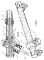
- the housing 1 is a steering control linkage housing similar to known steering control linkage housings in that it is intended as a housing to accommodate various steering control linkage components including a rack 2 and a pinion 3.
- the pinion 3 is mounted on the steering column shaft c .
- the rack is supported by way of a pillow bearing (bushing bearing) 2' disposed at the distal end of the rack.
- the housing 1 is comprised of two tubular elements (1', 1'') shown in more detail in Figs. 2 and 3.
- elements (1', 1'') both comprise steel tubes; but alternatively the element 1' which serves as a housing element for the rack 2 may comprise a steel tube, and the element 1'' which serves as a housing element for the pinion 3 may comprise a cast iron tube.
- the tubular elements 1' and 1'' of which the housing 1 is comprised are each easily machinable over their entire lengths. This feature allows precision machining to produce shoulders, seats, and like structures in their interiors, to facilitate the mounting of the rack 2 and pinion 3, and to facilitate the application of clamps, brackets, and other mounting hardware (4) for mounting the steering control linkage housing to the vehicle chassis.
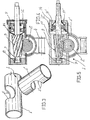
- the two tubes (1', 1'') are joined together with the aid of contoured openings (5, 5') cut into the respective tube walls (1', 1'').
- the perimeters of these openings are complementary such that appropriate support is provided when the tubes (1', 1'') are assembled together in a superposed crossed configuration the parameters of which are determined by the prescribed skew angular alignment of the steering control linkage components which results in the desired engagement of the rack 2 and pinion 3.
- the contoured opening 5' in element 1'' is smaller than the contoured opening 5 in element 1', whereby when the tubes are arranged in the desired superposed position the border region around the opening 5' provides a support for the element 1'' (Fig. 4) which facilitates the establishment of the relative angular position of the elements (1', 1'') and subsequent welding or brazing.
- This manner of joining the two elements (1', 1'') allows variations in the angular relations depending on the needs of various steering mechanisms, and avoids the difficulties in alignment when pre-cast elements are used.
- steering control linkage housings as described above can be produced for a somewhat wide range of vehicles, from the same stock pieces and with the same tooling (instead of a whole series of different casting molds).
- tubular element 1'' is comprised of cast iron, one may readily incorporate in it a structure 6 for mounting a valve complex, which structure 6 will have the proper configuration for good operation.
- a housing 1 thus constructed enables proper alignment of the rack bar 2 and the pinion 3, along with means of automatically positioning said rack bar 2 and pinion 3 in response to axial stresses exerted on said housing 1.
- a first embodiment of the described positioning means is illustrated in Figs. 1 and 3.
- the dentation of the conical pinion 3 corresponds to that of the rack 2.
- the pinion 3 is accommodated in the tubular element 1'' of the housing 1.
- the pinion shaft 7 is coaxially connected to the steering column (c) and is rotationally supported and is movable to a slight degree in the axial direction, on one side by the intermediary of a bearing 8 which closes off the end of the tubular element 1'', and on the other side by an antifriction bearing 9 mounted in the opposite end region of tubular element 1'', which end region is closed off by retainer means and a conventional end cap, collectively designated with reference numeral 10.
- the support means for the conical pinion 3 incorporates an elastic organ 11 in the form of a plate spring or elastic annular piece, which organ 11 exerts a continuous pre-stress on the conical pinion 3 in the axial direction.
- elastic organ 11 is mounted between:
- the frictional engagement characteristics of the dentations is determined by the pre-stressing of the pinion 3 by the elastic organ 11, as a consequence of the conicity of the pinion 3.
- excess engagement force between the rack 2 and pinion 3 is avoided, in that the resultant force component derived from the axial stresses, in the rack 2, is compensated.
- a final element of an assembly which annuls possible stresses on the rack 2 is provided by a second pillow bearing 13 which supports the rack in the neighborhood of the junction of the two tubular elements (1', 1''); this along with the conicity of the pinion 3 contributes to the proper functioning of the steering mechanism.
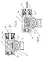
- Fig. 5 shows a variant of the embodiment of the inventive automatic pinion-positioning means shown in Fig. 4, wherein a generally annular spring 11' acts directly on an end-disposed antifriction bearing 9' which is mounted on the shaft 7 of the conical pinion 3.
- a retaining ring 12' mounted in a threaded plug piece 14 threadedly engaged in the interior of the tubular element 1'', which plug piece 14 also surrounds the elastic organ 11'.
- the described arrangements enable undesirable movements of the rack 2 to be resisted, thereby eliminating undesirable noise in the steering mechanism.
- the means of automatically positioning the components of the steering control linkage assembly incorporated in the described housing 1 are comprised of quasi-cylindrical pieces of elastic material (15, 15') having eccentric openings, for supporting the shaft 7a of a cylindrical pinion 3a which engages a rack 2.
- the elastic piece 15 is disposed at the end region of shaft 7a which end region corresponds to the blind end of the tubular element 1'; the elastic piece 15' is disposed around the antifriction bearing 9a, wherewith the end of tubular element 1'' which is opposite from the end which bears the first elastic piece 15 is closed off by a retaining ring and a conventional plug piece as in the preceding embodiment.
- the described embodiments allow one to dispense with the conventional devices for regulating the engagement of the components of the steering control linkage, and to dispense with all of the appurtenances to said regulating devices. Not only are costs reduced, but more importantly the undesirable noises are eliminated.
Landscapes
- Engineering & Computer Science (AREA)
- Chemical & Material Sciences (AREA)
- Combustion & Propulsion (AREA)
- Transportation (AREA)
- Mechanical Engineering (AREA)
- Transmission Devices (AREA)
Claims (8)
- Ensemble de tringlerie de direction manuelle ou servo-assistée pour véhicules automobiles, comprenant un carter (1) présentant des moyens de montage articulés (4) au niveau de ses extrémités destinés à fixer le carter (1) au châssis du véhicule, le carter (1) étant influencé par des contraintes axiales, avec un composant complexe dudit carter (1) étant formé à partir de deux éléments tubulaires de carter (1', 1''), disposés à un angle l'un de l'autre, un (1') des deux éléments tubulaires de carter (1', 1'') s'étendant transversalement au châssis du véhicule, et le composant de carter complexe logeant des composants de système de direction coopérant avec un arbre de colonne de direction (c) par un agencement de crémaillère et de pignon (2, 3), ledit agencement de crémaillère et de pignon (2, 3) comprenant :caractérisé en ce que des moyens de positionnement (11) sont proposés pour positionner automatiquement le pignon (3) en mise en prise avec la crémaillère (2) en réponse aux fluctuations dans la mise en prise du pignon (3) et de la crémaillère (2) afin d'éliminer le bruit indésirable dans le mécanisme de direction, lesdits moyens de positionnement (11) comprenant un organe élastique (11) monté de manière coaxiale autour d'un arbre de pignon (7) de manière à pousser continuellement le pignon (3) dans la direction axiale en mise en prise avec la crémaillère (2) et à permettre un léger déplacement axial dudit arbre (7).une barre de crémaillère (2) reliée aux roues d'un véhicule par l'intermédiaire de connexions articulées, la barre de crémaillère (2) étant supportée et guidée dans un mouvement coulissant par un palier à coussin placé à l'extrémité (2') disposée dans un intérieur d'un élément tubulaire de carter (1') orienté transversalement au châssis du véhicule, etun pignon (3) monté dans l'autre (1'') des deux éléments tubulaires de carter (1', 1''), le pignon (3) coordonnant avec l'arbre de colonne de direction (c) et mettant en prise la crémaillère (2), ledit pignon (3) étant supporté de manière rotative par une paire de paliers (8, 9) au niveau des extrémités respectives dudit autre élément tubulaire de carter (1''),les deux éléments tubulaires de carter (1', 1'') comprenant des tubes métalliques respectifs de différentes longueurs, des paliers et des supports (2', 13, 8, 9) pour la barre de crémaillère (2) et le pignon (3) étant installé dans les deux éléments tubulaires de carter (1', 1''), les deux éléments tubulaires de carter (1', 1'') étant joints dans un agencement superposé par un cordon de matériau de soudage ou de brasage disposé au niveau des bords des ouvertures respectives (5, 5') dans les parois desdits éléments tubulaires de carter (1', 1''), les ouvertures (5, 5') étant de différentes dimensions et de formes différentes correspondantes afin de former une jonction angulaire desdits deux éléments tubulaires de carter (1', 1'') dans une orientation superposée correspondant à un alignement angulaire souhaité de la tringlerie de direction, et afin de proposer un espace de communication entre lesdits deux éléments tubulaires de carter (1', 1'') pour loger la mise en prise du pignon (3) avec la crémaillère (2) quand la crémaillère (2) est logée dans le plus long (1') desdits deux éléments tubulaires de carter (1', 1'') et le pignon (3) étant logé dans le plus court (1'') desdits deux éléments tubulaires de carter (1', 1'') et ledit élément tubulaire plus long de carter (1') présentant, au niveau d'un emplacement intermédiaire dans ledit élément tubulaire plus long de carter et proche des ouvertures superposées (5, 5'), un second palier à coussin intérieur (13) pour un support coulissant de la barre de crémaillère (2) ;
- Ensemble de tringlerie de direction selon la revendication 1, dans lequel ledit pignon (3) est conique et ledit organe élastique (11) est composé d'un ressort à lames de forme annulaire disposé de manière coaxiale autour de l'arbre de pignon (7) du pignon conique (3) entre une base du pignon (3) et un palier-support (9) pour l'arbre de pignon (7).
- Ensemble de tringlerie de direction selon la revendication 1, dans lequel ledit pignon (3) est conique et ledit organe élastique (11) est composé d'un ressort à lames de forme annulaire disposé de manière coaxiale avec l'arbre de pignon (7) du pignon conique (3) entre un palier (9') installé sur ledit arbre de pignon (7) et une base d'une pièce formant bouchon (14) entourant ledit palier (9'), la pièce formant bouchon (14) étant fixée au moyen de vis à une extrémité de l'élément tubulaire plus court de carter (1'') situé en face d'une extrémité où le palier-support à billes (8) de l'arbre de pignon (7) est disposé.
- Ensemble de tringlerie de direction selon l'une quelconque des revendications précédentes, dans lequel lesdits moyens de positionnement comprennent également une paire d'organes formés de manière cylindrique (15, 15') composés de matériau élastique, disposés radialement vers l'extérieur de et de manière concentrique avec un roulement à billes (8a) et le palier-support (9a) du pignon (3a) monté à l'intérieur de l'élément tubulaire plus court du carter (1''), lesdits organes profilés (15, 15') présentant des ouvertures intérieures disposées de manière excentrique par rapport à un axe géométrique desdits organes profilés (15, 15') afin de pousser sélectivement l'arbre de pignon (7a) vers la crémaillère (2).
- Ensemble de tringlerie de direction selon la revendication 1, dans lequel lesdits moyens de positionnement comprennent également une paire d'organes formés généralement de manière cylindrique (15, 15') composés de matériau élastique, disposés radialement vers l'extérieur de et de manière généralement concentrique avec un palier-support à billes (8a) de l'arbre (7) d'un pignon cylindrique (3a) et un palier-support (9a) dudit arbre de pignon (7a) monté dans un intérieur d'une pièce formant bouchon (14), la pièce formant bouchon (14) étant fixée au moyen de vis à l'extrémité de l'élément tubulaire plus court de carter (1'') en face de l'extrémité où ledit palier-support à billes (8a) de l'arbre de pignon (7a) est disposé, et ledit organe élastique (11'), composé d'un ressort élastique à lames de forme annulaire (11') poussant le palier (9a) monté de manière co-axiale sur l'arbre de pignon (7a), est proposé entre la base de la pièce formant bouchon (14) et ledit palier (9a) fixé à l'arbre de pignon (7a).
- Ensemble de tringlerie de direction selon l'une quelconque des revendications précédentes, dans lequel lesdits deux éléments tubulaires de carter (1', 1'') sont composés d'acier et peuvent être usinés sur la totalité de leurs longueurs.
- Ensemble de tringlerie de direction selon l'une quelconque des revendications précédentes, dans lequel l'ouverture (5) dans l'élément tubulaire de carter (1') logeant la crémaillère (2) est de plus grandes dimensions que l'ouverture (5') dans le logement tubulaire de carter (1'') logeant le pignon (3), de telle manière qu'un bord de l'ouverture de l'élément de carter de crémaillère (5) supporte une région frontalière de l'ouverture de l'élément de carter de pignon (5') afin qu'une zone d'application du cordon de matériau de soudage ou de brasage soit proposée.
- Ensemble de tringlerie de direction selon l'une quelconque des revendications précédentes, dans lequel lesdits deux éléments tubulaires de carter (1', 1'') présentent également des moyens formant carter (6) pour adapter et monter un système de robinet de réglage pour une direction servo-assistée.
Applications Claiming Priority (4)
| Application Number | Priority Date | Filing Date | Title |
|---|---|---|---|
| AR10456697 | 1997-10-03 | ||
| AR9704566 | 1997-10-03 | ||
| US95943 | 1998-06-12 | ||
| US09/095,943 US6283244B1 (en) | 1997-10-03 | 1998-06-12 | Steering mechanism assembly for automotive vehicle |
Publications (3)
| Publication Number | Publication Date |
|---|---|
| EP0906862A2 EP0906862A2 (fr) | 1999-04-07 |
| EP0906862A3 EP0906862A3 (fr) | 2000-08-30 |
| EP0906862B1 true EP0906862B1 (fr) | 2003-12-10 |
Family
ID=25590815
Family Applications (1)
| Application Number | Title | Priority Date | Filing Date |
|---|---|---|---|
| EP19980118280 Expired - Lifetime EP0906862B1 (fr) | 1997-10-03 | 1998-09-26 | Mécanisme de direction pour véhicule automobile |
Country Status (2)
| Country | Link |
|---|---|
| EP (1) | EP0906862B1 (fr) |
| DE (1) | DE69820371T2 (fr) |
Families Citing this family (8)
| Publication number | Priority date | Publication date | Assignee | Title |
|---|---|---|---|---|
| FR2798896B1 (fr) * | 1999-09-24 | 2002-02-15 | Renault | Carter pour mecanisme de direction a pignon et cremaillere |
| FR2805236B1 (fr) * | 2000-02-22 | 2002-06-07 | Soc Mecanique Irigny | Dispositif de guidage de cremaillere pour mecanisme de direction de vehicule automobile |
| DE1129925T1 (de) * | 2000-02-29 | 2002-02-07 | Visteon Automotive Systems Inc., Dearborn | Verbesserungen an Lenksystemen von Kraftfahrzeugen |
| US6722465B2 (en) * | 2001-07-06 | 2004-04-20 | Visteon Global Technologies, Inc | Steering mechanism for an automotive vehicle |
| DE102014008961B4 (de) * | 2014-06-23 | 2016-12-15 | Thyssenkrupp Presta Ag | Lenkgetriebe mit deachsierter Zahnstange |
| KR102246689B1 (ko) * | 2015-01-30 | 2021-04-30 | 주식회사 만도 | 자동차의 랙 피니언 방식 조향장치 |
| CN108313122B (zh) * | 2017-01-16 | 2023-05-09 | 浙江师范大学 | 一种用于循环球液压转向器支撑调整塞摇臂轴式输出结构 |
| DE102020208275A1 (de) | 2020-07-02 | 2022-01-05 | Robert Bosch Gesellschaft mit beschränkter Haftung | Modulare elektrische Hilfskraftlenkung |
Family Cites Families (6)
| Publication number | Priority date | Publication date | Assignee | Title |
|---|---|---|---|---|
| DE1073879B (de) * | 1957-04-03 | 1960-01-21 | Auto Union G.m.b.H., Ingolstadt/ Donau | Zahnstangenlenkvorrichtung, insbesondere für Kraftfahrzeuge |
| GB1248016A (en) * | 1969-09-25 | 1971-09-29 | Burman & Sons Ltd | Steering gear |
| US3788159A (en) * | 1972-10-30 | 1974-01-29 | Gen Motors Corp | Rack and pinion steering gear |
| US4016774A (en) * | 1975-12-19 | 1977-04-12 | The Bendix Corporation | Rack and pinion steering gear |
| DE2962985D1 (en) * | 1978-05-08 | 1982-07-22 | Cam Gears Ltd | Rack and pinion gears, housings therefor and a method of manufacturing such housings |
| DE4334491A1 (de) * | 1993-10-09 | 1995-04-13 | Zahnradfabrik Friedrichshafen | Zahnstangenlenkung, insbesondere für Kraftfahrzeuge |
-
1998
- 1998-09-26 DE DE69820371T patent/DE69820371T2/de not_active Expired - Fee Related
- 1998-09-26 EP EP19980118280 patent/EP0906862B1/fr not_active Expired - Lifetime
Also Published As
| Publication number | Publication date |
|---|---|
| EP0906862A2 (fr) | 1999-04-07 |
| EP0906862A3 (fr) | 2000-08-30 |
| DE69820371D1 (de) | 2004-01-22 |
| DE69820371T2 (de) | 2004-11-11 |
Similar Documents
| Publication | Publication Date | Title |
|---|---|---|
| EP1693279B1 (fr) | Colonne de direction à commande de positionnement motorisé | |
| US5152358A (en) | Vehicle steering apparatus | |
| US7025380B2 (en) | Power telescopic type steering column | |
| US5642918A (en) | Moveable headrest | |
| US20200039567A1 (en) | Steering device | |
| US20090031844A1 (en) | Tilt-type steering apparatus | |
| US20140174843A1 (en) | Power steering device and backlash adjuster | |
| US7325833B2 (en) | Steering device for motor vehicle | |
| EP0906862B1 (fr) | Mécanisme de direction pour véhicule automobile | |
| US4240305A (en) | Retaining clamp for an adjustable steering column | |
| US6283244B1 (en) | Steering mechanism assembly for automotive vehicle | |
| US20060048597A1 (en) | Support casing for housing a steering shaft | |
| GB2297607A (en) | Clamp arrangement for an adjustable steering column | |
| CN113442996A (zh) | 转向装置 | |
| US6237954B1 (en) | Apparatus for supporting a steering column | |
| US9150239B2 (en) | Steering apparatus for a vehicle | |
| US5943916A (en) | Steering column assembly unit | |
| US5393028A (en) | Power-operated seat device for vehicle | |
| US7051612B2 (en) | Steering column assembly for a vehicle | |
| US7500414B2 (en) | Steering column device for vehicle | |
| US20050242561A1 (en) | Steering column device | |
| JP2002302046A (ja) | ステアリング装置 | |
| KR20050056295A (ko) | 조향칼럼의 틸트 및 텔레스코프 잠금 장치 | |
| JP4085802B2 (ja) | 電動式パワーステアリング装置 | |
| EP1195313B1 (fr) | Systéme de direction inclinable |
Legal Events
| Date | Code | Title | Description |
|---|---|---|---|
| PUAI | Public reference made under article 153(3) epc to a published international application that has entered the european phase |
Free format text: ORIGINAL CODE: 0009012 |
|
| AK | Designated contracting states |
Kind code of ref document: A2 Designated state(s): DE FR GB |
|
| AX | Request for extension of the european patent |
Free format text: AL;LT;LV;MK;RO;SI |
|
| RAP1 | Party data changed (applicant data changed or rights of an application transferred) |
Owner name: VISTEON AUTOMOTIVE SYSTEMS INC. |
|
| PUAL | Search report despatched |
Free format text: ORIGINAL CODE: 0009013 |
|
| AK | Designated contracting states |
Kind code of ref document: A3 Designated state(s): AT BE CH CY DE DK ES FI FR GB GR IE IT LI LU MC NL PT SE |
|
| AX | Request for extension of the european patent |
Free format text: AL;LT;LV;MK;RO;SI |
|
| 17P | Request for examination filed |
Effective date: 20010205 |
|
| AKX | Designation fees paid |
Free format text: DE FR GB |
|
| 17Q | First examination report despatched |
Effective date: 20020826 |
|
| GRAH | Despatch of communication of intention to grant a patent |
Free format text: ORIGINAL CODE: EPIDOS IGRA |
|
| GRAS | Grant fee paid |
Free format text: ORIGINAL CODE: EPIDOSNIGR3 |
|
| GRAA | (expected) grant |
Free format text: ORIGINAL CODE: 0009210 |
|
| RAP1 | Party data changed (applicant data changed or rights of an application transferred) |
Owner name: VISTEON GLOBAL TECHNOLOGIES INC. |
|
| AK | Designated contracting states |
Kind code of ref document: B1 Designated state(s): DE FR GB |
|
| PG25 | Lapsed in a contracting state [announced via postgrant information from national office to epo] |
Ref country code: FR Free format text: LAPSE BECAUSE OF FAILURE TO SUBMIT A TRANSLATION OF THE DESCRIPTION OR TO PAY THE FEE WITHIN THE PRESCRIBED TIME-LIMIT Effective date: 20031210 |
|
| REG | Reference to a national code |
Ref country code: GB Ref legal event code: FG4D |
|
| REF | Corresponds to: |
Ref document number: 69820371 Country of ref document: DE Date of ref document: 20040122 Kind code of ref document: P |
|
| PG25 | Lapsed in a contracting state [announced via postgrant information from national office to epo] |
Ref country code: GB Free format text: LAPSE BECAUSE OF NON-PAYMENT OF DUE FEES Effective date: 20040926 |
|
| PLBE | No opposition filed within time limit |
Free format text: ORIGINAL CODE: 0009261 |
|
| 26N | No opposition filed |
Effective date: 20040913 |
|
| EN | Fr: translation not filed | ||
| GBPC | Gb: european patent ceased through non-payment of renewal fee |
Effective date: 20040926 |
|
| PGFP | Annual fee paid to national office [announced via postgrant information from national office to epo] |
Ref country code: DE Payment date: 20050912 Year of fee payment: 8 |
|
| PG25 | Lapsed in a contracting state [announced via postgrant information from national office to epo] |
Ref country code: DE Free format text: LAPSE BECAUSE OF NON-PAYMENT OF DUE FEES Effective date: 20070403 |