EP0906860B1 - Articulated coupling - Google Patents
Articulated coupling Download PDFInfo
- Publication number
- EP0906860B1 EP0906860B1 EP98402422A EP98402422A EP0906860B1 EP 0906860 B1 EP0906860 B1 EP 0906860B1 EP 98402422 A EP98402422 A EP 98402422A EP 98402422 A EP98402422 A EP 98402422A EP 0906860 B1 EP0906860 B1 EP 0906860B1
- Authority
- EP
- European Patent Office
- Prior art keywords
- swivel coupling
- vehicles
- ball
- coupling according
- underframe
- Prior art date
- Legal status (The legal status is an assumption and is not a legal conclusion. Google has not performed a legal analysis and makes no representation as to the accuracy of the status listed.)
- Expired - Lifetime
Links
- 230000008878 coupling Effects 0.000 title claims description 38
- 238000010168 coupling process Methods 0.000 title claims description 38
- 238000005859 coupling reaction Methods 0.000 title claims description 38
- 230000000284 resting effect Effects 0.000 claims description 4
- 238000013016 damping Methods 0.000 description 4
- 210000004417 patella Anatomy 0.000 description 2
- 230000000452 restraining effect Effects 0.000 description 2
- 238000005096 rolling process Methods 0.000 description 2
- 229910000838 Al alloy Inorganic materials 0.000 description 1
- 229910000831 Steel Inorganic materials 0.000 description 1
- RTAQQCXQSZGOHL-UHFFFAOYSA-N Titanium Chemical compound [Ti] RTAQQCXQSZGOHL-UHFFFAOYSA-N 0.000 description 1
- 238000010521 absorption reaction Methods 0.000 description 1
- 239000000956 alloy Substances 0.000 description 1
- 229910045601 alloy Inorganic materials 0.000 description 1
- 239000002131 composite material Substances 0.000 description 1
- 230000007547 defect Effects 0.000 description 1
- 229910052751 metal Inorganic materials 0.000 description 1
- 239000002184 metal Substances 0.000 description 1
- 238000003032 molecular docking Methods 0.000 description 1
- 230000000750 progressive effect Effects 0.000 description 1
- 230000001681 protective effect Effects 0.000 description 1
- 239000010959 steel Substances 0.000 description 1
- 239000010936 titanium Substances 0.000 description 1
- 229910052719 titanium Inorganic materials 0.000 description 1
Images

Classifications
-
- B—PERFORMING OPERATIONS; TRANSPORTING
- B61—RAILWAYS
- B61G—COUPLINGS; DRAUGHT AND BUFFING APPLIANCES
- B61G1/00—Couplings comprising interengaging parts of different shape or form and having links, bars, pins, shackles, or hooks as coupling means
-
- B—PERFORMING OPERATIONS; TRANSPORTING
- B61—RAILWAYS
- B61F—RAIL VEHICLE SUSPENSIONS, e.g. UNDERFRAMES, BOGIES OR ARRANGEMENTS OF WHEEL AXLES; RAIL VEHICLES FOR USE ON TRACKS OF DIFFERENT WIDTH; PREVENTING DERAILING OF RAIL VEHICLES; WHEEL GUARDS, OBSTRUCTION REMOVERS OR THE LIKE FOR RAIL VEHICLES
- B61F5/00—Constructional details of bogies; Connections between bogies and vehicle underframes; Arrangements or devices for adjusting or allowing self-adjustment of wheel axles or bogies when rounding curves
- B61F5/02—Arrangements permitting limited transverse relative movements between vehicle underframe or bolster and bogie; Connections between underframes and bogies
- B61F5/16—Centre bearings or other swivel connections between underframes and bolsters or bogies
- B61F5/20—Centre bearings or other swivel connections between underframes and bolsters or bogies with springs allowing transverse movements
-
- B—PERFORMING OPERATIONS; TRANSPORTING
- B61—RAILWAYS
- B61F—RAIL VEHICLE SUSPENSIONS, e.g. UNDERFRAMES, BOGIES OR ARRANGEMENTS OF WHEEL AXLES; RAIL VEHICLES FOR USE ON TRACKS OF DIFFERENT WIDTH; PREVENTING DERAILING OF RAIL VEHICLES; WHEEL GUARDS, OBSTRUCTION REMOVERS OR THE LIKE FOR RAIL VEHICLES
- B61F3/00—Types of bogies
- B61F3/12—Types of bogies specially modified for carrying adjacent vehicle bodies of articulated trains
-
- B—PERFORMING OPERATIONS; TRANSPORTING
- B61—RAILWAYS
- B61G—COUPLINGS; DRAUGHT AND BUFFING APPLIANCES
- B61G5/00—Couplings for special purposes not otherwise provided for
- B61G5/02—Couplings for special purposes not otherwise provided for for coupling articulated trains, locomotives and tenders or the bogies of a vehicle; Coupling by means of a single coupling bar; Couplings preventing or limiting relative lateral movement of vehicles
-
- Y—GENERAL TAGGING OF NEW TECHNOLOGICAL DEVELOPMENTS; GENERAL TAGGING OF CROSS-SECTIONAL TECHNOLOGIES SPANNING OVER SEVERAL SECTIONS OF THE IPC; TECHNICAL SUBJECTS COVERED BY FORMER USPC CROSS-REFERENCE ART COLLECTIONS [XRACs] AND DIGESTS
- Y10—TECHNICAL SUBJECTS COVERED BY FORMER USPC
- Y10T—TECHNICAL SUBJECTS COVERED BY FORMER US CLASSIFICATION
- Y10T403/00—Joints and connections
- Y10T403/32—Articulated members
- Y10T403/32114—Articulated members including static joint
- Y10T403/32213—Articulate joint is a swivel
-
- Y—GENERAL TAGGING OF NEW TECHNOLOGICAL DEVELOPMENTS; GENERAL TAGGING OF CROSS-SECTIONAL TECHNOLOGIES SPANNING OVER SEVERAL SECTIONS OF THE IPC; TECHNICAL SUBJECTS COVERED BY FORMER USPC CROSS-REFERENCE ART COLLECTIONS [XRACs] AND DIGESTS
- Y10—TECHNICAL SUBJECTS COVERED BY FORMER USPC
- Y10T—TECHNICAL SUBJECTS COVERED BY FORMER US CLASSIFICATION
- Y10T403/00—Joints and connections
- Y10T403/32—Articulated members
- Y10T403/32606—Pivoted
- Y10T403/32614—Pivoted including circumferential biasing or damping means
-
- Y—GENERAL TAGGING OF NEW TECHNOLOGICAL DEVELOPMENTS; GENERAL TAGGING OF CROSS-SECTIONAL TECHNOLOGIES SPANNING OVER SEVERAL SECTIONS OF THE IPC; TECHNICAL SUBJECTS COVERED BY FORMER USPC CROSS-REFERENCE ART COLLECTIONS [XRACs] AND DIGESTS
- Y10—TECHNICAL SUBJECTS COVERED BY FORMER USPC
- Y10T—TECHNICAL SUBJECTS COVERED BY FORMER US CLASSIFICATION
- Y10T403/00—Joints and connections
- Y10T403/45—Flexibly connected rigid members
- Y10T403/455—Elastomer interposed between radially spaced members
- Y10T403/458—Composite bushing with elastomeric component
Definitions
- the present invention relates to connection between vehicles, in particular rail, constituting an articulated oar, in general, and carries, more particularly on a coupling joint between two vehicles, notably rail vehicles.
- Document DE-AS-1 040 063 discloses a joint coupling between two vehicles with a function of rotation and a damping function, each function of rotation and coupling being achieved by elements distinct.
- a joint presents the disadvantage of not allowing angular deflections around the longitudinal axis and is therefore not suitable for tilting vehicle.
- a toric joint element ensures the joint between a soleplate and the O-ring.
- This toric joint element is a structure composed of successive and multiple layers of metal and rubber which may be of different stiffnesses and progressive.
- a major drawback of the joint coupling of two railway vehicles described in this prior art document is that it only allows low angular deflections.
- the coupling joint of two vehicles railway described in this document of the prior art has as a disadvantage of being rigid and therefore of imposing a twisting of tilting vehicle bodies during passage of curved tracks.
- an object of the invention is a joint coupling of two vehicles, especially rail vehicles, supporting the deflection around the longitudinal axis without produce a restraining force in order to avoid any twists checkout.
- An advantage of the coupling joint of two rail vehicles the invention is to be extra-flat due to its small size.
- Another advantage of the coupling joint of two railway vehicles of the invention is that it can be integrated on pendulum articulated rolling stock or not pendulum.
- Another advantage of the coupling joint of two rail vehicles the invention is to allow to lower the level of the traffic floor by one value of the order of 200 mm.
- the coupling joint between two vehicles A, B, especially rail, resting on a middle bogie (not shown) between the two vehicles and presenting a rotation function and a damping function is such that each rotation and damping function is made by separate elements.
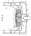
- the joint coupling comprises a central toric part 3, having a frustoconical bearing surface 3A, a ball joint 1, 2 having a hollow central conical part 1A nesting on the frustoconical bearing surface 3A of the central O-ring 3, elastic elements 4, a disc 5 and a retaining screw 6 comprising a pivot vertical 6A.
- the central toric part 3 partly comprises the tapered support surface 3A and is connected by its lower part to the chassis 9 of the body of one vehicles B.
- the ball 1, 2 combines a first element 1 of shape general spherical to a second external element 2 arranged free to rotate on the first element 1.
- the elastic elements 4 are, preferably at number of two, generally semicircular and are symmetrically arranged on either side of the ball 1, 2 and the longitudinal axis of the vehicle so as to take support against the external surface of the second element 2 of the ball 1, 2.
- the disc 5 is disposed between the chassis 9 of the body of one of the vehicles B and a support piece 12 of the coupling joint.
- the disc 5 holds the second element 2 of the ball joint 1, 2 on the first element 1 of the ball joint 1, 2.
- the support piece 12 is connected to the chassis 9 of the body of one of the vehicles B and is, for example, composed of several elements welded together.
- the support piece 12 supports the toric piece central 3 by its lower part.
- the vertical pivot 6A of the retaining screw 6 engages in the center of the central toric part 3 and is fixed to the central toric part 3 thanks to a 3B thread.
- the central toric part 3 is hollowed out in its part lower to receive the body / bogie drive 11.
- the retaining screw 6 avoids any dislocation of the whole, for example, when going over a big defect of track.
- a top protective cover 7 and a flange lower 8 avoids all projections, for example of ballast, which could damage the coupling joint.
- the disc 5 is connected to the chassis 10 of the body of the other vehicle A.
- Disc 5 is non-deformable and both its ends form a ridger.
- Disc 5 is calibrated according to the type of railway rolling stock on which it is mounted. AT For example, the resistance of this piece varies from 20 kN to 3000 kN.
- the disc 5 can be made of steel, of alloy with Titanium, aluminum alloy or composite materials.
- the elastic elements 4 arranged symmetrically on either side of the ball 1, 2 and the longitudinal axis of the vehicle absorb energy by ensuring high longitudinal flexibility.
- the elastic elements 4 have a large transverse rigidity.
- This energy absorption is done in the direction longitudinal of the vehicle more particularly during traction braking and docking and avoids any risk of matting of the patella 1, 2.
Landscapes
- Engineering & Computer Science (AREA)
- Mechanical Engineering (AREA)
- Vibration Dampers (AREA)
- Vibration Prevention Devices (AREA)
- Pivots And Pivotal Connections (AREA)
- Sliding-Contact Bearings (AREA)
- Rolling Contact Bearings (AREA)
- Compositions Of Oxide Ceramics (AREA)
- Platform Screen Doors And Railroad Systems (AREA)
Description
La présente invention concerne les dispositifs de liaison entre véhicules, notamment ferroviaires, constituant une rame articulée, en général, et porte, plus particulièrement, sur une articulation d'accouplement entre deux véhicules, notamment ferroviaires.The present invention relates to connection between vehicles, in particular rail, constituting an articulated oar, in general, and carries, more particularly on a coupling joint between two vehicles, notably rail vehicles.
Le document DE-AS-1 040 063 divulgue une articulation d'accouplement entre deux véhicules présentant une fonction de rotation et une fonction d'amortissement, chaque fonction de rotation et d'accouplement étant réalisé par des éléments distincts. Cependant une telle articulation présente l'inconvénient de ne pas permettre de débattements angulaires autour de l'axe longitudinal et n'est donc pas adaptée au véhicule pendulaire.Document DE-AS-1 040 063 discloses a joint coupling between two vehicles with a function of rotation and a damping function, each function of rotation and coupling being achieved by elements distinct. However, such a joint presents the disadvantage of not allowing angular deflections around the longitudinal axis and is therefore not suitable for tilting vehicle.
Le document EP-A-0 667 271 de la demanderesse décrit une articulation d'accouplement entre deux véhicules ferroviaires reposant sur un bogie médian entre lesdits deux véhicules ferroviaires, comprenant:
- une pièce torique reliée à l'un des véhicules,
- une pièce de support relié à l'autre véhicule,
- un pivot cylindrique fixé sur une semelle et engagé dans un alésage cylindrique,
- un élément d'articulation torique fixé sur ladite semelle assurant l'articulation entre ladite semelle et ladite pièce torique.
- an O-ring connected to one of the vehicles,
- a support piece connected to the other vehicle,
- a cylindrical pivot fixed on a sole and engaged in a cylindrical bore,
- a toric articulation element fixed on said sole ensuring articulation between said sole and said toric part.
Un élément d'articulation torique assure l'articulation entre une semelle et la pièce torique.A toric joint element ensures the joint between a soleplate and the O-ring.
Cet élément d'articulation torique est une structure composée de couches successives et multiples en métal et en caoutchouc pouvant être de rigidités différentes et progressives.This toric joint element is a structure composed of successive and multiple layers of metal and rubber which may be of different stiffnesses and progressive.
Un inconvénient majeur de l'articulation d'accouplement de deux véhicules ferroviaires décrite dans ce document de l'art antérieur est qu'il ne permet que de faibles débattements angulaires.A major drawback of the joint coupling of two railway vehicles described in this prior art document is that it only allows low angular deflections.
Dans le cas particulier des véhicules pendulaires, l'articulation d'accouplement de deux véhicules ferroviaires décrite dans ce document de l'art antérieur ne permet pas de supporter le débattement autour de l'axe longitudinal sans produire un effort de retenue.In the particular case of tilting vehicles, the coupling joint of two railway vehicles described in this document of the prior art does not allow support the deflection around the longitudinal axis without produce a restraining effort.
Cet effort de retenue a pour inconvénient fondamental d'imposer une torsion de caisse.This restraint effort has the fundamental disadvantage to impose a body twist.
L'articulation d'accouplement de deux véhicules ferroviaires décrite dans ce document de l'art antérieur a comme inconvénient d'être rigide et donc d'imposer un vrillage des caisses des véhicules à pendulation lors du passage de voies en courbe.The coupling joint of two vehicles railway described in this document of the prior art has as a disadvantage of being rigid and therefore of imposing a twisting of tilting vehicle bodies during passage of curved tracks.
Aussi un but de l'invention est-il une articulation d'accouplement de deux véhicules, notamment ferroviaires, supportant le débattement autour de l'axe longitudinal sans produire un effort de retenue afin d'éviter toutes torsions de caisse.Also an object of the invention is a joint coupling of two vehicles, especially rail vehicles, supporting the deflection around the longitudinal axis without produce a restraining force in order to avoid any twists checkout.
Conformément à l'invention, l'articulation d'accouplement entre deux véhicules, notamment ferroviaires, reposant sur un bogie médian entre lesdits deux véhicules, ladite articulation d'accouplement présentant une fonction de rotation et une fonction d'amortissement, chaque fonction de rotation et d'amortissement étant réalisée par des éléments distincts, se caractérise en ce que qu'elle comprend:
- une rotule associant un premier élément de forme générale sphérique à un second élément externe disposé libre en rotation sur le premier élément, le premier élément étant relié à une pièce support relié au châssis de la caisse de l'un des véhicules,
- des éléments élastiques prenant appui contre la surface extérieure du second élément de la rotule,
- un disque en appui sur les éléments élastiques et relié au châssis de la caisse de l'autre véhicule.
- a ball joint associating a first element of generally spherical shape with a second external element disposed freely in rotation on the first element, the first element being connected to a support part connected to the chassis of the body of one of the vehicles,
- elastic elements bearing against the external surface of the second element of the ball joint,
- a disc supported on the elastic elements and connected to the chassis of the body of the other vehicle.
L'articulation d'accouplement de l'invention satisfait également à au moins l'une des caractéristiques suivantes:
- la pièce support supporte une pièce torique centrale présentant une surface d'appui tronconique et le premier élément de la rotule comporte une partie centrale creuse s'imbriquant sur la surface d'appui tronconique de la partie centrale.
- la pièce torique centrale comporte en partie supérieure la surface d'appui tronconique et est reliée par sa partie inférieure au châssis de la caisse de l'un des véhicules,
- la rotule associe un premier élément de forme générale sphérique à un second élément externe disposé libre en rotation sur le premier élément,
- les éléments élastiques sont au nombre de deux, de forme générale semi-circulaire et sont disposés symétriquement de part et d'autre de la rotule et de l'axe longitudinal du véhicule de manière à prendre appui contre la surface extérieure du second élément de la rotule,
- le disque est disposé entre le châssis de la caisse de l'un des véhicules et une pièce de support de l'articulation d'accouplement,
- le disque maintien le second élément de la rotule, sur le premier élément de la rotule,
- la pièce de support est reliée au châssis de la caisse de l'un des véhicules,
- la pièce de support supporte la pièce torique centrale par sa partie inférieure,
- le pivot vertical de la vis de maintien s'engage au centre de la pièce torique centrale et est fixé à la pièce torique centrale grâce à un filetage,
- la pièce torique centrale est évidé dans sa partie inférieure afin de recevoir l'entraínement caisse/bogie.
- the support part supports a central toric part having a frustoconical support surface and the first element of the ball joint has a hollow central part which is nested on the frustoconical support surface of the central part.
- the central toroidal part comprises in the upper part the frustoconical bearing surface and is connected by its lower part to the chassis of the body of one of the vehicles,
- the ball joint associates a first element of generally spherical shape with a second external element disposed freely in rotation on the first element,
- the elastic elements are two in number, generally semi-circular in shape and are arranged symmetrically on either side of the ball joint and of the longitudinal axis of the vehicle so as to bear against the external surface of the second element of the patella,
- the disc is disposed between the chassis of the body of one of the vehicles and a support part of the coupling joint,
- the disc holds the second element of the ball joint, on the first element of the ball joint,
- the support part is connected to the chassis of the body of one of the vehicles,
- the support part supports the central toric part by its lower part,
- the vertical pivot of the retaining screw engages in the center of the central toric part and is fixed to the central toric part by means of a thread,
- the central toric part is hollowed out in its lower part in order to receive the box / bogie drive.
Un avantage de l'articulation d'accouplement de deux véhicules ferroviaires de l'invention est d'être extra-plate du fait de son faible d'encombrement.An advantage of the coupling joint of two rail vehicles the invention is to be extra-flat due to its small size.
Un autre avantage de l'articulation d'accouplement de deux véhicules ferroviaires de l'invention est qu'elle peut être intégré sur du matériel roulant articulé pendulaire ou non pendulaire.Another advantage of the coupling joint of two railway vehicles of the invention is that it can be integrated on pendulum articulated rolling stock or not pendulum.
Un autre avantage de l'articulation d'accouplement de deux véhicules ferroviaires de l'invention est de permettre de baisser le niveau du plancher d'intercirculation d'une valeur de l'ordre de 200 mm.Another advantage of the coupling joint of two rail vehicles the invention is to allow to lower the level of the traffic floor by one value of the order of 200 mm.
D'autres buts, caractéristiques et avantages de l'invention apparaítront à la lecture de la description du mode de réalisation préféré de l'articulation d'accouplement de deux véhicules ferroviaires, description faite en liaison avec les dessins joints dans lesquels:
- la figure 1 représente une coupe, par un plan de symétrie longitudinale, d'une articulation d'accouplement conforme à l'invention,
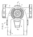
- la figure 2 représente une coupe de dessus, par un plan horizontal, de l'articulation d'accouplement conforme à l'invention,
- la figure 3 représente une coupe de face, par un plan transversal, de l'articulation d'accouplement conforme à l'invention.
- FIG. 1 represents a section through a longitudinal plane of symmetry of a coupling articulation according to the invention,
- FIG. 2 represents a section from above, on a horizontal plane, of the coupling articulation according to the invention,
- FIG. 3 represents a front section, through a transverse plane, of the coupling articulation according to the invention.
Conformément à une caractéristique essentielle, l'articulation d'accouplement entre deux véhicules A, B, notamment ferroviaires, reposant sur un bogie médian (non représenté) entre les deux véhicules et présentant une fonction de rotation et une fonction d'amortissement, est telle que chaque fonction de rotation et d'amortissement est réalisé par des éléments distincts.In accordance with an essential characteristic, the coupling joint between two vehicles A, B, especially rail, resting on a middle bogie (not shown) between the two vehicles and presenting a rotation function and a damping function, is such that each rotation and damping function is made by separate elements.
Comme représenté aux figures 1 à 3, l'articulation
d'accouplement comporte une pièce torique centrale 3,
présentant une surface d'appui tronconique 3A, une rotule 1,
2 comportant une partie conique centrale creuse 1A
s'imbriquant sur la surface d'appui tronconique 3A de la
pièce torique centrale 3, des éléments élastiques 4, un
disque 5 et une vis de maintien 6 comportant un pivot
vertical 6A.As shown in Figures 1 to 3, the joint
coupling comprises a central
La pièce torique centrale 3 comporte en partie
supérieure la surface d'appui tronconique 3A et est reliée
par sa partie inférieure au châssis 9 de la caisse de l'un
des véhicules B.The central
La rotule 1, 2 associe un premier élément 1 de forme générale sphérique à un second élément 2 externe disposé libre en rotation sur le premier élément 1.The ball 1, 2 combines a first element 1 of shape general spherical to a second external element 2 arranged free to rotate on the first element 1.
Les éléments élastiques 4 sont, de préférence au nombre de deux, de forme générale semi-circulaire et sont disposés symétriquement de part et d'autre de la rotule 1, 2 et de l'axe longitudinal du véhicule de manière à prendre appui contre la surface extérieure du second élément 2 de la rotule 1, 2. The elastic elements 4 are, preferably at number of two, generally semicircular and are symmetrically arranged on either side of the ball 1, 2 and the longitudinal axis of the vehicle so as to take support against the external surface of the second element 2 of the ball 1, 2.
Le disque 5 est disposé entre le châssis 9 de la
caisse de l'un des véhicules B et une pièce de support 12 de
l'articulation d'accouplement.The disc 5 is disposed between the
Le disque 5 maintien le second élément 2 de la rotule 1, 2 sur le premier élément 1 de la rotule 1, 2.The disc 5 holds the second element 2 of the ball joint 1, 2 on the first element 1 of the ball joint 1, 2.
La pièce de support 12 est reliée au châssis 9 de la
caisse de l'un des véhicules B et est, par exemple, composée
de plusieurs éléments soudés entre eux.The
La pièce de support 12 supporte la pièce torique
centrale 3 par sa partie inférieure.The
Le pivot vertical 6A de la vis de maintien 6 s'engage
au centre de la pièce torique centrale 3 et est fixé à la
pièce torique centrale 3 grâce à un filetage 3B.The vertical pivot 6A of the retaining
La pièce torique centrale 3 est évidé dans sa partie
inférieure afin de recevoir l'entraínement caisse/bogie 11.The central
La vis de maintien 6 évite tout déboítement de
l'ensemble, par exemple, lors du passage sur de gros défaut
de voie.The retaining
Un capot de protection supérieure 7 et une collerette inférieure 8 évite toutes projections, par exemple de ballast, pouvant détériorer l'articulation d'accouplement.A top protective cover 7 and a flange lower 8 avoids all projections, for example of ballast, which could damage the coupling joint.
Le disque 5 est relié au châssis 10 de la caisse de
l'autre véhicule A.The disc 5 is connected to the
Le disque 5 est indéformable et l'une et l'autre de ses extrémités forme un buttoir.Disc 5 is non-deformable and both its ends form a ridger.
Le disque 5 est calibré en fonction du type de matériel ferroviaire roulant sur lequel il est monté. A titre d'exemple, la tenue de cette pièce varie de 20 kN à 3000 kN.Disc 5 is calibrated according to the type of railway rolling stock on which it is mounted. AT For example, the resistance of this piece varies from 20 kN to 3000 kN.
Le disque 5 peut être réalisée en acier, en alliage au Titane, en alliage d'aluminium ou en matériaux composites.The disc 5 can be made of steel, of alloy with Titanium, aluminum alloy or composite materials.
Les éléments élastiques 4 disposés symétriquement de part et d'autre de la rotule 1, 2 et de l'axe longitudinal du véhicule absorbent l'énergie en assurant une grande souplesse longitudinale. The elastic elements 4 arranged symmetrically on either side of the ball 1, 2 and the longitudinal axis of the vehicle absorb energy by ensuring high longitudinal flexibility.
Les éléments élastiques 4 présentent une grande rigidité transversale.The elastic elements 4 have a large transverse rigidity.
Cette absorption d'énergie se fait dans le sens longitudinal du véhicule plus particulièrement lors des tractions-freinages et accostages et évite tout risque de matage de la rotule 1, 2.This energy absorption is done in the direction longitudinal of the vehicle more particularly during traction braking and docking and avoids any risk of matting of the patella 1, 2.
Claims (9)
- A swivel coupling for coupling together two vehicles (A, B), in particular two rail vehicles, the swivel coupling resting on a shared bogie between said two vehicles and having both a rotation function and a shock-absorbing function, both of which are said swivel coupling being characterized in that each function, namely the rotation function and the shock-absorbing function, is are performed by distinct elements, said swivel coupling being characterized in that it comprises:a ball (1, 2) associating a first element (1) that is spherical in overall shape with a second element (2) that is external and that is disposed to rotate freely on the first element (1), the first element (1) being connected to a support part (9) connected to the underframe of the body of one of the vehicles (B);resilient elements (4) bearing against the outside surface of the second element (2) of the ball; anda disk (5) bearing on the resilient elements (4) and connected to the underframe (10) of the body of the other vehicle (A).
- A swivel coupling according to claim 1, characterized in that said support part (12) supports a toroidal central part (3) having a frustoconical bearing surface (3A), and in that the first element (1) of the ball has a hollow central portion (1A) that fits over the frustoconical bearing surface (3A) of the central part (3).
- A swivel coupling according to claim 1 or claim 2, in which the top portion of the toroidal part (3) is provided with the frustoconical bearing surface (3A), and its bottom portion is connected to said underframe (9).
- A swivel coupling according to claim 2 or claim 3, in which there are two resilient elements (4), and they are semi-circular in overall shape and are disposed symmetrically on either side of the ball (1, 2) and of the longitudinal axis of the vehicle.
- A swivel coupling according to any one of claims 2 to 4, in which the disk (5) is disposed between the underframe (9) of the body of one of the vehicles (B) and the support part (12) for supporting the swivel coupling.
- A swivel coupling according to claim 5, in which the disk (5) holds the second element (2) of the ball (1, 2) on the first element (1 ) of the ball (1, 2).
- A swivel coupling according to any one of claims 2 to 6, in which the support part (12) supports the toroidal central part (3) via the bottom portion thereof.
- A swivel coupling according to any one of claims 2 to 7, in which the vertical pivot (6A) of a holding screw (6) is engaged in the center of the toroidal central part (3), and it is fixed thereto by means of thread (3B).
- A swivel coupling according to any one of claims 2 to 8, in which the bottom portion of the toroidal central part (3) is recessed to receive the body/bogie drive (11).
Applications Claiming Priority (2)
| Application Number | Priority Date | Filing Date | Title |
|---|---|---|---|
| FR9712265 | 1997-10-02 | ||
| FR9712265A FR2769276B1 (en) | 1997-10-02 | 1997-10-02 | COUPLING ARTICULATION |
Publications (2)
| Publication Number | Publication Date |
|---|---|
| EP0906860A1 EP0906860A1 (en) | 1999-04-07 |
| EP0906860B1 true EP0906860B1 (en) | 2003-09-24 |
Family
ID=9511723
Family Applications (1)
| Application Number | Title | Priority Date | Filing Date |
|---|---|---|---|
| EP98402422A Expired - Lifetime EP0906860B1 (en) | 1997-10-02 | 1998-10-01 | Articulated coupling |
Country Status (8)
| Country | Link |
|---|---|
| US (1) | US6234702B1 (en) |
| EP (1) | EP0906860B1 (en) |
| JP (1) | JP4155636B2 (en) |
| KR (1) | KR100540406B1 (en) |
| CA (1) | CA2246000C (en) |
| DE (1) | DE69818387T9 (en) |
| ES (1) | ES2209081T3 (en) |
| FR (1) | FR2769276B1 (en) |
Families Citing this family (12)
| Publication number | Priority date | Publication date | Assignee | Title |
|---|---|---|---|---|
| FR2769276B1 (en) * | 1997-10-02 | 2002-10-11 | Gec Alsthom Transport Sa | COUPLING ARTICULATION |
| DE19919536A1 (en) * | 1999-04-29 | 2000-11-02 | Alstom Lhb Gmbh | Articulated coupling for vehicle units of rail vehicles |
| DE10139970A1 (en) * | 2001-08-14 | 2003-02-27 | Ina Schaeffler Kg | Linking unit for two adjacent body structures of multiple body rail vehicles, comprises two concentrically nested spherical pivot bearings whose inner elements are joined to different body structures |
| US20050247346A1 (en) * | 2004-05-07 | 2005-11-10 | Edward Pentz | Hose mount |
| FR2901763B1 (en) * | 2006-06-02 | 2014-08-08 | Alstom Transport Sa | STRUCTURAL ASSEMBLY OF END OF RAIL VEHICLE CAR CASE. |
| FR2945266A1 (en) * | 2009-05-06 | 2010-11-12 | Alstom Transport Sa | COUPLING JOINT BETWEEN A FIRST CAR AND A SECOND CAR OF A VEHICLE, IN PARTICULAR RAILWAY VEHICLE |
| DE102010046495B3 (en) * | 2010-09-24 | 2011-11-10 | Hübner GmbH | Joint of an articulated vehicle |
| JP5725779B2 (en) * | 2010-09-24 | 2015-05-27 | 新日鐵住金株式会社 | Shinkansen vehicle connection device and removal method |
| CN102431767B (en) * | 2011-12-22 | 2013-12-18 | 江阴大地装备股份有限公司 | Support buffer seat |
| FR2987332B1 (en) * | 2012-02-28 | 2014-11-28 | Alstom Transport Sa | DEVICE FOR COUPLING TWO VEHICLES, ESPECIALLY RAIL VEHICLES, AND CORRESPONDING VEHICLE ASSEMBLY. |
| US9701323B2 (en) | 2015-04-06 | 2017-07-11 | Bedloe Industries Llc | Railcar coupler |
| CN107117181A (en) * | 2017-05-02 | 2017-09-01 | 江西省浩燃冶金设备有限责任公司 | A kind of rock feeder |
Family Cites Families (15)
| Publication number | Priority date | Publication date | Assignee | Title |
|---|---|---|---|---|
| DE1040063B (en) * | 1954-12-11 | 1958-10-02 | Maschf Augsburg Nuernberg Ag | Device for linking a cradle-free bogie to the car body of rail vehicles |
| US2886299A (en) * | 1956-04-30 | 1959-05-12 | Union Carbide Corp | Bore mining apparatus having means to measure the angle between units thereof |
| FR2348092A1 (en) * | 1976-04-16 | 1977-11-10 | Mte | Pivot between railway vehicle bodies - has vertical pivot in two rings, one on wheeled support and other on joints round horizontal axis |
| FR2631917B1 (en) * | 1988-05-24 | 1990-08-10 | Alsthom | COUPLING ARTICULATION OF TWO RAIL VEHICLES |
| US5033722A (en) * | 1989-08-21 | 1991-07-23 | Caterpillar Inc. | Resilient mount assembly |
| US5271678A (en) * | 1989-12-29 | 1993-12-21 | Caoutchouc Manufacture Et Plastiques S.A. | Elastic bearing |
| FR2656580B1 (en) * | 1989-12-29 | 1992-04-03 | Caoutchouc Manuf Plastique | COUPLING ARTICULATION BETWEEN RAIL VEHICLES OF ARTICULATED ROW. |
| DE4305614A1 (en) * | 1993-02-24 | 1994-08-25 | Linke Hofmann Busch | Articulated connection for the articulated connection of vehicle parts of a multi-unit rail vehicle |
| CA2120314C (en) * | 1993-12-13 | 1999-05-04 | David W. Daugherty, Jr. | Lubricating apparatus for articulated coupling arrangement |
| FR2716149B1 (en) | 1994-02-15 | 1996-03-29 | Gec Alsthom Transport Sa | Coupling joint and energy absorption method between two railway vehicles. |
| US5507400A (en) * | 1994-06-01 | 1996-04-16 | National Castings Incorporated | Slackless drawbar or coupler with swivel mounting |
| US5520295A (en) * | 1994-07-18 | 1996-05-28 | Hansen Inc. | Articulated rail car connector |
| DE9420230U1 (en) * | 1994-12-21 | 1995-03-23 | AEG Schienenfahrzeuge GmbH, 90461 Nürnberg | Articulated bearings for rail vehicles |
| US5809898A (en) * | 1997-01-30 | 1998-09-22 | Amsted Industries Incorporated | Ring seat removal system for a railcar articulate connector |
| FR2769276B1 (en) * | 1997-10-02 | 2002-10-11 | Gec Alsthom Transport Sa | COUPLING ARTICULATION |
-
1997
- 1997-10-02 FR FR9712265A patent/FR2769276B1/en not_active Expired - Lifetime
-
1998
- 1998-09-29 JP JP27583398A patent/JP4155636B2/en not_active Expired - Fee Related
- 1998-10-01 US US09/164,572 patent/US6234702B1/en not_active Expired - Lifetime
- 1998-10-01 DE DE69818387T patent/DE69818387T9/en active Active
- 1998-10-01 CA CA002246000A patent/CA2246000C/en not_active Expired - Lifetime
- 1998-10-01 EP EP98402422A patent/EP0906860B1/en not_active Expired - Lifetime
- 1998-10-01 ES ES98402422T patent/ES2209081T3/en not_active Expired - Lifetime
- 1998-10-02 KR KR1019980041640A patent/KR100540406B1/en not_active Expired - Lifetime
Also Published As
| Publication number | Publication date |
|---|---|
| FR2769276B1 (en) | 2002-10-11 |
| US6234702B1 (en) | 2001-05-22 |
| KR100540406B1 (en) | 2006-04-21 |
| ES2209081T3 (en) | 2004-06-16 |
| CA2246000A1 (en) | 1999-04-02 |
| FR2769276A1 (en) | 1999-04-09 |
| DE69818387T9 (en) | 2004-10-07 |
| EP0906860A1 (en) | 1999-04-07 |
| DE69818387D1 (en) | 2003-10-30 |
| DE69818387T2 (en) | 2004-07-01 |
| KR19990036845A (en) | 1999-05-25 |
| JP4155636B2 (en) | 2008-09-24 |
| JPH11165636A (en) | 1999-06-22 |
| CA2246000C (en) | 2005-04-12 |
Similar Documents
| Publication | Publication Date | Title |
|---|---|---|
| EP0343482B1 (en) | Coupling articulation between two railway vehicles | |
| EP0906860B1 (en) | Articulated coupling | |
| EP0667271B1 (en) | Articulated coupling and method for energy absorption between two railway vehicles | |
| CA2681344C (en) | Primary suspension device for a railway vehicle bogie | |
| CA2682931C (en) | Bogie for railway vehicle | |
| FR2511962A1 (en) | WHEEL TRAIN FOR A STABILIZED RAIL VEHICLE | |
| FR2636569A1 (en) | ||
| EP0409128B1 (en) | Articulated bogie for rail vehicles | |
| FR2548618A1 (en) | RAIL VEHICLE SUSPENSION | |
| CA2736696C (en) | Motorized bogie | |
| EP0279245A1 (en) | Connection device between two railway vehicles | |
| EP0277059B1 (en) | Rail vehicle having its load distributed among the four axles which are rotatable relative to the superstructure | |
| FR2645800A1 (en) | Set of wheels, particularly of the MacPherson type with a lower filtering cross-member | |
| FR2572348A1 (en) | Orientable guide axle assembly for vehicles on rails | |
| FR2770456A1 (en) | REAR AXLE COMPRISING A DEVICE FOR JOINING AN OSCILLATING ARM PULLING ON A STRUCTURE OF A MOTOR VEHICLE | |
| FR3106557A1 (en) | Bogie for independent wheel vehicle and associated vehicle | |
| EP4116165B1 (en) | Chain of semi-trailer vehicles and associated articulated train | |
| BE898075A (en) | TWO AXLE BOGIE FOR RAIL VEHICLES OR TRAMWAYS AND RAIL VEHICLES OR TRAMWAYS USING THE SAME. | |
| FR2562859A1 (en) | Device for mounting a swivelling axle intended to support the adjacent ends of two coaches of urban railway stock and coach sets composed of such coaches | |
| FR2610269A1 (en) | Device for linking between two rail vehicles | |
| FR2684948A1 (en) | GUIDE ASSEMBLY OF A MOUNTED AXLE, PARTICULARLY FOR RAILWAY VEHICLES WITH BOGIES. | |
| FR2666779A1 (en) | IMPROVED WAGON BOGIE AND CROSSING FOR OUTBOARD SUPPORT OF A WAGON BODY. | |
| FR2491850A1 (en) | Self aligning railway bogie - has flexible parts between equalisers and axle boxes and sole bar to giVe limited axle movements | |
| EP0061944A1 (en) | Set of wheels for a vehicle | |
| BE624383A (en) |
Legal Events
| Date | Code | Title | Description |
|---|---|---|---|
| PUAI | Public reference made under article 153(3) epc to a published international application that has entered the european phase |
Free format text: ORIGINAL CODE: 0009012 |
|
| AK | Designated contracting states |
Kind code of ref document: A1 Designated state(s): AT BE CH CY DE DK ES FI FR GB GR IE IT LI LU MC NL PT SE |
|
| AX | Request for extension of the european patent |
Free format text: AL;LT;LV;MK;RO;SI |
|
| AKX | Designation fees paid | ||
| RBV | Designated contracting states (corrected) |
Designated state(s): DE ES IT |
|
| 17P | Request for examination filed |
Effective date: 19991007 |
|
| R17P | Request for examination filed (corrected) |
Effective date: 19991007 |
|
| 17Q | First examination report despatched |
Effective date: 20020617 |
|
| GRAH | Despatch of communication of intention to grant a patent |
Free format text: ORIGINAL CODE: EPIDOS IGRA |
|
| GRAS | Grant fee paid |
Free format text: ORIGINAL CODE: EPIDOSNIGR3 |
|
| GRAA | (expected) grant |
Free format text: ORIGINAL CODE: 0009210 |
|
| AK | Designated contracting states |
Kind code of ref document: B1 Designated state(s): DE ES IT |
|
| REF | Corresponds to: |
Ref document number: 69818387 Country of ref document: DE Date of ref document: 20031030 Kind code of ref document: P |
|
| RAP2 | Party data changed (patent owner data changed or rights of a patent transferred) |
Owner name: ALSTOM TRANSPORT S.A. |
|
| REG | Reference to a national code |
Ref country code: ES Ref legal event code: FG2A Ref document number: 2209081 Country of ref document: ES Kind code of ref document: T3 |
|
| PLBE | No opposition filed within time limit |
Free format text: ORIGINAL CODE: 0009261 |
|
| STAA | Information on the status of an ep patent application or granted ep patent |
Free format text: STATUS: NO OPPOSITION FILED WITHIN TIME LIMIT |
|
| 26N | No opposition filed |
Effective date: 20040625 |
|
| REG | Reference to a national code |
Ref country code: HK Ref legal event code: WD Ref document number: 1020433 Country of ref document: HK |
|
| REG | Reference to a national code |
Ref country code: ES Ref legal event code: PC2A Owner name: ALSTOM TRANSPORT TECHNOLOGIES Effective date: 20140211 |
|
| REG | Reference to a national code |
Ref country code: DE Ref legal event code: R082 Ref document number: 69818387 Country of ref document: DE Representative=s name: DREISS PATENTANWAELTE PARTG MBB, DE Effective date: 20140213 Ref country code: DE Ref legal event code: R081 Ref document number: 69818387 Country of ref document: DE Owner name: ALSTOM TRANSPORT TECHNOLOGIES, FR Free format text: FORMER OWNER: ALSTOM TRANSPORT S.A., PARIS, FR Effective date: 20140213 |
|
| REG | Reference to a national code |
Ref country code: DE Ref legal event code: R082 Ref document number: 69818387 Country of ref document: DE Representative=s name: DREISS PATENTANWAELTE PARTG MBB, DE Ref country code: DE Ref legal event code: R081 Ref document number: 69818387 Country of ref document: DE Owner name: ALSTOM TRANSPORT TECHNOLOGIES, FR Free format text: FORMER OWNER: ALSTOM TRANSPORT TECHNOLOGIES, LEVALLOIS-PERRET, FR |
|
| PGFP | Annual fee paid to national office [announced via postgrant information from national office to epo] |
Ref country code: DE Payment date: 20171019 Year of fee payment: 20 |
|
| PGFP | Annual fee paid to national office [announced via postgrant information from national office to epo] |
Ref country code: IT Payment date: 20171023 Year of fee payment: 20 Ref country code: ES Payment date: 20171121 Year of fee payment: 20 |
|
| REG | Reference to a national code |
Ref country code: DE Ref legal event code: R071 Ref document number: 69818387 Country of ref document: DE |
|
| REG | Reference to a national code |
Ref country code: ES Ref legal event code: FD2A Effective date: 20200806 |
|
| PG25 | Lapsed in a contracting state [announced via postgrant information from national office to epo] |
Ref country code: ES Free format text: LAPSE BECAUSE OF EXPIRATION OF PROTECTION Effective date: 20181002 |