EP0906860B1 - Gelenkkupplung - Google Patents
Gelenkkupplung Download PDFInfo
- Publication number
- EP0906860B1 EP0906860B1 EP98402422A EP98402422A EP0906860B1 EP 0906860 B1 EP0906860 B1 EP 0906860B1 EP 98402422 A EP98402422 A EP 98402422A EP 98402422 A EP98402422 A EP 98402422A EP 0906860 B1 EP0906860 B1 EP 0906860B1
- Authority
- EP
- European Patent Office
- Prior art keywords
- swivel coupling
- vehicles
- ball
- coupling according
- underframe
- Prior art date
- Legal status (The legal status is an assumption and is not a legal conclusion. Google has not performed a legal analysis and makes no representation as to the accuracy of the status listed.)
- Expired - Lifetime
Links
- 230000008878 coupling Effects 0.000 title claims description 38
- 238000010168 coupling process Methods 0.000 title claims description 38
- 238000005859 coupling reaction Methods 0.000 title claims description 38
- 230000000284 resting effect Effects 0.000 claims description 4
- 238000013016 damping Methods 0.000 description 4
- 210000004417 patella Anatomy 0.000 description 2
- 230000000452 restraining effect Effects 0.000 description 2
- 238000005096 rolling process Methods 0.000 description 2
- 229910000838 Al alloy Inorganic materials 0.000 description 1
- 229910000831 Steel Inorganic materials 0.000 description 1
- RTAQQCXQSZGOHL-UHFFFAOYSA-N Titanium Chemical compound [Ti] RTAQQCXQSZGOHL-UHFFFAOYSA-N 0.000 description 1
- 238000010521 absorption reaction Methods 0.000 description 1
- 239000000956 alloy Substances 0.000 description 1
- 229910045601 alloy Inorganic materials 0.000 description 1
- 239000002131 composite material Substances 0.000 description 1
- 230000007547 defect Effects 0.000 description 1
- 229910052751 metal Inorganic materials 0.000 description 1
- 239000002184 metal Substances 0.000 description 1
- 238000003032 molecular docking Methods 0.000 description 1
- 230000000750 progressive effect Effects 0.000 description 1
- 230000001681 protective effect Effects 0.000 description 1
- 239000010959 steel Substances 0.000 description 1
- 239000010936 titanium Substances 0.000 description 1
- 229910052719 titanium Inorganic materials 0.000 description 1
Images

Classifications
-
- B—PERFORMING OPERATIONS; TRANSPORTING
- B61—RAILWAYS
- B61G—COUPLINGS; DRAUGHT AND BUFFING APPLIANCES
- B61G1/00—Couplings comprising interengaging parts of different shape or form and having links, bars, pins, shackles, or hooks as coupling means
-
- B—PERFORMING OPERATIONS; TRANSPORTING
- B61—RAILWAYS
- B61F—RAIL VEHICLE SUSPENSIONS, e.g. UNDERFRAMES, BOGIES OR ARRANGEMENTS OF WHEEL AXLES; RAIL VEHICLES FOR USE ON TRACKS OF DIFFERENT WIDTH; PREVENTING DERAILING OF RAIL VEHICLES; WHEEL GUARDS, OBSTRUCTION REMOVERS OR THE LIKE FOR RAIL VEHICLES
- B61F5/00—Constructional details of bogies; Connections between bogies and vehicle underframes; Arrangements or devices for adjusting or allowing self-adjustment of wheel axles or bogies when rounding curves
- B61F5/02—Arrangements permitting limited transverse relative movements between vehicle underframe or bolster and bogie; Connections between underframes and bogies
- B61F5/16—Centre bearings or other swivel connections between underframes and bolsters or bogies
- B61F5/20—Centre bearings or other swivel connections between underframes and bolsters or bogies with springs allowing transverse movements
-
- B—PERFORMING OPERATIONS; TRANSPORTING
- B61—RAILWAYS
- B61F—RAIL VEHICLE SUSPENSIONS, e.g. UNDERFRAMES, BOGIES OR ARRANGEMENTS OF WHEEL AXLES; RAIL VEHICLES FOR USE ON TRACKS OF DIFFERENT WIDTH; PREVENTING DERAILING OF RAIL VEHICLES; WHEEL GUARDS, OBSTRUCTION REMOVERS OR THE LIKE FOR RAIL VEHICLES
- B61F3/00—Types of bogies
- B61F3/12—Types of bogies specially modified for carrying adjacent vehicle bodies of articulated trains
-
- B—PERFORMING OPERATIONS; TRANSPORTING
- B61—RAILWAYS
- B61G—COUPLINGS; DRAUGHT AND BUFFING APPLIANCES
- B61G5/00—Couplings for special purposes not otherwise provided for
- B61G5/02—Couplings for special purposes not otherwise provided for for coupling articulated trains, locomotives and tenders or the bogies of a vehicle; Coupling by means of a single coupling bar; Couplings preventing or limiting relative lateral movement of vehicles
-
- Y—GENERAL TAGGING OF NEW TECHNOLOGICAL DEVELOPMENTS; GENERAL TAGGING OF CROSS-SECTIONAL TECHNOLOGIES SPANNING OVER SEVERAL SECTIONS OF THE IPC; TECHNICAL SUBJECTS COVERED BY FORMER USPC CROSS-REFERENCE ART COLLECTIONS [XRACs] AND DIGESTS
- Y10—TECHNICAL SUBJECTS COVERED BY FORMER USPC
- Y10T—TECHNICAL SUBJECTS COVERED BY FORMER US CLASSIFICATION
- Y10T403/00—Joints and connections
- Y10T403/32—Articulated members
- Y10T403/32114—Articulated members including static joint
- Y10T403/32213—Articulate joint is a swivel
-
- Y—GENERAL TAGGING OF NEW TECHNOLOGICAL DEVELOPMENTS; GENERAL TAGGING OF CROSS-SECTIONAL TECHNOLOGIES SPANNING OVER SEVERAL SECTIONS OF THE IPC; TECHNICAL SUBJECTS COVERED BY FORMER USPC CROSS-REFERENCE ART COLLECTIONS [XRACs] AND DIGESTS
- Y10—TECHNICAL SUBJECTS COVERED BY FORMER USPC
- Y10T—TECHNICAL SUBJECTS COVERED BY FORMER US CLASSIFICATION
- Y10T403/00—Joints and connections
- Y10T403/32—Articulated members
- Y10T403/32606—Pivoted
- Y10T403/32614—Pivoted including circumferential biasing or damping means
-
- Y—GENERAL TAGGING OF NEW TECHNOLOGICAL DEVELOPMENTS; GENERAL TAGGING OF CROSS-SECTIONAL TECHNOLOGIES SPANNING OVER SEVERAL SECTIONS OF THE IPC; TECHNICAL SUBJECTS COVERED BY FORMER USPC CROSS-REFERENCE ART COLLECTIONS [XRACs] AND DIGESTS
- Y10—TECHNICAL SUBJECTS COVERED BY FORMER USPC
- Y10T—TECHNICAL SUBJECTS COVERED BY FORMER US CLASSIFICATION
- Y10T403/00—Joints and connections
- Y10T403/45—Flexibly connected rigid members
- Y10T403/455—Elastomer interposed between radially spaced members
- Y10T403/458—Composite bushing with elastomeric component
Definitions
- the present invention relates to connection between vehicles, in particular rail, constituting an articulated oar, in general, and carries, more particularly on a coupling joint between two vehicles, notably rail vehicles.
- Document DE-AS-1 040 063 discloses a joint coupling between two vehicles with a function of rotation and a damping function, each function of rotation and coupling being achieved by elements distinct.
- a joint presents the disadvantage of not allowing angular deflections around the longitudinal axis and is therefore not suitable for tilting vehicle.
- a toric joint element ensures the joint between a soleplate and the O-ring.
- This toric joint element is a structure composed of successive and multiple layers of metal and rubber which may be of different stiffnesses and progressive.
- a major drawback of the joint coupling of two railway vehicles described in this prior art document is that it only allows low angular deflections.
- the coupling joint of two vehicles railway described in this document of the prior art has as a disadvantage of being rigid and therefore of imposing a twisting of tilting vehicle bodies during passage of curved tracks.
- an object of the invention is a joint coupling of two vehicles, especially rail vehicles, supporting the deflection around the longitudinal axis without produce a restraining force in order to avoid any twists checkout.
- An advantage of the coupling joint of two rail vehicles the invention is to be extra-flat due to its small size.
- Another advantage of the coupling joint of two railway vehicles of the invention is that it can be integrated on pendulum articulated rolling stock or not pendulum.
- Another advantage of the coupling joint of two rail vehicles the invention is to allow to lower the level of the traffic floor by one value of the order of 200 mm.
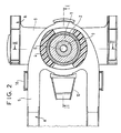
- the coupling joint between two vehicles A, B, especially rail, resting on a middle bogie (not shown) between the two vehicles and presenting a rotation function and a damping function is such that each rotation and damping function is made by separate elements.
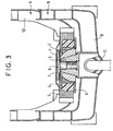
- the joint coupling comprises a central toric part 3, having a frustoconical bearing surface 3A, a ball joint 1, 2 having a hollow central conical part 1A nesting on the frustoconical bearing surface 3A of the central O-ring 3, elastic elements 4, a disc 5 and a retaining screw 6 comprising a pivot vertical 6A.
- the central toric part 3 partly comprises the tapered support surface 3A and is connected by its lower part to the chassis 9 of the body of one vehicles B.
- the ball 1, 2 combines a first element 1 of shape general spherical to a second external element 2 arranged free to rotate on the first element 1.
- the elastic elements 4 are, preferably at number of two, generally semicircular and are symmetrically arranged on either side of the ball 1, 2 and the longitudinal axis of the vehicle so as to take support against the external surface of the second element 2 of the ball 1, 2.
- the disc 5 is disposed between the chassis 9 of the body of one of the vehicles B and a support piece 12 of the coupling joint.
- the disc 5 holds the second element 2 of the ball joint 1, 2 on the first element 1 of the ball joint 1, 2.
- the support piece 12 is connected to the chassis 9 of the body of one of the vehicles B and is, for example, composed of several elements welded together.
- the support piece 12 supports the toric piece central 3 by its lower part.
- the vertical pivot 6A of the retaining screw 6 engages in the center of the central toric part 3 and is fixed to the central toric part 3 thanks to a 3B thread.
- the central toric part 3 is hollowed out in its part lower to receive the body / bogie drive 11.
- the retaining screw 6 avoids any dislocation of the whole, for example, when going over a big defect of track.
- a top protective cover 7 and a flange lower 8 avoids all projections, for example of ballast, which could damage the coupling joint.
- the disc 5 is connected to the chassis 10 of the body of the other vehicle A.
- Disc 5 is non-deformable and both its ends form a ridger.
- Disc 5 is calibrated according to the type of railway rolling stock on which it is mounted. AT For example, the resistance of this piece varies from 20 kN to 3000 kN.
- the disc 5 can be made of steel, of alloy with Titanium, aluminum alloy or composite materials.
- the elastic elements 4 arranged symmetrically on either side of the ball 1, 2 and the longitudinal axis of the vehicle absorb energy by ensuring high longitudinal flexibility.
- the elastic elements 4 have a large transverse rigidity.
- This energy absorption is done in the direction longitudinal of the vehicle more particularly during traction braking and docking and avoids any risk of matting of the patella 1, 2.
Landscapes
- Engineering & Computer Science (AREA)
- Mechanical Engineering (AREA)
- Vibration Prevention Devices (AREA)
- Vibration Dampers (AREA)
- Pivots And Pivotal Connections (AREA)
- Sliding-Contact Bearings (AREA)
- Rolling Contact Bearings (AREA)
- Compositions Of Oxide Ceramics (AREA)
- Platform Screen Doors And Railroad Systems (AREA)
Claims (9)
- Gelenkkupplung zwischen zwei Fahrzeugen A, B, insbesondere Schienenfahrzeugen, die auf einem Drehgestell in der Mitte zwischen den genannten Fahrzeugen ruht,
wobei die genannte Gelenkkupplung eine Drehfunktion und eine Dämpfüngsnmktion besitzt, wobei jede Drehfunktion und Dämpfungsfunktion durch unterschiedliche Elemente ausgeführt wird, dadurch gekennzeichnet, dass sie folgendes aufweist:ein Kugelgelenk (1, 2), das ein erstes, allgemein kugelformiges Element (1) mit einem zweiten, externen Element (2) verbindet, das frei drehend auf dem ersten Element (1) angeordnet ist, wobei das erste Element (1) mit einem Stützteil (12) verbunden ist, das mit dem Untergestell (9) des Wagenkastens eines der Fahrzeuge B verbunden ist,elastische Elemente (4), die sich gegen die Außenfläche des zweiten Elementes (2) des Kugelgelenks abstützen,eine Scheibe (5), die sich auf den elastischen Elementen (4) abstützt, und die mit dem Untergestell (10) des Wagenkastens des anderen Fahrzeugs A verbunden ist. - Gelenkkupplung nach Anspruch 1, dadurch gekennzeichnet, dass das genannte Stützteil (12) ein mittleres, wulstförmiges Teil (3) stützt, das eine kegelstumpfartige Auflagefläche (3A) besitzt und dass das erste Element (1) des Kugelgelenks einen hohlen Abschnitt in der Mitte (1A) besitzt, der die kegelstumpfartige Auflagefläche (3A) des Mittelteils (3) überlappt.
- Gelenkkupplung nach einem der vorhergehenden Ansprüche, wobei das wulstförmige Teil in der Mitte (3) in seinem oberen Teil die kegelstumpfartige Auflagefläche (3A) besitzt, und mit seinem unteren Teil mit dem genannten Untergestell (9) verbunden ist.
- Gelenkkupplung nach einem der vorhergehenden Ansprüche 2 und 3, wobei es sich bei den elastischen Elementen (4) um zwei, allgemein halbkreisförmige Elemente handelt, die symmetrisch zu beiden Seiten des Kugelgelenks (1, 2) und der Längsachse des Fahrzeugs angeordnet sind.
- Gelenkkupplung nach einem der vorhergehenden Ansprüche 2 bis 4, wobei die Scheibe (5) zwischen dem Untergestell (9) des Wagenkastens eines der Fahrzeuge B und dem Stützteil (12) der Gelenkkupplung angeordnet ist.
- Gelenkkupplung nach Anspruch 5, wobei die Scheibe (5) das zweite Element (2) des Kugelgelenks (1,2) auf dem ersten Element (1) des Kugelgelenks (1, 2) hält.
- Gelenkkupplung nach einem der vorhergehenden Ansprüche 2 bis 6, wobei das Stützteil (12) das mittlere, wulstförmige Teil (3) an seinem Unterteil aufnimmt.
- Gelenkkupplung nach einem der vorhergehenden Ansprüche 2 bis 7, wobei der vertikale Drehzapfen (6A) einer Sicherungsschraube (6) in den Mittelpunkt des mittleren, wulstförmigen Teils (3) eingreift und mit einem Gewinde (3B) am mittleren, wulstförmigen Teil (3) befestigt ist.
- Gelenkkupplung nach einem der vorhergehenden Ansprüche 2 bis 8, wobei das mittlere, wulstförmige Teil (3) für die Aufnahme des Antriebs Untergestell / Drehgestell (11) in seinem Unterteil durchbrochen ist.
Applications Claiming Priority (2)
| Application Number | Priority Date | Filing Date | Title |
|---|---|---|---|
| FR9712265A FR2769276B1 (fr) | 1997-10-02 | 1997-10-02 | Articulation d'accouplement |
| FR9712265 | 1997-10-02 |
Publications (2)
| Publication Number | Publication Date |
|---|---|
| EP0906860A1 EP0906860A1 (de) | 1999-04-07 |
| EP0906860B1 true EP0906860B1 (de) | 2003-09-24 |
Family
ID=9511723
Family Applications (1)
| Application Number | Title | Priority Date | Filing Date |
|---|---|---|---|
| EP98402422A Expired - Lifetime EP0906860B1 (de) | 1997-10-02 | 1998-10-01 | Gelenkkupplung |
Country Status (8)
| Country | Link |
|---|---|
| US (1) | US6234702B1 (de) |
| EP (1) | EP0906860B1 (de) |
| JP (1) | JP4155636B2 (de) |
| KR (1) | KR100540406B1 (de) |
| CA (1) | CA2246000C (de) |
| DE (1) | DE69818387T9 (de) |
| ES (1) | ES2209081T3 (de) |
| FR (1) | FR2769276B1 (de) |
Families Citing this family (12)
| Publication number | Priority date | Publication date | Assignee | Title |
|---|---|---|---|---|
| FR2769276B1 (fr) * | 1997-10-02 | 2002-10-11 | Gec Alsthom Transport Sa | Articulation d'accouplement |
| DE19919536A1 (de) * | 1999-04-29 | 2000-11-02 | Alstom Lhb Gmbh | Gelenkkupplung für Fahrzeugeinheiten von Schienenfahrzeugen |
| DE10139970A1 (de) * | 2001-08-14 | 2003-02-27 | Ina Schaeffler Kg | Gelenkanordnung |
| US20050247346A1 (en) * | 2004-05-07 | 2005-11-10 | Edward Pentz | Hose mount |
| FR2901763B1 (fr) | 2006-06-02 | 2014-08-08 | Alstom Transport Sa | Ensemble structurel d'extremite de caisse de voiture ferroviaire. |
| FR2945266A1 (fr) * | 2009-05-06 | 2010-11-12 | Alstom Transport Sa | Articulation d'accouplement entre une premiere voiture et une seconde voiture d'un vehicule notamment ferroviaire |
| DE102010046495B3 (de) * | 2010-09-24 | 2011-11-10 | Hübner GmbH | Gelenk eines Gelenkfahrzeugs |
| JP5725779B2 (ja) * | 2010-09-24 | 2015-05-27 | 新日鐵住金株式会社 | 新幹線車両用連結装置及び取外し方法 |
| CN102431767B (zh) * | 2011-12-22 | 2013-12-18 | 江阴大地装备股份有限公司 | 一种支承缓冲座 |
| FR2987332B1 (fr) * | 2012-02-28 | 2014-11-28 | Alstom Transport Sa | Dispositif d'accouplement de deux vehicules, notamment ferroviaires, et ensemble de vehicules correspondant. |
| US9701323B2 (en) | 2015-04-06 | 2017-07-11 | Bedloe Industries Llc | Railcar coupler |
| CN107117181A (zh) * | 2017-05-02 | 2017-09-01 | 江西省浩燃冶金设备有限责任公司 | 一种给矿机 |
Family Cites Families (15)
| Publication number | Priority date | Publication date | Assignee | Title |
|---|---|---|---|---|
| DE1040063B (de) * | 1954-12-11 | 1958-10-02 | Maschf Augsburg Nuernberg Ag | Einrichtung zum Anlenken eines wiegenlosen Drehgestells an den Wagenkasten von Schienenfahrzeugen |
| US2886299A (en) * | 1956-04-30 | 1959-05-12 | Union Carbide Corp | Bore mining apparatus having means to measure the angle between units thereof |
| FR2348092A1 (fr) * | 1976-04-16 | 1977-11-10 | Mte | Dispositif d'articulation entre deux caisses et un train roulant commun |
| FR2631917B1 (fr) * | 1988-05-24 | 1990-08-10 | Alsthom | Articulation d'accouplement de deux vehicules ferroviaires |
| US5033722A (en) * | 1989-08-21 | 1991-07-23 | Caterpillar Inc. | Resilient mount assembly |
| US5271678A (en) * | 1989-12-29 | 1993-12-21 | Caoutchouc Manufacture Et Plastiques S.A. | Elastic bearing |
| FR2656580B1 (fr) * | 1989-12-29 | 1992-04-03 | Caoutchouc Manuf Plastique | Articulation d'accouplement entre vehicules ferroviaires de rame articulee. |
| DE4305614A1 (de) * | 1993-02-24 | 1994-08-25 | Linke Hofmann Busch | Gelenkverbindung zum gelenkigen Verbinden von Fahrzeugteilen eines mehrgliedrigen Schienenfahrzeugs |
| CA2120314C (en) * | 1993-12-13 | 1999-05-04 | David W. Daugherty, Jr. | Lubricating apparatus for articulated coupling arrangement |
| FR2716149B1 (fr) * | 1994-02-15 | 1996-03-29 | Gec Alsthom Transport Sa | Articulation d'accouplement et procédé d'absorption d'énergie entre deux véhicules ferroviaires. |
| US5507400A (en) * | 1994-06-01 | 1996-04-16 | National Castings Incorporated | Slackless drawbar or coupler with swivel mounting |
| US5520295A (en) * | 1994-07-18 | 1996-05-28 | Hansen Inc. | Articulated rail car connector |
| DE9420230U1 (de) * | 1994-12-21 | 1995-03-23 | AEG Schienenfahrzeuge GmbH, 90461 Nürnberg | Gelenklagerung für Schienenfahrzeuge |
| US5809898A (en) * | 1997-01-30 | 1998-09-22 | Amsted Industries Incorporated | Ring seat removal system for a railcar articulate connector |
| FR2769276B1 (fr) * | 1997-10-02 | 2002-10-11 | Gec Alsthom Transport Sa | Articulation d'accouplement |
-
1997
- 1997-10-02 FR FR9712265A patent/FR2769276B1/fr not_active Expired - Lifetime
-
1998
- 1998-09-29 JP JP27583398A patent/JP4155636B2/ja not_active Expired - Fee Related
- 1998-10-01 US US09/164,572 patent/US6234702B1/en not_active Expired - Lifetime
- 1998-10-01 ES ES98402422T patent/ES2209081T3/es not_active Expired - Lifetime
- 1998-10-01 EP EP98402422A patent/EP0906860B1/de not_active Expired - Lifetime
- 1998-10-01 DE DE69818387T patent/DE69818387T9/de active Active
- 1998-10-01 CA CA002246000A patent/CA2246000C/fr not_active Expired - Lifetime
- 1998-10-02 KR KR1019980041640A patent/KR100540406B1/ko not_active Expired - Lifetime
Also Published As
| Publication number | Publication date |
|---|---|
| EP0906860A1 (de) | 1999-04-07 |
| FR2769276B1 (fr) | 2002-10-11 |
| US6234702B1 (en) | 2001-05-22 |
| CA2246000A1 (fr) | 1999-04-02 |
| JP4155636B2 (ja) | 2008-09-24 |
| ES2209081T3 (es) | 2004-06-16 |
| DE69818387T2 (de) | 2004-07-01 |
| KR100540406B1 (ko) | 2006-04-21 |
| KR19990036845A (ko) | 1999-05-25 |
| FR2769276A1 (fr) | 1999-04-09 |
| DE69818387T9 (de) | 2004-10-07 |
| CA2246000C (fr) | 2005-04-12 |
| DE69818387D1 (de) | 2003-10-30 |
| JPH11165636A (ja) | 1999-06-22 |
Similar Documents
| Publication | Publication Date | Title |
|---|---|---|
| EP0343482B1 (de) | Gelenkkupplung zwischen zwei Schienenfahrzeugen | |
| EP0906860B1 (de) | Gelenkkupplung | |
| EP0667271B1 (de) | Gelenkige Kupplung und Verfahren zur Absorption von Energie zwischen zwei Eisenbahnfahrzeugen | |
| CA2681344C (fr) | Dispositif de suspension primaire d'un bogie de vehicule ferroviaire | |
| CA2682931C (fr) | Bogie pour vehicule ferroviaire | |
| FR2511962A1 (fr) | Train de roues pour vehicule ferroviaire stabilise | |
| FR2636569A1 (de) | ||
| EP0409128B1 (de) | Gelenkdrehgestell für Schienenfahrzeuge | |
| FR2548618A1 (fr) | Suspension de vehicule ferroviaire | |
| CA2736696C (fr) | Bogie moteur | |
| EP0279245A1 (de) | Verbindungseinrichtung zwischen zwei Schienenfahrzeugen | |
| EP0277059B1 (de) | Schienenfahrzeug mit Lastverteilung auf die vier bezüglich des Aufbaus einstellbaren Achsen | |
| FR2645800A1 (fr) | Train de roues notamment du type mac-pherson a traverse inferieure de filtrage | |
| FR2572348A1 (fr) | Ensemble d'essieu orientable guide pour vehicules sur rails | |
| FR2770456A1 (fr) | Train arriere comportant un dispositif d'articulation d'un bras oscillant tire sur une structure d'un vehicule automobile | |
| FR3106557A1 (fr) | Bogie pour véhicule à roues indépendantes et véhicule associé | |
| EP4116165B1 (de) | Kette von sattelschlepperfahrzeugen und entsprechende gelenkzuggarnitur | |
| BE898075A (fr) | Bogie a deux essieux pour vehicules ferroviaires ou tramways et vehicules ferroviaires ou tramways utilisant ce bogie. | |
| FR2562859A1 (fr) | Dispositif de montage d'un essieu orientable destine a supporter les extremites adjacentes de deux voitures de materiel ferroviaire urbain et rames composees de telles voitures | |
| FR2684948A1 (fr) | Montage de guidage d'un essieu monte, notamment pour vehicules ferroviaires a bogies. | |
| CA1151951A (fr) | Bogie double conducteur | |
| FR2666779A1 (fr) | Bogie et traverse de wagon perfectionnes pour support hors-bord d'une caisse de wagon. | |
| EP0061944A1 (de) | Radsatz für Fahrzeug | |
| BE624383A (de) | ||
| FR2909592A1 (fr) | Essieu souple a traverse rigide non deformable. |
Legal Events
| Date | Code | Title | Description |
|---|---|---|---|
| PUAI | Public reference made under article 153(3) epc to a published international application that has entered the european phase |
Free format text: ORIGINAL CODE: 0009012 |
|
| AK | Designated contracting states |
Kind code of ref document: A1 Designated state(s): AT BE CH CY DE DK ES FI FR GB GR IE IT LI LU MC NL PT SE |
|
| AX | Request for extension of the european patent |
Free format text: AL;LT;LV;MK;RO;SI |
|
| AKX | Designation fees paid | ||
| RBV | Designated contracting states (corrected) |
Designated state(s): DE ES IT |
|
| 17P | Request for examination filed |
Effective date: 19991007 |
|
| R17P | Request for examination filed (corrected) |
Effective date: 19991007 |
|
| 17Q | First examination report despatched |
Effective date: 20020617 |
|
| GRAH | Despatch of communication of intention to grant a patent |
Free format text: ORIGINAL CODE: EPIDOS IGRA |
|
| GRAS | Grant fee paid |
Free format text: ORIGINAL CODE: EPIDOSNIGR3 |
|
| GRAA | (expected) grant |
Free format text: ORIGINAL CODE: 0009210 |
|
| AK | Designated contracting states |
Kind code of ref document: B1 Designated state(s): DE ES IT |
|
| REF | Corresponds to: |
Ref document number: 69818387 Country of ref document: DE Date of ref document: 20031030 Kind code of ref document: P |
|
| RAP2 | Party data changed (patent owner data changed or rights of a patent transferred) |
Owner name: ALSTOM TRANSPORT S.A. |
|
| REG | Reference to a national code |
Ref country code: ES Ref legal event code: FG2A Ref document number: 2209081 Country of ref document: ES Kind code of ref document: T3 |
|
| PLBE | No opposition filed within time limit |
Free format text: ORIGINAL CODE: 0009261 |
|
| STAA | Information on the status of an ep patent application or granted ep patent |
Free format text: STATUS: NO OPPOSITION FILED WITHIN TIME LIMIT |
|
| 26N | No opposition filed |
Effective date: 20040625 |
|
| REG | Reference to a national code |
Ref country code: HK Ref legal event code: WD Ref document number: 1020433 Country of ref document: HK |
|
| REG | Reference to a national code |
Ref country code: ES Ref legal event code: PC2A Owner name: ALSTOM TRANSPORT TECHNOLOGIES Effective date: 20140211 |
|
| REG | Reference to a national code |
Ref country code: DE Ref legal event code: R082 Ref document number: 69818387 Country of ref document: DE Representative=s name: DREISS PATENTANWAELTE PARTG MBB, DE Effective date: 20140213 Ref country code: DE Ref legal event code: R081 Ref document number: 69818387 Country of ref document: DE Owner name: ALSTOM TRANSPORT TECHNOLOGIES, FR Free format text: FORMER OWNER: ALSTOM TRANSPORT S.A., PARIS, FR Effective date: 20140213 |
|
| REG | Reference to a national code |
Ref country code: DE Ref legal event code: R082 Ref document number: 69818387 Country of ref document: DE Representative=s name: DREISS PATENTANWAELTE PARTG MBB, DE Ref country code: DE Ref legal event code: R081 Ref document number: 69818387 Country of ref document: DE Owner name: ALSTOM TRANSPORT TECHNOLOGIES, FR Free format text: FORMER OWNER: ALSTOM TRANSPORT TECHNOLOGIES, LEVALLOIS-PERRET, FR |
|
| PGFP | Annual fee paid to national office [announced via postgrant information from national office to epo] |
Ref country code: DE Payment date: 20171019 Year of fee payment: 20 |
|
| PGFP | Annual fee paid to national office [announced via postgrant information from national office to epo] |
Ref country code: IT Payment date: 20171023 Year of fee payment: 20 Ref country code: ES Payment date: 20171121 Year of fee payment: 20 |
|
| REG | Reference to a national code |
Ref country code: DE Ref legal event code: R071 Ref document number: 69818387 Country of ref document: DE |
|
| REG | Reference to a national code |
Ref country code: ES Ref legal event code: FD2A Effective date: 20200806 |
|
| PG25 | Lapsed in a contracting state [announced via postgrant information from national office to epo] |
Ref country code: ES Free format text: LAPSE BECAUSE OF EXPIRATION OF PROTECTION Effective date: 20181002 |