EP0906858A1 - Bremsanlage für Kraftfahrzeuge - Google Patents
Bremsanlage für Kraftfahrzeuge Download PDFInfo
- Publication number
- EP0906858A1 EP0906858A1 EP98116488A EP98116488A EP0906858A1 EP 0906858 A1 EP0906858 A1 EP 0906858A1 EP 98116488 A EP98116488 A EP 98116488A EP 98116488 A EP98116488 A EP 98116488A EP 0906858 A1 EP0906858 A1 EP 0906858A1
- Authority
- EP
- European Patent Office
- Prior art keywords
- brake
- pressure
- pedal
- wheel brakes
- brake booster
- Prior art date
- Legal status (The legal status is an assumption and is not a legal conclusion. Google has not performed a legal analysis and makes no representation as to the accuracy of the status listed.)
- Granted
Links
Images
Classifications
-
- B—PERFORMING OPERATIONS; TRANSPORTING
- B60—VEHICLES IN GENERAL
- B60T—VEHICLE BRAKE CONTROL SYSTEMS OR PARTS THEREOF; BRAKE CONTROL SYSTEMS OR PARTS THEREOF, IN GENERAL; ARRANGEMENT OF BRAKING ELEMENTS ON VEHICLES IN GENERAL; PORTABLE DEVICES FOR PREVENTING UNWANTED MOVEMENT OF VEHICLES; VEHICLE MODIFICATIONS TO FACILITATE COOLING OF BRAKES
- B60T8/00—Arrangements for adjusting wheel-braking force to meet varying vehicular or ground-surface conditions, e.g. limiting or varying distribution of braking force
- B60T8/32—Arrangements for adjusting wheel-braking force to meet varying vehicular or ground-surface conditions, e.g. limiting or varying distribution of braking force responsive to a speed condition, e.g. acceleration or deceleration
- B60T8/34—Arrangements for adjusting wheel-braking force to meet varying vehicular or ground-surface conditions, e.g. limiting or varying distribution of braking force responsive to a speed condition, e.g. acceleration or deceleration having a fluid pressure regulator responsive to a speed condition
- B60T8/44—Arrangements for adjusting wheel-braking force to meet varying vehicular or ground-surface conditions, e.g. limiting or varying distribution of braking force responsive to a speed condition, e.g. acceleration or deceleration having a fluid pressure regulator responsive to a speed condition co-operating with a power-assist booster means associated with a master cylinder for controlling the release and reapplication of brake pressure through an interaction with the power assist device, i.e. open systems
- B60T8/441—Arrangements for adjusting wheel-braking force to meet varying vehicular or ground-surface conditions, e.g. limiting or varying distribution of braking force responsive to a speed condition, e.g. acceleration or deceleration having a fluid pressure regulator responsive to a speed condition co-operating with a power-assist booster means associated with a master cylinder for controlling the release and reapplication of brake pressure through an interaction with the power assist device, i.e. open systems using hydraulic boosters
- B60T8/442—Arrangements for adjusting wheel-braking force to meet varying vehicular or ground-surface conditions, e.g. limiting or varying distribution of braking force responsive to a speed condition, e.g. acceleration or deceleration having a fluid pressure regulator responsive to a speed condition co-operating with a power-assist booster means associated with a master cylinder for controlling the release and reapplication of brake pressure through an interaction with the power assist device, i.e. open systems using hydraulic boosters the booster being a fluid return pump, e.g. in combination with a brake pedal force booster
-
- B—PERFORMING OPERATIONS; TRANSPORTING
- B60—VEHICLES IN GENERAL
- B60T—VEHICLE BRAKE CONTROL SYSTEMS OR PARTS THEREOF; BRAKE CONTROL SYSTEMS OR PARTS THEREOF, IN GENERAL; ARRANGEMENT OF BRAKING ELEMENTS ON VEHICLES IN GENERAL; PORTABLE DEVICES FOR PREVENTING UNWANTED MOVEMENT OF VEHICLES; VEHICLE MODIFICATIONS TO FACILITATE COOLING OF BRAKES
- B60T13/00—Transmitting braking action from initiating means to ultimate brake actuator with power assistance or drive; Brake systems incorporating such transmitting means, e.g. air-pressure brake systems
- B60T13/10—Transmitting braking action from initiating means to ultimate brake actuator with power assistance or drive; Brake systems incorporating such transmitting means, e.g. air-pressure brake systems with fluid assistance, drive, or release
- B60T13/66—Electrical control in fluid-pressure brake systems
- B60T13/72—Electrical control in fluid-pressure brake systems in vacuum systems or vacuum booster units
-
- B—PERFORMING OPERATIONS; TRANSPORTING
- B60—VEHICLES IN GENERAL
- B60T—VEHICLE BRAKE CONTROL SYSTEMS OR PARTS THEREOF; BRAKE CONTROL SYSTEMS OR PARTS THEREOF, IN GENERAL; ARRANGEMENT OF BRAKING ELEMENTS ON VEHICLES IN GENERAL; PORTABLE DEVICES FOR PREVENTING UNWANTED MOVEMENT OF VEHICLES; VEHICLE MODIFICATIONS TO FACILITATE COOLING OF BRAKES
- B60T17/00—Component parts, details, or accessories of power brake systems not covered by groups B60T8/00, B60T13/00 or B60T15/00, or presenting other characteristic features
- B60T17/18—Safety devices; Monitoring
-
- B—PERFORMING OPERATIONS; TRANSPORTING
- B60—VEHICLES IN GENERAL
- B60T—VEHICLE BRAKE CONTROL SYSTEMS OR PARTS THEREOF; BRAKE CONTROL SYSTEMS OR PARTS THEREOF, IN GENERAL; ARRANGEMENT OF BRAKING ELEMENTS ON VEHICLES IN GENERAL; PORTABLE DEVICES FOR PREVENTING UNWANTED MOVEMENT OF VEHICLES; VEHICLE MODIFICATIONS TO FACILITATE COOLING OF BRAKES
- B60T7/00—Brake-action initiating means
- B60T7/12—Brake-action initiating means for automatic initiation; for initiation not subject to will of driver or passenger
-
- B—PERFORMING OPERATIONS; TRANSPORTING
- B60—VEHICLES IN GENERAL
- B60T—VEHICLE BRAKE CONTROL SYSTEMS OR PARTS THEREOF; BRAKE CONTROL SYSTEMS OR PARTS THEREOF, IN GENERAL; ARRANGEMENT OF BRAKING ELEMENTS ON VEHICLES IN GENERAL; PORTABLE DEVICES FOR PREVENTING UNWANTED MOVEMENT OF VEHICLES; VEHICLE MODIFICATIONS TO FACILITATE COOLING OF BRAKES
- B60T8/00—Arrangements for adjusting wheel-braking force to meet varying vehicular or ground-surface conditions, e.g. limiting or varying distribution of braking force
- B60T8/32—Arrangements for adjusting wheel-braking force to meet varying vehicular or ground-surface conditions, e.g. limiting or varying distribution of braking force responsive to a speed condition, e.g. acceleration or deceleration
- B60T8/88—Arrangements for adjusting wheel-braking force to meet varying vehicular or ground-surface conditions, e.g. limiting or varying distribution of braking force responsive to a speed condition, e.g. acceleration or deceleration with failure responsive means, i.e. means for detecting and indicating faulty operation of the speed responsive control means
- B60T8/92—Arrangements for adjusting wheel-braking force to meet varying vehicular or ground-surface conditions, e.g. limiting or varying distribution of braking force responsive to a speed condition, e.g. acceleration or deceleration with failure responsive means, i.e. means for detecting and indicating faulty operation of the speed responsive control means automatically taking corrective action
- B60T8/94—Arrangements for adjusting wheel-braking force to meet varying vehicular or ground-surface conditions, e.g. limiting or varying distribution of braking force responsive to a speed condition, e.g. acceleration or deceleration with failure responsive means, i.e. means for detecting and indicating faulty operation of the speed responsive control means automatically taking corrective action on a fluid pressure regulator
-
- Y—GENERAL TAGGING OF NEW TECHNOLOGICAL DEVELOPMENTS; GENERAL TAGGING OF CROSS-SECTIONAL TECHNOLOGIES SPANNING OVER SEVERAL SECTIONS OF THE IPC; TECHNICAL SUBJECTS COVERED BY FORMER USPC CROSS-REFERENCE ART COLLECTIONS [XRACs] AND DIGESTS
- Y10—TECHNICAL SUBJECTS COVERED BY FORMER USPC
- Y10S—TECHNICAL SUBJECTS COVERED BY FORMER USPC CROSS-REFERENCE ART COLLECTIONS [XRACs] AND DIGESTS
- Y10S303/00—Fluid-pressure and analogous brake systems
- Y10S303/02—Brake control by pressure comparison
- Y10S303/03—Electrical pressure sensor
- Y10S303/04—Pressure signal used in electrical speed controlled braking circuit
Definitions
- the invention relates to a brake system for motor vehicles the preamble of claim 1.
- Such a brake system is, for example, by the DSC systems from BMW, a further development of the slip control systems ABS and ASC represent, known.
- Such a DSC system from BMW is for example on pages 134 ff. and 208 ff. of the automotive engineering magazine ATZ, 1997.
- a brake booster in the event of failure of which, according to the approval requirements for type tests, a deceleration of 2.9 m / s 2 must currently be achieved with a foot force of maximum 500 N.
- This requirement can be met by appropriate design of the hydraulic-mechanical transmission ratio (pedal transmission, master brake cylinder diameter).
- the hydraulic-mechanical transmission ratio (pedal transmission, master brake cylinder diameter).
- heavy pedal vehicles with this gear ratio design result in long pedal travel and an undesirably soft pedal feel during normal braking. If the brake booster fails, the pedal forces required for a deceleration are so high that the driver suspects a total failure of the brake system and could react inappropriately.
- the detection of a failure of the brake booster is essential to the invention and the generation of a brake pressure in the wheel brakes by means of the electronically controllable brake unit in such a way that at a certain pedal force applied by the driver via the brake pedal a minimum deceleration corresponding to a predefined minimum target deceleration curve results.
- the pedal force is generated directly or from a pedal actuation variable, which is directly proportional to that by the driver via the Brake pedal applied pedal force is determined.
- a pedal actuation quantity is preferably that at the output of the master brake cylinder prevailing form, which is usually anyway by means of a pressure sensor in the hydraulic line from the electronic assigned to the brake system Control unit is detected.
- the direct one is also possible Measurement of pedal force possible.
- the electronic control unit there is a certain pedal force or pedal actuation variable determines the actual deceleration achieved thereupon and with the target deceleration corresponding to the predetermined minimum target deceleration curve compared. If the target deceleration is greater than that Actual deceleration is controlled by the electronically controllable braking unit Brake pressure in the wheel brakes increased until the target deceleration is reached.
- the predetermined minimum target deceleration curve is, for example, as Characteristic curve stored in the electronic control unit and defined in such a way that the admission requirements for a type test if the Brake booster are at least met.
- the basic requirement for the brake system according to the invention is an electronic one adjustable brake unit, such as. B. the DSC hydraulics, through which independently from that applied by the driver via the brake pedal Pedal force or regardless of that at the output of the master cylinder prevailing form the brake pressure in the wheel brakes is adjustable.
- the driver can use the brake system according to the invention brake the brake booster with reasonable pedal forces.
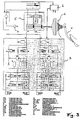
- Fig. 3 shows a known brake system, such as that on page 212 of the document already mentioned ATZ ", 1997, is partially shown.
- a brake pedal 1 with a brake booster 2 a brake booster 2 with a master brake cylinder 5 and a master brake cylinder 5 with an electronically controllable brake unit, here a hydraulic unit, are connected
- the form of a hydraulic unit 3 the brake pressure in the wheel brakes HL, HR, VL and VR can be set independently of the pre-pressure prevailing at the output of the master brake cylinder 5.
- the pre-pressure (Pvor) prevailing at the output of the master brake cylinder 5 is assigned to the brake system by means of a pre-pressure sensor 4 electronic control unit 6.
- This form is a pedal actuation quantity that is directly proportional to the pedal force F applied by the driver via the brake pedal.
- the electronic control unit 6 has further inputs and outputs for others Input and output signals on; in particular, control lines from Control unit 6 is provided for controlling the actuators of the brake unit 3.
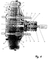
- Fig. 1 is a possible embodiment of the brake booster shown in Fig. 3 2 shown.
- Known brake boosters have, for example the following components:
- a spring 1 a reaction piston 2, a sealing bellows 3, a housing base 4, a membrane plate 5, a housing cover 6, a membrane 7, a valve housing 8, a reaction disk 9, a tension bolt 10, a Sensing piston 11, a control valve 12, an actuating rod 13, an air filter 14, a draw bolt 15, a bolt 16, a feeler 17 and one Vacuum connection 18.
- the expansion of a known brake booster is essential to the invention 2 (FIG. 3) of the vacuum type according to FIG. 1 around a differential pressure sensor 20 between the vacuum chamber 21 of the brake booster and the atmosphere and a differential pressure sensor 19 between the Vacuum chamber 21 and the working chamber 22 of the brake booster.
- the pressure sensors 19 and 20 can only be designed as switches be, the first switching state in the presence of a differential pressure and whose second switching state is set in the absence of a differential pressure become.
- the signals from the differential pressure sensors 19 and 20 are from the control unit 6 recorded and evaluated. Is by means of the differential pressure sensor 20 (Fig. 1) recognized that between the pressure in the vacuum chamber 21 and the atmospheric pressure there is no difference and is measured using the pre-pressure sensor 4 (Fig. 3) recognized that the pressure at the output of the master cylinder 5th rises or has exceeded a predetermined threshold, that excludes Control unit 6 from the failure of the brake booster. In this Case there is no vacuum in the brake booster.
- the control unit 6 concludes that the Brake booster when detected by the differential pressure sensor 19 is that the pressure in the working chamber 22 is at most equal to the pressure in the vacuum chamber 21, and if at the same time by means of the pre-pressure sensor 4 (Fig. 3) is recognized that the pressure at the output of the master cylinder 5 rises or has exceeded a predetermined threshold. Is by means of the differential pressure sensor 19 clearly measurable that the pressure in the Working chamber 22 is less than the pressure in the vacuum chamber 21 or that the vacuum in the working chamber 22 is greater than the vacuum in the vacuum chamber 21 is already on the failure of the Breskraftkraftkraftver are closed before by means of the pre-pressure sensor 4 (Fig. 3) it is recognized that the pressure at the output of the master cylinder 5 increases or has exceeded a predetermined threshold. In these cases the suction of atmospheric air in the working chamber 22 hindered.
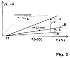
- the brake pressure p generated in the wheel brakes HL, HR, VL and VR in such a way that a predetermined Minimum target deceleration curve B or C (Fig. 2) depending of the pedal force F or a pedal actuation quantity proportional to it results.
- the thin deceleration curve A represents a normal deceleration curve with the brake booster intact, the gradient of which decreases at the modulation point.
- the gradient of the deceleration curve A after the modulation point corresponds to the gradient of the deceleration curve D, which would only be achieved if the brake booster failed.
- the approval requirement for a type test is stipulated that if the brake booster fails with a foot force of 500 N, a deceleration -a of 2.9 m / s 2 must be achieved, then in a case 1.
- the deceleration curve B becomes the minimum target -Delay history given.
- a minimum target deceleration curve C can also be specified in a case 2, which leads to a greater delay compared to the admission requirements. Due to the deceleration curve C, however, the characteristic of the braking behavior should still deviate from that of a braking behavior with an intact brake booster in order to make the driver aware of an anomaly.
- the brake pressure p is generated in the wheel brakes in such a way that depending on from the pedal force F the minimum target deceleration curve B or C results.
Landscapes
- Engineering & Computer Science (AREA)
- Transportation (AREA)
- Mechanical Engineering (AREA)
- Physics & Mathematics (AREA)
- Fluid Mechanics (AREA)
- Valves And Accessory Devices For Braking Systems (AREA)
- Regulating Braking Force (AREA)
- Braking Systems And Boosters (AREA)
Abstract
- wenn zwischen dem Druck in der Vakuumkammer (21) und dem Atmosphärendruck keine Differenz gemessen wird, der Druck am Ausgang des Hauptbremszylinders (5) jedoch ansteigt oder eine vorgegebene Schwelle überschreitet oder
- wenn der Druck in der Arbeitskammer (22) höchstens gleich dem Druck in der Vakuumkammer (21) ist, der Druck am Ausgang des Hauptbremszylinders (5) jedoch ansteigt oder eine vorgegebene Schwelle überschreitet.
Description
- Fig. 1
- einen Bremskraftverstärker, der zur Erkennung des Ausfalls des Bremskraftverstärkers mit Differenzdrucksensoren versehen ist,
- Fig. 2
- Beispiele für einen Mindest-Soll-Verzögerungsverlauf und
- Fig. 3
- eine mögliche bekannte Bremsanlage, durch die die Erfindung realisiert werden kann.
Claims (3)
- Bremsanlage für Kraftfahrzeuge mit einem Bremspedal, mit einem Bremskraftverstärker, mit einem Hauptbremszylinder und mit einer elektronisch regelbaren Bremseinheit, die zwischen dem Hauptbremszylinder und den Radbremsen angeordnet ist und durch die mittels eines elektronischen Steuergeräts der Bremsdruck in den Radbremsen unabhängig von dem am Ausgang des Hauptbremszylinders herrschenden Vordruck einstellbar ist, dadurch gekennzeichnet, daß bei Ausfall des Bremskraftverstärkers (2) mittels des elektronischen Steuergeräts (6) und mittels der elektronisch regelbaren Bremseinheit (3) der Bremsdruck (p) in den Radbremsen (HL, HR, VL, VR) derart erzeugt wird, daß sich ein vorgegebener Mindest-Soll-Verzögerungsverlauf (B; C) in Abhängigkeit von einer Pedalbetätigungsgröße (F), die direkt proportional zu der durch den Fahrer über das Bremspedal (1) aufgebrachten Pedalkraft ist, ergibt.
- Bremsanlage nach Patentanspruch 1, dadurch gekennzeichnet, daß der Ausfall des lBremskraftverstärkers (2) erkannt wird, wenn zwischen dem Druck in der Vakuumkammer (21) und dem Atmosphärendruck keine Differenz gemessen wird, der Druck am Ausgang des Hauptbremszylinders (5) jedoch ansteigt oder eine vorgegebene Schwelle überschreitet.
- Bremsanlage nach Patentanspruch 1 oder 2, dadurch gekennzeichnet, daß der Ausfall des Bremskraftverstärkers (2) erkannt wird, wenn der Druck in der Arbeitskammer (22) höchstens gleich dem Druck in der Vakuumkammer (21) ist, der Druck am Ausgang des Hauptbremszylinders (5) jedoch ansteigt oder eine vorgegebene Schwelle überschreitet.
Applications Claiming Priority (2)
| Application Number | Priority Date | Filing Date | Title |
|---|---|---|---|
| DE19743959 | 1997-10-04 | ||
| DE19743959A DE19743959A1 (de) | 1997-10-04 | 1997-10-04 | Bremsanlage für Kraftfahrzeuge |
Publications (2)
| Publication Number | Publication Date |
|---|---|
| EP0906858A1 true EP0906858A1 (de) | 1999-04-07 |
| EP0906858B1 EP0906858B1 (de) | 2003-11-26 |
Family
ID=7844643
Family Applications (1)
| Application Number | Title | Priority Date | Filing Date |
|---|---|---|---|
| EP98116488A Expired - Lifetime EP0906858B1 (de) | 1997-10-04 | 1998-09-01 | Bremsanlage für Kraftfahrzeuge |
Country Status (5)
| Country | Link |
|---|---|
| US (1) | US6062656A (de) |
| EP (1) | EP0906858B1 (de) |
| JP (1) | JP4185597B2 (de) |
| DE (2) | DE19743959A1 (de) |
| ES (1) | ES2212182T3 (de) |
Cited By (3)
| Publication number | Priority date | Publication date | Assignee | Title |
|---|---|---|---|---|
| FR2792898A1 (fr) * | 1999-04-28 | 2000-11-03 | Bosch Braking Sys Corp | Systeme de freins |
| EP1145927A1 (de) * | 2000-04-12 | 2001-10-17 | Bayerische Motoren Werke Aktiengesellschaft | Elektrisch gesteuertes, insbesondere elektromechanisches Bremssystem für ein Kraftfahrzeug |
| WO2007020249A1 (de) * | 2005-08-15 | 2007-02-22 | Continental Teves Ag & Co. Ohg | Verfahren und vorrichtung zum betrieb einer hydraulischen fahrzeugbremsanlage |
Families Citing this family (25)
| Publication number | Priority date | Publication date | Assignee | Title |
|---|---|---|---|---|
| DE19743960A1 (de) * | 1997-10-04 | 1999-04-08 | Bayerische Motoren Werke Ag | Bremsanlage für Kraftfahrzeuge |
| JP3458773B2 (ja) * | 1998-08-24 | 2003-10-20 | トヨタ自動車株式会社 | ブースタ異常判定装置 |
| DE19925794B4 (de) * | 1999-06-05 | 2013-04-04 | Robert Bosch Gmbh | Bremsdruck-Steuereinrichtung und Verfahren zur Aktivierung und Deaktivierung einer hydraulischen Bremskraftverstärkung |
| DE19935899B4 (de) * | 1999-07-30 | 2010-12-02 | Robert Bosch Gmbh | Verfahren zum sicheren Betreiben eines Bremskraftverstärkersystems, Bremskraftverstärkersystem und Diagnosevorrichtung dafür zur Ausführung des Verfahrens |
| US6871918B2 (en) | 1999-07-30 | 2005-03-29 | Robert Bosch Gmbh | Method for the reliable operation of a brake booster system, brake booster system, and circuit therefor for implementing the method |
| JP4329205B2 (ja) * | 1999-09-10 | 2009-09-09 | トヨタ自動車株式会社 | 液圧ブレーキシステムの加圧装置異常検出装置 |
| US6493617B1 (en) * | 2000-01-07 | 2002-12-10 | Ford Global Technologies, Inc. | Lean burn engine with brake system |
| US6557403B1 (en) * | 2000-01-07 | 2003-05-06 | Ford Global Technologies, Inc. | Lean engine with brake system |
| US6880532B1 (en) * | 2000-01-07 | 2005-04-19 | Ford Global Technologies, Llc | Engine operation parameter estimation method |
| WO2002014131A1 (de) * | 2000-08-11 | 2002-02-21 | Continental Teves Ag & Co. Ohg | Verfahren zur steuerung einer elektronisch regelbaren bremsanlage und schaltungsanordung |
| FR2813840B1 (fr) * | 2000-09-13 | 2003-04-04 | Bosch Gmbh Robert | Servofrein |
| DE50209980D1 (de) * | 2001-06-02 | 2007-05-31 | Continental Teves Ag & Co Ohg | Unterdruckbremskraftverstärker einer fahrzeugbremsanlage |
| DE10210603A1 (de) * | 2002-03-11 | 2003-10-02 | Continental Teves Ag & Co Ohg | Verfahren und Vorrichtung zur Steuerung einer Fahrzeugbremsanlage mit aktiver hyraulischer Bremskraftverstärkung |
| DE50308276D1 (de) * | 2003-01-09 | 2007-11-08 | Ford Global Tech Llc | Regelung einer Brennkraftmaschine mit Bremskraftverstärker |
| US7686404B2 (en) * | 2005-02-23 | 2010-03-30 | Continental Teves, Inc. | Electro-hydraulic braking system |
| US7878053B2 (en) * | 2006-12-22 | 2011-02-01 | Gm Global Technology Operations, Inc. | Engine off brake booster leak diagnostic systems and methods |
| US8899033B2 (en) | 2007-09-19 | 2014-12-02 | GM Global Technology Operations LLC | Brake booster leak detection system |
| DE102008011606A1 (de) * | 2008-02-28 | 2009-09-03 | Robert Bosch Gmbh | Vorrichtung und Verfahren zum Erkennen einer Bremsbetätigung |
| JP5061051B2 (ja) * | 2008-07-11 | 2012-10-31 | 日立オートモティブシステムズ株式会社 | ブレーキ制御装置 |
| DE102011088938A1 (de) * | 2011-01-24 | 2012-07-26 | Continental Teves Ag & Co. Ohg | Verfahren zur Überwachung des Signalwertes eines Unterdrucksensors |
| JP6067238B2 (ja) * | 2011-04-05 | 2017-01-25 | ロベルト・ボッシュ・ゲゼルシャフト・ミト・ベシュレンクテル・ハフツングRobert Bosch Gmbh | 油圧式ブースト補償システムのための車両の真空センサにおけるエラー状態の高速検出 |
| DE102012207553A1 (de) * | 2011-05-06 | 2012-11-08 | Continental Teves Ag & Co. Ohg | Verfahren zur Plausibilisierung eines Vakuumsensors |
| DE102011084781A1 (de) * | 2011-10-19 | 2013-04-25 | Bayerische Motoren Werke Aktiengesellschaft | Verfahren zum Sicherstellen der Bremswirkung von in einem Fahrzeug angebrachten Bremsaktuatoren |
| DE102013208671A1 (de) * | 2013-05-13 | 2014-11-13 | Robert Bosch Gmbh | Steuervorrichtung für zumindest eine elektrische Parkbremse eines Bremssystems eines Fahrzeugs und Verfahren zum Betreiben eines Bremssystems eines Fahrzeugs mit einem Bremskraftverstärker und einer elektrischen Parkbremse |
| CN115352426B (zh) * | 2022-09-14 | 2023-09-05 | 东风汽车集团股份有限公司 | 一种基于线控制动的失效保护方法和系统 |
Citations (2)
| Publication number | Priority date | Publication date | Assignee | Title |
|---|---|---|---|---|
| US3685289A (en) * | 1969-08-10 | 1972-08-22 | Uichiro Kobashi | Method for control of a power brake and apparatus embodying said method |
| DE3606136A1 (de) * | 1985-05-07 | 1986-11-13 | FAG Kugelfischer Georg Schäfer KGaA, 8720 Schweinfurt | Hilfskraftverstaerkte brems- oder kupplungsanlage |
Family Cites Families (4)
| Publication number | Priority date | Publication date | Assignee | Title |
|---|---|---|---|---|
| DE19525985A1 (de) * | 1995-07-17 | 1997-01-23 | Bayerische Motoren Werke Ag | Bremsanlage für Kraftfahrzeuge mit einem Bremskraftverstärker |
| DE19542654A1 (de) * | 1995-11-15 | 1997-05-22 | Lucas Ind Plc | Elektronische steuerbare Bremsanlage für Kraftfahrzeuge |
| DE69602002T2 (de) * | 1996-04-03 | 1999-09-30 | Lucas Industries P.L.C., Solihull | Elektronisch gesteuerter Bremskraftverstärker |
| EP0850815B1 (de) * | 1996-12-27 | 2002-10-09 | Denso Corporation | Kraftfahrzeugbremssystem |
-
1997
- 1997-10-04 DE DE19743959A patent/DE19743959A1/de not_active Withdrawn
-
1998
- 1998-09-01 DE DE59810249T patent/DE59810249D1/de not_active Expired - Lifetime
- 1998-09-01 ES ES98116488T patent/ES2212182T3/es not_active Expired - Lifetime
- 1998-09-01 EP EP98116488A patent/EP0906858B1/de not_active Expired - Lifetime
- 1998-10-01 JP JP28002198A patent/JP4185597B2/ja not_active Expired - Fee Related
- 1998-10-05 US US09/166,151 patent/US6062656A/en not_active Expired - Lifetime
Patent Citations (2)
| Publication number | Priority date | Publication date | Assignee | Title |
|---|---|---|---|---|
| US3685289A (en) * | 1969-08-10 | 1972-08-22 | Uichiro Kobashi | Method for control of a power brake and apparatus embodying said method |
| DE3606136A1 (de) * | 1985-05-07 | 1986-11-13 | FAG Kugelfischer Georg Schäfer KGaA, 8720 Schweinfurt | Hilfskraftverstaerkte brems- oder kupplungsanlage |
Cited By (3)
| Publication number | Priority date | Publication date | Assignee | Title |
|---|---|---|---|---|
| FR2792898A1 (fr) * | 1999-04-28 | 2000-11-03 | Bosch Braking Sys Corp | Systeme de freins |
| EP1145927A1 (de) * | 2000-04-12 | 2001-10-17 | Bayerische Motoren Werke Aktiengesellschaft | Elektrisch gesteuertes, insbesondere elektromechanisches Bremssystem für ein Kraftfahrzeug |
| WO2007020249A1 (de) * | 2005-08-15 | 2007-02-22 | Continental Teves Ag & Co. Ohg | Verfahren und vorrichtung zum betrieb einer hydraulischen fahrzeugbremsanlage |
Also Published As
| Publication number | Publication date |
|---|---|
| JPH11157428A (ja) | 1999-06-15 |
| ES2212182T3 (es) | 2004-07-16 |
| DE59810249D1 (de) | 2004-01-08 |
| JP4185597B2 (ja) | 2008-11-26 |
| DE19743959A1 (de) | 1999-04-08 |
| US6062656A (en) | 2000-05-16 |
| EP0906858B1 (de) | 2003-11-26 |
Similar Documents
| Publication | Publication Date | Title |
|---|---|---|
| EP0906858B1 (de) | Bremsanlage für Kraftfahrzeuge | |
| EP1000830B1 (de) | Bremswertgeber mit integrierter Additionsredundanz | |
| EP2059428B1 (de) | Pneumatische fahrzeugbremsanlage sowie verfahren zum steuern einer derartigen bremsanlage | |
| EP0616932B1 (de) | Bremskraftverstärkersystem zum Regeln eines Bremsdruckes mit einem Bremskraftverstärker | |
| DE19620540C1 (de) | Elektronisch steuerbare Bremsanlage | |
| EP0187901A2 (de) | Elektrisch gesteuerte Bremsanlage für Fahrzeuge | |
| DE19750977B4 (de) | Bremsanlage | |
| EP0906859A1 (de) | Bremsanlage für Kraftfahrzeuge | |
| WO1994022699A1 (de) | Hydraulische bremsanlage mit schlupfregelung | |
| EP0418495A1 (de) | Einrichtung zur Reifendrucküberwachung | |
| DE102017003782A1 (de) | Verfahren zum Überwachen einer Umsetzung einer automatisiert angeforderten Bremsvorgabe sowie Bremssystem | |
| DE102011085986A1 (de) | Bremsanlage | |
| DE10039670A1 (de) | Pedalsimulationsvorrichtung | |
| DE102008020934A1 (de) | Hauptbremszylinderanordnung mit Betätigungserfassung für eine Kraftfahrzeugbremsanlage und Kraftfahrzeugbremsanlage | |
| DE19925794B4 (de) | Bremsdruck-Steuereinrichtung und Verfahren zur Aktivierung und Deaktivierung einer hydraulischen Bremskraftverstärkung | |
| DE102015006396A1 (de) | Elektrohydraulische Bremskrafterzeugungsvorrichtung für eine elektrohydraulische Kraftfahrzeug-Bremsanlage | |
| EP1051316B1 (de) | Bremskraftübersetzungsvorrichtung, insbesondere für kraftfahrzeuge | |
| EP2257451B1 (de) | Verfahren zum erkennen von veränderungen in der steifigkeit eines hydraulischen bremssystems | |
| EP3585666B1 (de) | Verfahren zur diagnose eines bremssystems eines kraftfahrzeugs sowie entsprechendes bremssystem | |
| WO2019206565A1 (de) | Steuerventil, elektronisch steuerbares bremssystem sowie verfahren zum steuern des elektronisch steuerbaren bremssystems | |
| DE10118635A1 (de) | Verfahren zum Betreiben eines Bremsassistent-System | |
| DE3114431C2 (de) | Steuervorrichtung für eine in ihrer Bremsleistung veränderbare Dauerbremse | |
| WO2006061279A1 (de) | Druckmittelbetätigbare fahrzeugbremsanlage und verfahren zur ansteuerung einer druckmittelbetätigbaren fahrzeugbremsanlage | |
| DE102004013868B4 (de) | Pedalvorrichtung zum Betätigen einer Bremsanlage eines Kraftfahrzeugs und entsprechendes Verfahren zum Überprüfen eines Pedalkraftsensors | |
| EP0360013A1 (de) | Blockiergeschützte Kraftfahrzeugbremsanlage |
Legal Events
| Date | Code | Title | Description |
|---|---|---|---|
| PUAI | Public reference made under article 153(3) epc to a published international application that has entered the european phase |
Free format text: ORIGINAL CODE: 0009012 |
|
| AK | Designated contracting states |
Kind code of ref document: A1 Designated state(s): DE ES FR GB IT SE |
|
| AX | Request for extension of the european patent |
Free format text: AL;LT;LV;MK;RO;SI |
|
| 17P | Request for examination filed |
Effective date: 19990901 |
|
| AKX | Designation fees paid |
Free format text: DE ES FR GB IT SE |
|
| 17Q | First examination report despatched |
Effective date: 20010702 |
|
| GRAH | Despatch of communication of intention to grant a patent |
Free format text: ORIGINAL CODE: EPIDOS IGRA |
|
| GRAS | Grant fee paid |
Free format text: ORIGINAL CODE: EPIDOSNIGR3 |
|
| GRAA | (expected) grant |
Free format text: ORIGINAL CODE: 0009210 |
|
| AK | Designated contracting states |
Kind code of ref document: B1 Designated state(s): DE ES FR GB IT SE |
|
| REG | Reference to a national code |
Ref country code: GB Ref legal event code: FG4D Free format text: NOT ENGLISH |
|
| GBT | Gb: translation of ep patent filed (gb section 77(6)(a)/1977) |
Effective date: 20031128 |
|
| REF | Corresponds to: |
Ref document number: 59810249 Country of ref document: DE Date of ref document: 20040108 Kind code of ref document: P |
|
| REG | Reference to a national code |
Ref country code: SE Ref legal event code: TRGR |
|
| ET | Fr: translation filed | ||
| REG | Reference to a national code |
Ref country code: ES Ref legal event code: FG2A Ref document number: 2212182 Country of ref document: ES Kind code of ref document: T3 |
|
| PLBE | No opposition filed within time limit |
Free format text: ORIGINAL CODE: 0009261 |
|
| STAA | Information on the status of an ep patent application or granted ep patent |
Free format text: STATUS: NO OPPOSITION FILED WITHIN TIME LIMIT |
|
| 26N | No opposition filed |
Effective date: 20040827 |
|
| REG | Reference to a national code |
Ref country code: FR Ref legal event code: PLFP Year of fee payment: 18 |
|
| PGFP | Annual fee paid to national office [announced via postgrant information from national office to epo] |
Ref country code: ES Payment date: 20150820 Year of fee payment: 18 Ref country code: GB Payment date: 20150924 Year of fee payment: 18 |
|
| PGFP | Annual fee paid to national office [announced via postgrant information from national office to epo] |
Ref country code: FR Payment date: 20150928 Year of fee payment: 18 Ref country code: SE Payment date: 20150911 Year of fee payment: 18 |
|
| PGFP | Annual fee paid to national office [announced via postgrant information from national office to epo] |
Ref country code: IT Payment date: 20150924 Year of fee payment: 18 |
|
| PGFP | Annual fee paid to national office [announced via postgrant information from national office to epo] |
Ref country code: DE Payment date: 20150919 Year of fee payment: 18 |
|
| REG | Reference to a national code |
Ref country code: DE Ref legal event code: R119 Ref document number: 59810249 Country of ref document: DE |
|
| PG25 | Lapsed in a contracting state [announced via postgrant information from national office to epo] |
Ref country code: SE Free format text: LAPSE BECAUSE OF NON-PAYMENT OF DUE FEES Effective date: 20160902 |
|
| REG | Reference to a national code |
Ref country code: SE Ref legal event code: EUG |
|
| GBPC | Gb: european patent ceased through non-payment of renewal fee |
Effective date: 20160901 |
|
| REG | Reference to a national code |
Ref country code: FR Ref legal event code: ST Effective date: 20170531 |
|
| PG25 | Lapsed in a contracting state [announced via postgrant information from national office to epo] |
Ref country code: FR Free format text: LAPSE BECAUSE OF NON-PAYMENT OF DUE FEES Effective date: 20160930 Ref country code: DE Free format text: LAPSE BECAUSE OF NON-PAYMENT OF DUE FEES Effective date: 20170401 Ref country code: GB Free format text: LAPSE BECAUSE OF NON-PAYMENT OF DUE FEES Effective date: 20160901 |
|
| PG25 | Lapsed in a contracting state [announced via postgrant information from national office to epo] |
Ref country code: IT Free format text: LAPSE BECAUSE OF NON-PAYMENT OF DUE FEES Effective date: 20160901 |
|
| PG25 | Lapsed in a contracting state [announced via postgrant information from national office to epo] |
Ref country code: ES Free format text: LAPSE BECAUSE OF NON-PAYMENT OF DUE FEES Effective date: 20160902 |
|
| REG | Reference to a national code |
Ref country code: ES Ref legal event code: FD2A Effective date: 20181116 |