EP0906823A1 - Verstellbare Blasfolienführung - Google Patents
Verstellbare Blasfolienführung Download PDFInfo
- Publication number
- EP0906823A1 EP0906823A1 EP98116793A EP98116793A EP0906823A1 EP 0906823 A1 EP0906823 A1 EP 0906823A1 EP 98116793 A EP98116793 A EP 98116793A EP 98116793 A EP98116793 A EP 98116793A EP 0906823 A1 EP0906823 A1 EP 0906823A1
- Authority
- EP
- European Patent Office
- Prior art keywords
- frame
- rods
- pivot means
- bubble
- guide unit
- Prior art date
- Legal status (The legal status is an assumption and is not a legal conclusion. Google has not performed a legal analysis and makes no representation as to the accuracy of the status listed.)
- Granted
Links
- 238000001125 extrusion Methods 0.000 description 3
- 238000000034 method Methods 0.000 description 3
- 238000010276 construction Methods 0.000 description 2
- 239000004033 plastic Substances 0.000 description 2
- 229920003023 plastic Polymers 0.000 description 2
- 239000007787 solid Substances 0.000 description 2
- CWYNVVGOOAEACU-UHFFFAOYSA-N Fe2+ Chemical compound [Fe+2] CWYNVVGOOAEACU-UHFFFAOYSA-N 0.000 description 1
- 239000004809 Teflon Substances 0.000 description 1
- 229920006362 Teflon® Polymers 0.000 description 1
- 239000003795 chemical substances by application Substances 0.000 description 1
- 230000013011 mating Effects 0.000 description 1
- 239000002184 metal Substances 0.000 description 1
- 230000010355 oscillation Effects 0.000 description 1
- 229920000642 polymer Polymers 0.000 description 1
Images

Classifications
-
- B—PERFORMING OPERATIONS; TRANSPORTING
- B29—WORKING OF PLASTICS; WORKING OF SUBSTANCES IN A PLASTIC STATE IN GENERAL
- B29C—SHAPING OR JOINING OF PLASTICS; SHAPING OF MATERIAL IN A PLASTIC STATE, NOT OTHERWISE PROVIDED FOR; AFTER-TREATMENT OF THE SHAPED PRODUCTS, e.g. REPAIRING
- B29C48/00—Extrusion moulding, i.e. expressing the moulding material through a die or nozzle which imparts the desired form; Apparatus therefor
- B29C48/25—Component parts, details or accessories; Auxiliary operations
- B29C48/88—Thermal treatment of the stream of extruded material, e.g. cooling
- B29C48/90—Thermal treatment of the stream of extruded material, e.g. cooling with calibration or sizing, i.e. combined with fixing or setting of the final dimensions of the extruded article
- B29C48/907—Thermal treatment of the stream of extruded material, e.g. cooling with calibration or sizing, i.e. combined with fixing or setting of the final dimensions of the extruded article using adjustable calibrators, e.g. the dimensions of the calibrator being changeable
-
- B—PERFORMING OPERATIONS; TRANSPORTING
- B29—WORKING OF PLASTICS; WORKING OF SUBSTANCES IN A PLASTIC STATE IN GENERAL
- B29C—SHAPING OR JOINING OF PLASTICS; SHAPING OF MATERIAL IN A PLASTIC STATE, NOT OTHERWISE PROVIDED FOR; AFTER-TREATMENT OF THE SHAPED PRODUCTS, e.g. REPAIRING
- B29C48/00—Extrusion moulding, i.e. expressing the moulding material through a die or nozzle which imparts the desired form; Apparatus therefor
- B29C48/03—Extrusion moulding, i.e. expressing the moulding material through a die or nozzle which imparts the desired form; Apparatus therefor characterised by the shape of the extruded material at extrusion
- B29C48/09—Articles with cross-sections having partially or fully enclosed cavities, e.g. pipes or channels
- B29C48/10—Articles with cross-sections having partially or fully enclosed cavities, e.g. pipes or channels flexible, e.g. blown foils
-
- B—PERFORMING OPERATIONS; TRANSPORTING
- B29—WORKING OF PLASTICS; WORKING OF SUBSTANCES IN A PLASTIC STATE IN GENERAL
- B29C—SHAPING OR JOINING OF PLASTICS; SHAPING OF MATERIAL IN A PLASTIC STATE, NOT OTHERWISE PROVIDED FOR; AFTER-TREATMENT OF THE SHAPED PRODUCTS, e.g. REPAIRING
- B29C48/00—Extrusion moulding, i.e. expressing the moulding material through a die or nozzle which imparts the desired form; Apparatus therefor
- B29C48/25—Component parts, details or accessories; Auxiliary operations
- B29C48/355—Conveyors for extruded articles
-
- B—PERFORMING OPERATIONS; TRANSPORTING
- B29—WORKING OF PLASTICS; WORKING OF SUBSTANCES IN A PLASTIC STATE IN GENERAL
- B29C—SHAPING OR JOINING OF PLASTICS; SHAPING OF MATERIAL IN A PLASTIC STATE, NOT OTHERWISE PROVIDED FOR; AFTER-TREATMENT OF THE SHAPED PRODUCTS, e.g. REPAIRING
- B29C48/00—Extrusion moulding, i.e. expressing the moulding material through a die or nozzle which imparts the desired form; Apparatus therefor
- B29C48/25—Component parts, details or accessories; Auxiliary operations
- B29C48/88—Thermal treatment of the stream of extruded material, e.g. cooling
- B29C48/90—Thermal treatment of the stream of extruded material, e.g. cooling with calibration or sizing, i.e. combined with fixing or setting of the final dimensions of the extruded article
- B29C48/901—Thermal treatment of the stream of extruded material, e.g. cooling with calibration or sizing, i.e. combined with fixing or setting of the final dimensions of the extruded article of hollow bodies
- B29C48/903—Thermal treatment of the stream of extruded material, e.g. cooling with calibration or sizing, i.e. combined with fixing or setting of the final dimensions of the extruded article of hollow bodies externally
Definitions
- the present invention relates to the plastics industry in general and in particular to apparatus for extruding blown film. More particularly, it relates to post extrusion devices generally known as bubble cages or guides.
- All blown film is extruded either vertically, up or down, or horizontally.
- the polymer once the polymer exits the cylindrical die, it forms a cylindrical "bubble" and is drawn from the die by means of two rollers (usually known as “nip rollers") which contact a collapsed outer end of the bubble.
- the distance between the die surface and the nip rollers may vary from six to over one hundred feet.
- the bubble As it exits the die, the bubble is inflated with air to the desired diameter. Normally, the air inflates the bubble through the die and once the requisite diameter has been reached inflation ceases and the air is trapped between the face of the die and the nip roller.
- the bubble must be guided to ensure good centering and tracking with minimum side-to-side oscillation or off-centre movement.
- the guiding has been accomplished by means of bubble cages; individual guiding bars; guiding bars interconnected by means of chains, gears and the like; and a variety of other methods.
- the present invention provides a simple, adjustable bubble guide or cage (hereafter guide).
- a bubble guide unit comprises two concentric frames, at least one of which rotates relative to the other, through which the film bubble passes.
- At least four bubble guiding rods are arranged symmetrically about the center of rotation to pivotally engage one frame at one end and to have its other end portion freely engage the other frame.
- Freely engage here means that the other end of each rod is free to pivot to some extent as well as to move in the direction of its length beyond the pivoting point and back. This is most easily accomplished by a pivoting ring through which the rod passes or, less elegantly by a fixed ring having an aperture larger than the rod diameter.
- a bubble guide unit in accordance with the invention comprises:
- the primary pivot means are located at corners of a first square, and the secondary pivot means are located at the corners of a second square.
- the first and second frames are preferably in the form of concentric rings.
- Such bubble guide units may be stacked vertically or horizontally and their rotating frames interconnected to allow for a single adjustment mechanism.
- posts connecting corresponding parts of the frames will provide the pivot means holding the rods.
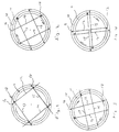
- the bubble guide unit comprises two concentric ring-frames, i.e. a stationary outer frame 10 and an inner frame 11 rotatable about its center.
- Four guide rods are shown diagrammatically as lines 12, 13, 14 and 15.
- the rod 12 is attached at one end to a primary pivot 16 anchored to the outer ring 10, while its other end portion is slidably attached, near its end, to a secondary pivot 17 anchored to the inner ring 11.
- the other rods 13, 14 and 15 are similarly attached at one end to a primary pivot on the outer frame and slidably attached near the other end to a secondary pivot on the inner frame.
- the rods 12, 13, 14 and 15 must be of sufficient length so as not retract out of the pivot 17 when the inner frame 11 is rotated to the condition of Figure 4 where the opening between the rods is at a minimum size.
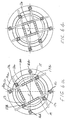
- the bubble guide is constructed with two lower and two upper frames in the form of outer and inner lower rings 10a, 11a, and outer and inner upper rings 10b, 11b, with a hole in the centre of the each inner ring.
- the outer rings 10a and 10b are connected by four equally spaced outer vertical posts 16a, 16b, 16c, 16d, and the inner rings 11a, 11b are connected by four equally spaced inner vertical posts 17a, 17b, 17c, 17d.
- the lower outer and inner rings 10a and 11a act like inner and outer portions of a bearing, where the outer ring remains stationary, the inner ring being the race of the bearing that is able to rotate.
- the outer ring 10a holds the posts 16a, etc.
- the lower rings and the upper rings are a mirror image of each other.
- the outer posts 16a, etc. have been drilled adjacent their lower and upper ends so that each post accepts round rods 12, 13, 14, and 15, that have been fixed with a setscrew, adjacent their lower and upper ends.
- the rods are arranged in groups of lower and upper rods adjacent to the lower and upper rings respectively, and the distances of the rods from the rings are staggered vertically so that there is no interference between rods.
- the rods may have a covering, and this may be in the form of rollers, either in the form of a single solid roller for each rod, or a series of small rollers, as shown at 20 in Figs.6a and 6b, that would rotate on the rods by way of friction with the bubble if enough friction were present.
- rods as used herein means also rods with any covering used to assist in guiding the blown film, whether it is solid or segmented rollers, ferrous or nonferrous metal, plastic covering such as Teflon (TM) or an applied slippery agent. It is also possible to have hollow tubes (or tube-like shape) with a series of holes or slots through which air passes to reduce friction or contact with the blown film.
- any covering used to assist in guiding the blown film whether it is solid or segmented rollers, ferrous or nonferrous metal, plastic covering such as Teflon (TM) or an applied slippery agent.
- TM Teflon
Landscapes
- Engineering & Computer Science (AREA)
- Mechanical Engineering (AREA)
- Physics & Mathematics (AREA)
- Thermal Sciences (AREA)
- Shaping By String And By Release Of Stress In Plastics And The Like (AREA)
- Transmission Devices (AREA)
Applications Claiming Priority (5)
| Application Number | Priority Date | Filing Date | Title |
|---|---|---|---|
| CA002216177A CA2216177A1 (en) | 1997-09-23 | 1997-09-23 | Adjustable bubble guide or cage |
| CA2216177 | 1997-09-23 | ||
| CA2229821 | 1998-02-18 | ||
| CA002229821A CA2229821C (en) | 1997-09-23 | 1998-02-18 | Adjustable bubble guide or cage |
| US09/032,582 US6059554A (en) | 1997-09-23 | 1998-02-27 | Adjustable bubble guide or cage |
Publications (2)
| Publication Number | Publication Date |
|---|---|
| EP0906823A1 true EP0906823A1 (de) | 1999-04-07 |
| EP0906823B1 EP0906823B1 (de) | 2003-01-15 |
Family
ID=27170459
Family Applications (1)
| Application Number | Title | Priority Date | Filing Date |
|---|---|---|---|
| EP98116793A Expired - Lifetime EP0906823B1 (de) | 1997-09-23 | 1998-09-05 | Verstellbare Blasfolienführung |
Country Status (3)
| Country | Link |
|---|---|
| US (1) | US6059554A (de) |
| EP (1) | EP0906823B1 (de) |
| CA (1) | CA2229821C (de) |
Cited By (3)
| Publication number | Priority date | Publication date | Assignee | Title |
|---|---|---|---|---|
| EP1386719A1 (de) * | 2002-08-01 | 2004-02-04 | Reifenhäuser GmbH & Co. Maschinenfabrik | Vorrichtung zur Herstellung von Kunststofffolien |
| CN102152476A (zh) * | 2011-03-07 | 2011-08-17 | 聊城华塑工业有限公司 | 软轴联动稳泡装置 |
| ITCO20100051A1 (it) * | 2010-09-07 | 2012-03-08 | Decatex Srl | Guida a movimento ortogonale per film plastici in bolla |
Families Citing this family (3)
| Publication number | Priority date | Publication date | Assignee | Title |
|---|---|---|---|---|
| US6679025B1 (en) * | 2000-12-08 | 2004-01-20 | Process Marketing, Inc. | Modular tower |
| CA2355140A1 (en) * | 2001-08-16 | 2003-02-16 | Robert D. Krycki | Motorized air ring |
| CN115519876B (zh) * | 2022-10-19 | 2024-04-16 | 安徽紫江喷铝环保材料有限公司 | 一种复合机点气泡装置 |
Citations (5)
| Publication number | Priority date | Publication date | Assignee | Title |
|---|---|---|---|---|
| US3980418A (en) * | 1975-09-05 | 1976-09-14 | Gloucester Engineering Co. Inc. | Guide assembly for air-expanded thermoplastic tubes |
| US4355966A (en) * | 1981-05-04 | 1982-10-26 | E. B. Westlake, Jr. | Automatic control of bubble size in blown film |
| JPS5857924A (ja) * | 1981-10-02 | 1983-04-06 | Modern Mach Kk | インフレ−シヨンフイルム成形装置におけるバプル冷却用のエア−リング |
| DE3610488A1 (de) * | 1985-04-03 | 1986-10-16 | Tomy Machinery Mfg. Co., Ltd., Tokio/Tokyo | Verfahren und vorrichtung zur herstellung von blasfolien |
| WO1992016350A1 (en) * | 1991-03-21 | 1992-10-01 | Minnesota Mining And Manufacturing Company | Apparatus for transporting an open tube of material |
Family Cites Families (3)
| Publication number | Priority date | Publication date | Assignee | Title |
|---|---|---|---|---|
| CH521217A (de) * | 1969-10-08 | 1972-04-15 | Windmoeller & Hoelscher | Verfahren zur Luftkühlung des von einem Folienblaskopf geblasenen Kunststoff-Folienschlauches und Vorrichtung zur Durchführung des Verfahrens |
| JPS59137017U (ja) * | 1983-03-01 | 1984-09-12 | 田口 武男 | 熱可塑性合成樹脂の筒状フイルム製造装置における可変型バブル水冷装置 |
| DE3516244A1 (de) * | 1985-05-06 | 1986-11-06 | Tomi Machinery Mfg. Co. Ltd., Tsunashimahigashi, Yokohama | Kuehl- und fuehrungsvorrichtung fuer folien aus thermoplastischem kunstharz |
-
1998
- 1998-02-18 CA CA002229821A patent/CA2229821C/en not_active Expired - Fee Related
- 1998-02-27 US US09/032,582 patent/US6059554A/en not_active Expired - Fee Related
- 1998-09-05 EP EP98116793A patent/EP0906823B1/de not_active Expired - Lifetime
Patent Citations (5)
| Publication number | Priority date | Publication date | Assignee | Title |
|---|---|---|---|---|
| US3980418A (en) * | 1975-09-05 | 1976-09-14 | Gloucester Engineering Co. Inc. | Guide assembly for air-expanded thermoplastic tubes |
| US4355966A (en) * | 1981-05-04 | 1982-10-26 | E. B. Westlake, Jr. | Automatic control of bubble size in blown film |
| JPS5857924A (ja) * | 1981-10-02 | 1983-04-06 | Modern Mach Kk | インフレ−シヨンフイルム成形装置におけるバプル冷却用のエア−リング |
| DE3610488A1 (de) * | 1985-04-03 | 1986-10-16 | Tomy Machinery Mfg. Co., Ltd., Tokio/Tokyo | Verfahren und vorrichtung zur herstellung von blasfolien |
| WO1992016350A1 (en) * | 1991-03-21 | 1992-10-01 | Minnesota Mining And Manufacturing Company | Apparatus for transporting an open tube of material |
Non-Patent Citations (1)
| Title |
|---|
| PATENT ABSTRACTS OF JAPAN vol. 007, no. 145 (M - 224) 24 June 1983 (1983-06-24) * |
Cited By (4)
| Publication number | Priority date | Publication date | Assignee | Title |
|---|---|---|---|---|
| EP1386719A1 (de) * | 2002-08-01 | 2004-02-04 | Reifenhäuser GmbH & Co. Maschinenfabrik | Vorrichtung zur Herstellung von Kunststofffolien |
| US7114942B2 (en) | 2002-08-01 | 2006-10-03 | Reifenhauser Gmbh & Co. Maschinenfabrik | Apparatus for producing synthetic resin film |
| ITCO20100051A1 (it) * | 2010-09-07 | 2012-03-08 | Decatex Srl | Guida a movimento ortogonale per film plastici in bolla |
| CN102152476A (zh) * | 2011-03-07 | 2011-08-17 | 聊城华塑工业有限公司 | 软轴联动稳泡装置 |
Also Published As
| Publication number | Publication date |
|---|---|
| US6059554A (en) | 2000-05-09 |
| CA2229821C (en) | 2006-11-28 |
| CA2229821A1 (en) | 1999-03-23 |
| EP0906823B1 (de) | 2003-01-15 |
Similar Documents
| Publication | Publication Date | Title |
|---|---|---|
| US6059554A (en) | Adjustable bubble guide or cage | |
| US4203511A (en) | Device for moving objects along a predetermined path | |
| EP0252671B1 (de) | Vorrichtung zum Dickenausgleich bei Kunststoffolienschläuchen | |
| CA2235892C (en) | Take-off apparatus for plastic tubular sheets | |
| EP0408996B1 (de) | Abzugsvorrichtung für Schlauchbahnen aus Kunststoffolie | |
| US4041320A (en) | Telescopic column for X-ray apparatus | |
| KR900003683B1 (ko) | 무한직선 운동용 슬라이더 축받이 | |
| US6196827B1 (en) | Swing arm stabilizing cage | |
| US7114942B2 (en) | Apparatus for producing synthetic resin film | |
| CA2216177A1 (en) | Adjustable bubble guide or cage | |
| NL9002560A (nl) | Inrichting voor het afscheiden van engelhaar. | |
| US6875002B2 (en) | Oscillating guide cage | |
| US3853522A (en) | Method and apparatus of calibrating drawn glass tubes | |
| CN213864235U (zh) | 一种轴承套圈排料机 | |
| DE69810728T2 (de) | Verstellbare Blasfolienführung | |
| JPS6239048B2 (de) | ||
| RU2196724C2 (ru) | Направляющее устройство канатов | |
| Dumitrescu et al. | On the cover of the rolling stone | |
| CN218619545U (zh) | 电缆输送机倾斜平台 | |
| US5758581A (en) | Conveyor system with rotary shaft propulsion | |
| CN116575100B (zh) | 超导料带表面处理系统 | |
| CN204657141U (zh) | 一种用于大型金属管状杆的制造装置 | |
| EP0636762B1 (de) | Hubrettungssatz mit verlegten, flexiblen Leitungsstrangen, insbesondere Drehleiter eines Brandschutzfahrzeuges | |
| RU2097156C1 (ru) | Задний стол прошивного стана | |
| US3228619A (en) | Continuous film-handling system |
Legal Events
| Date | Code | Title | Description |
|---|---|---|---|
| PUAI | Public reference made under article 153(3) epc to a published international application that has entered the european phase |
Free format text: ORIGINAL CODE: 0009012 |
|
| AK | Designated contracting states |
Kind code of ref document: A1 Designated state(s): AT BE DE DK ES FI FR GB IT NL SE |
|
| AX | Request for extension of the european patent |
Free format text: AL;LT;LV;MK;RO;SI |
|
| 17P | Request for examination filed |
Effective date: 19990910 |
|
| AKX | Designation fees paid |
Free format text: AT BE DE DK ES FI FR GB IT NL SE |
|
| 17Q | First examination report despatched |
Effective date: 20010313 |
|
| GRAG | Despatch of communication of intention to grant |
Free format text: ORIGINAL CODE: EPIDOS AGRA |
|
| GRAG | Despatch of communication of intention to grant |
Free format text: ORIGINAL CODE: EPIDOS AGRA |
|
| GRAH | Despatch of communication of intention to grant a patent |
Free format text: ORIGINAL CODE: EPIDOS IGRA |
|
| RAP1 | Party data changed (applicant data changed or rights of an application transferred) |
Owner name: K & S FUTURE DESIGN INC. |
|
| GRAH | Despatch of communication of intention to grant a patent |
Free format text: ORIGINAL CODE: EPIDOS IGRA |
|
| GRAA | (expected) grant |
Free format text: ORIGINAL CODE: 0009210 |
|
| AK | Designated contracting states |
Kind code of ref document: B1 Designated state(s): AT BE DE DK ES FI FR GB IT NL SE |
|
| PG25 | Lapsed in a contracting state [announced via postgrant information from national office to epo] |
Ref country code: FR Free format text: LAPSE BECAUSE OF NON-PAYMENT OF DUE FEES Effective date: 20030115 Ref country code: FI Free format text: LAPSE BECAUSE OF FAILURE TO SUBMIT A TRANSLATION OF THE DESCRIPTION OR TO PAY THE FEE WITHIN THE PRESCRIBED TIME-LIMIT Effective date: 20030115 Ref country code: BE Free format text: LAPSE BECAUSE OF FAILURE TO SUBMIT A TRANSLATION OF THE DESCRIPTION OR TO PAY THE FEE WITHIN THE PRESCRIBED TIME-LIMIT Effective date: 20030115 Ref country code: AT Free format text: LAPSE BECAUSE OF FAILURE TO SUBMIT A TRANSLATION OF THE DESCRIPTION OR TO PAY THE FEE WITHIN THE PRESCRIBED TIME-LIMIT Effective date: 20030115 |
|
| REG | Reference to a national code |
Ref country code: GB Ref legal event code: FG4D |
|
| REF | Corresponds to: |
Ref document number: 69810728 Country of ref document: DE Date of ref document: 20030220 Kind code of ref document: P |
|
| PG25 | Lapsed in a contracting state [announced via postgrant information from national office to epo] |
Ref country code: SE Free format text: LAPSE BECAUSE OF FAILURE TO SUBMIT A TRANSLATION OF THE DESCRIPTION OR TO PAY THE FEE WITHIN THE PRESCRIBED TIME-LIMIT Effective date: 20030415 Ref country code: DK Free format text: LAPSE BECAUSE OF FAILURE TO SUBMIT A TRANSLATION OF THE DESCRIPTION OR TO PAY THE FEE WITHIN THE PRESCRIBED TIME-LIMIT Effective date: 20030415 |
|
| PG25 | Lapsed in a contracting state [announced via postgrant information from national office to epo] |
Ref country code: ES Free format text: LAPSE BECAUSE OF FAILURE TO SUBMIT A TRANSLATION OF THE DESCRIPTION OR TO PAY THE FEE WITHIN THE PRESCRIBED TIME-LIMIT Effective date: 20030730 |
|
| PG25 | Lapsed in a contracting state [announced via postgrant information from national office to epo] |
Ref country code: GB Free format text: LAPSE BECAUSE OF NON-PAYMENT OF DUE FEES Effective date: 20030905 |
|
| PLBE | No opposition filed within time limit |
Free format text: ORIGINAL CODE: 0009261 |
|
| STAA | Information on the status of an ep patent application or granted ep patent |
Free format text: STATUS: NO OPPOSITION FILED WITHIN TIME LIMIT |
|
| EN | Fr: translation not filed | ||
| 26N | No opposition filed |
Effective date: 20031016 |
|
| GBPC | Gb: european patent ceased through non-payment of renewal fee | ||
| PGFP | Annual fee paid to national office [announced via postgrant information from national office to epo] |
Ref country code: NL Payment date: 20050919 Year of fee payment: 8 |
|
| PGFP | Annual fee paid to national office [announced via postgrant information from national office to epo] |
Ref country code: DE Payment date: 20050930 Year of fee payment: 8 |
|
| PGFP | Annual fee paid to national office [announced via postgrant information from national office to epo] |
Ref country code: IT Payment date: 20060930 Year of fee payment: 9 |
|
| PG25 | Lapsed in a contracting state [announced via postgrant information from national office to epo] |
Ref country code: NL Free format text: LAPSE BECAUSE OF NON-PAYMENT OF DUE FEES Effective date: 20070401 |
|
| PG25 | Lapsed in a contracting state [announced via postgrant information from national office to epo] |
Ref country code: DE Free format text: LAPSE BECAUSE OF NON-PAYMENT OF DUE FEES Effective date: 20070403 |
|
| NLV4 | Nl: lapsed or anulled due to non-payment of the annual fee |
Effective date: 20070401 |
|
| PG25 | Lapsed in a contracting state [announced via postgrant information from national office to epo] |
Ref country code: IT Free format text: LAPSE BECAUSE OF NON-PAYMENT OF DUE FEES Effective date: 20070905 |