EP0906748A2 - Medical instrument for atherectomy - Google Patents
Medical instrument for atherectomy Download PDFInfo
- Publication number
- EP0906748A2 EP0906748A2 EP98122557A EP98122557A EP0906748A2 EP 0906748 A2 EP0906748 A2 EP 0906748A2 EP 98122557 A EP98122557 A EP 98122557A EP 98122557 A EP98122557 A EP 98122557A EP 0906748 A2 EP0906748 A2 EP 0906748A2
- Authority
- EP
- European Patent Office
- Prior art keywords
- cutting
- instrument according
- bodies
- cutting bodies
- instrument
- Prior art date
- Legal status (The legal status is an assumption and is not a legal conclusion. Google has not performed a legal analysis and makes no representation as to the accuracy of the status listed.)
- Withdrawn
Links
Images


Classifications
-
- A—HUMAN NECESSITIES
- A61—MEDICAL OR VETERINARY SCIENCE; HYGIENE
- A61B—DIAGNOSIS; SURGERY; IDENTIFICATION
- A61B17/00—Surgical instruments, devices or methods, e.g. tourniquets
- A61B17/32—Surgical cutting instruments
- A61B17/3205—Excision instruments
- A61B17/3207—Atherectomy devices working by cutting or abrading; Similar devices specially adapted for non-vascular obstructions
- A61B17/32075—Pullback cutting; combined forward and pullback cutting, e.g. with cutters at both sides of the plaque
-
- A—HUMAN NECESSITIES
- A61—MEDICAL OR VETERINARY SCIENCE; HYGIENE
- A61B—DIAGNOSIS; SURGERY; IDENTIFICATION
- A61B17/00—Surgical instruments, devices or methods, e.g. tourniquets
- A61B17/32—Surgical cutting instruments
- A61B17/3205—Excision instruments
- A61B17/3207—Atherectomy devices working by cutting or abrading; Similar devices specially adapted for non-vascular obstructions
- A61B17/320725—Atherectomy devices working by cutting or abrading; Similar devices specially adapted for non-vascular obstructions with radially expandable cutting or abrading elements
-
- A—HUMAN NECESSITIES
- A61—MEDICAL OR VETERINARY SCIENCE; HYGIENE
- A61B—DIAGNOSIS; SURGERY; IDENTIFICATION
- A61B17/00—Surgical instruments, devices or methods, e.g. tourniquets
- A61B17/32—Surgical cutting instruments
- A61B17/3209—Incision instruments
- A61B17/3211—Surgical scalpels, knives; Accessories therefor
- A61B2017/32113—Surgical scalpels, knives; Accessories therefor with extendable or retractable guard or blade
Definitions
- the invention relates to a medical instrument according to the preamble of Claim 1.
- WO-A-9002523 is a medical instrument according to which The preamble of claim 1 is disclosed, in which the bowl-shaped parts (Cutting body) work together with a clamping body.
- the clamping body Handling with the instrument is, however, cumbersome.
- Such an instrument can be inserted into the vessel by means of a catheter to the intended location, which is localized by contrast media can be.
- the catheter and body are arranged so that the plaque is arranged between the body and the catheter. Then the traction device actuated and the intended location is scraped off. This can happen so often can be repeated until there is a smooth inner wall.
- the one when lifting Shavings created can either be suctioned off or through the body after the procedure is pulled out of the artery.
- An expedient embodiment of the invention provides that the in the body protruding section of the base body is designed as a tube section, in which is an organ for the relative adjustment of the body in relation to the Cutting body is arranged.
- the organ as a piece of pipe or piece of wire is executed, which can be operated from the outside.
- organ pressure is exerted on the cutting bodies so that they are effective Either increase or decrease the cross-section of the cutting body, namely depending on whether the body moves towards or away from the user becomes.
- the pivot axis of the Cutting body extends transversely to the direction of pull of the body. This will ensures that the cutting edges point towards the user and the Cutting body can take their effective or ineffective position.
- the cutting bodies are two-armed levers formed, the two cutting bodies having a common pivot axis and each have a power arm and a load arm.
- the cutting body can be in completely or almost completely housed in their rest position become.
- the base body can have a stop section, which in Rest position of the cutting body almost without distance to an end face of the Body is arranged.
- the inner wall of the body can have pressure bodies which in its Operating position with the respective power arm and in its rest position with the the respective load arm of the cutting bodies are in pressure connection.
- the Pressure bodies can be designed as radial projections with sliding curves.
- the advantage of these measures is that by axially displacing the body the cutting bodies are either opened or closed in the pulling direction. When opening, the cutting bodies move out of the body, thereby the respective force arm of the cutting body exerted pressure on the part of the body, so that the cutting bodies open and are arranged outside the body.
- the cutting edges of the cutting bodies define a circle or one Ellipse that is located outside the body. To the To be able to operate the cutting body continuously, it is provided that External profile of the respective cutting body longitudinal section is arcuate.
- the body is essentially a hollow cylinder is formed, which receives the cutting body in its rest position.
- Another expedient embodiment of the invention provides that the Users face away from the front of the body extending in the pulling direction Has opening.
- the opening can accommodate a guide means, for. B. a thin piece of wire, through which the insertion of the instrument the intended position can be facilitated. It is useful if the face of the body turned away from the user is convex and free of edges.
- the rope, pipe or Wire piece trained organ carries sprags depending on the Operating position of the cutting body with the power or load arm of the respective Work the cutting body together.
- the sprags can be axial Cross-section wedge-shaped and with their tapered end faces to each other to be turned.
- two clamping bodies are provided, between which the pivot axis of the cutting body is arranged.
- One of the clamping bodies can be carried by the base body be and consist of an elastically deformable material. In this case, exercise only one of the clamping bodies relative movements with respect to the pivot axis the cutting body.
- An advantageous embodiment of the invention provides that the Cutting edges adjoining flanks of the cutting body at least are partially provided with cutting sections. Through these measures ensures that when closing the cutting body not only the front Cutting edges, but also in the longitudinal direction of the cutting body itself extending edges act as cutting organs.
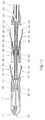
- a particularly expedient embodiment of the invention provides that several cutting body pairs are connected in series, which means that the Removal of deposits can be done faster.
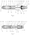
- the figures show medical instruments for removing deposits in Artery and / or vein walls, each with one that can be inserted into the vessels and at least partially hollow bodies 10-14 with one from the vessels executable pulling and / or actuating means 20 as well as in the pulling direction pointing and removing the deposits cutting bodies 21, 22 with Cutting edges 24 shown.
- the section 30 protruding into the respective body 10-14 of the base body 26, 27 is designed as a tube section in which an organ 32, 34 for the relative adjustment of the body 10 - 14 with reference to the Cutting body 21, 22 is arranged.
- the organ 32, 34 is as a piece of pipe or executed piece of wire that can be operated from the outside.
- the pivot axis 36 of the cutting body 21, 22 extends transversely to the pulling direction of the body 10 - 14.
- the cutting bodies 21 and 22 are designed as two-armed levers are in their rest positions completely or almost completely in the body 10 - 14 are accommodated.
- the base body 26 or 27 has one Stop section 38, the in the rest position of the cutting body 21 and 22nd almost free of distance to an end face 40 of the respective body 10-14 is arranged.
- the respective body 10-14 is essentially as one Hollow cylinder formed, the cutting body 21 and 22 in their rest position records.
- the end face 41 of the respective body 10 facing away from the user 14 has an opening 42 extending in the pulling direction, into which the End piece of the organ 32 or 34 protrudes and is fastened there.
- the ones from User turned away end face 41 of the respective body 10-14 is convex and edge-free.
- the figures also show that two cutting bodies 21, 22 with one common pivot axis 36 and one power arm and one load arm 43 and 44 are provided.
- the inner wall of the respective body 10 has 11, 12 pressure body 46, which in its operating position with the respective Power arm 43 and in its rest position with the respective load arm 44 Cutting body 21 and 22 are in pressure connection.
- the pressure body 46 are here as radial projections with sliding curves that extend in the axial direction extend, trained.
- the outer contour of the respective cutting body longitudinal section is arched, so that a continuous opening or Closing the cutter body is guaranteed.
- the organ 32, 34 designed as a piece of rope, pipe or wire carries clamping members 48, 49 and 50 (see FIGS. 8-11), which depend on the operating situation of the Cutting body 21 and 22 with the force or load arm 43 and 44 of the respective Cutters 21 and 22 work together.
- the clamp bodies 48, 49 and 50 are wedge-shaped in axial cross section and with their tapered End faces facing each other.
- two clamping bodies 48, 49 and 50 is provided, between which the pivot axis of the cutting bodies 21 and 22 is arranged.
- the clamping body 50 shown in FIG. 11 is of the basic body 26 worn and consists of an elastically deformable material.
- the part of the medical instrument shown in FIGS. 1 and 2 also has the peculiarity that the body 10 the cutting body 21 and 22 in their Rest position (Fig. 2) does not take up completely.
- the cutting edges 24 are however arranged in front of the stop 38, so that in this case there is none Cutting process can come.
- the cutting process is only then ensures when the body 10 an approximately maximum distance from the Has pivot axis 36, with its pressure element 46 on the force arms 43 Apply pressure so that the cutting edges 24 are arranged at a maximum from one another are and protrude beyond the base body 26, d.
- H. the outer circumference of the Base body 26 is smaller than the outer circumference of the two Cutting edges 24.
- the cutting bodies 21 and 22 on the section 30, which as Tube piece is formed are articulated, when moving the organ 32, which is also designed as a piece of pipe, the body 10 moves away, wherein force is exerted on the force arms 43.
- the organ 32 can Guide body, e.g. B. piece of wire, introduced from the opening 42nd protrudes and can be used to insert the instrument into the vessels.
- the pressure body 46 on the Load arms 44 apply pressure so that the instrument is the one shown in FIG Takes position.
- FIGS. 3 to 5 show part of a further instrument that can be used differs from the instrument according to FIGS. 1 and 2 in that the body 11 is dimensioned such that it is in the closed position or rest position of the instrument can fully accommodate both cutting bodies 21 and 22 (cf. FIG. 4).
- the outer contour of the cross section of the body 11 is circular.
- the base body 26 also has a cross section, so that the body 11 with the Base body 26 can be flush. There is an advantage to this measure in that the insertion of the instrument into the vessels is particularly easy.
- flanks 54 and 55 are formed as cutting bodies, so that not only the front, but also the long sides are used for cutting can.
- the organ 32 is dimensioned so that it is at the same time Guide an angioscope 3 and a guide body 1 can serve.
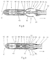
- the peculiarity of the instrument is that that the body 12 has a diameter reduction in the central region, so that thereby at the same time a head start for the actuation of the force or Load arm of the respective cutting body is formed.
- the base body 27 has a lateral transverse bore 61 into which a guide body can be introduced, whose free end can protrude from the opening 42.
- Organ 34 may be formed as a piece of wire.
- the instrument shown in FIG. 6 is also provided with a similar transverse bore 61 provided, wherein the body 11 is dimensioned so that it full of the cutting body can accommodate, as disclosed in the case of the instrument of FIG. 3.
- the organ 32 or 34 designed as a piece of rope, pipe or wire the Clamping body 48, 49 and 50 carries, depending on the operating position of the Cutting body 21 and 22 with the force or load arm 43 and 44 of the respective Cutters 21 and 22 work together.
- the clamping body 48 and 49 adjusted with respect to the pivot axis 36 being on the respective Apply pressure on the inside of the load arm or power arm so that it presses inwards or be pivoted outside.
- the organ 32 a piece of wire.
- the body 14 into the vessel To be able to insert easily is in the front end of the body 14 Cross bore 60 formed, into which a piece of guide wire can be introduced.
- the peculiarity of the instrument according to FIG. 11 is that the Clamping body 50 are firmly connected to section 30 and from one resiliently deformable material. Therefore, it is only required that To move clamp body 48. Is the clamping body 48 with the force arms 43 not in engagement, then the clamping bodies 55 exert force on the load arms 44, so that they are swung out and the position shown in Fig. 11 take in.
- the part of a medical instrument shown in FIG. 12 stands out characterized in that two pairs of cutting bodies 21, 22 are arranged in series and are adjustable by the same actuating means 20. In general, could three, four or more pairs of cutting bodies can also be used. All in general, the cutting body could be created as in the Claims is defined.
- the cutting edges 24 are essentially arranged outside the body, wherein they protrude beyond the base body 26 and when operating the instrument in the pulling direction with the inner wall of the tubes in Active connection can be brought.
Abstract
Description
Die Erfindung betrifft ein medizinisches Instrument nach dem Oberbegriff des
Anspruches 1.The invention relates to a medical instrument according to the preamble of
Bei herkömmlichen Instrumenten der eingangs genannten Art, wie sie z. B. in der US-PS 4765 332 beschrieben sind, ist ein etwa zylinderförmiger Grundkörper mit in Zugrichtung weisenden Schneideabschnitten vorgesehen, die ebenfalls zylinderförmig sind. Die scharfen Kanten der Schneideabschnitte verjüngen sich von innen nach aussen, was zur Verletzung auch gesunder Gefäße führen kann. Ein weiterer Nachteil, mit dem das bekannte Instrument behaftet ist, besteht darin, dass eine Anpassung an die Arterien- bzw. Venenwände nur im begrenzten Umfang möglich ist.In conventional instruments of the type mentioned, as z. B. in the US-PS 4765 332 are described, is an approximately cylindrical body provided in the pulling direction cutting sections, which also are cylindrical. The sharp edges of the cutting sections taper from the inside out, which can also damage healthy vessels. Another disadvantage with which the known instrument is afflicted is that that adaptation to the artery or vein walls is limited Scope is possible.
Schließlich ist in der WO-A-9002523 ein medizinisches Instrument, gemäß dem
Oberbegriff des Anspruchs 1, offenbart, bei dem die schalenförmigen Teile
(Schneidekörper) mit einem Spannkörper zusammenarbeiten. Durch diesen
Spannkörper ist der Abstand der Schneidekanten voneinander zwar einstellbar, die
Handhabung mit dem Instrument ist jedoch umständlich.Finally, in WO-A-9002523 is a medical instrument according to which
The preamble of
Ausgehend vom obigen Stand der Technik liegt der Erfindung die Aufgabe zugrunde, das gattungsgemäße Instrument so weiter zu bilden, dass sein effektiver Querschnitt einfach vergrößert und den Venen angepasst werden kann.Starting from the above prior art, the object of the invention to further develop the generic instrument so that it is more effective Cross section simply enlarged and adapted to the veins.
Die gestelte Aufgabe wird erfindungsgemäß durch die Merkmale des Anspruches
1 gelöst.The object presented is achieved by the features of the
Ein solches Instrument kann in das Gefäß mittels eines Katheters eingeführt werden, und zwar bis zur vorgesehenen Stelle, die durch Kontrastmittel lokalisiert werden kann. Der Katheter und der Körper werden so angeordnet, dass die Plaque zwischen dem Körper und dem Katheter angeordnet ist. Dann wird das Zugmittel betätigt und die vorgesehene Stelle wird abgeschabt. Dieser Vorgang kann so oft wiederholt werden, bis eine glatte Innenwand vorhanden ist. Die beim Hoben entstandenen Späne können entweder abgesaugt oder durch den Körper, der nach dem Eingriff aus der Arterie herausgezogen wird, mitgenommen werden.Such an instrument can be inserted into the vessel by means of a catheter to the intended location, which is localized by contrast media can be. The catheter and body are arranged so that the plaque is arranged between the body and the catheter. Then the traction device actuated and the intended location is scraped off. This can happen so often can be repeated until there is a smooth inner wall. The one when lifting Shavings created can either be suctioned off or through the body after the procedure is pulled out of the artery.
Weitere zweckmäßige und vorteilhafte Ausgestaltungen der Erfindung gehen aus den Unteransprüchen hervor.Further expedient and advantageous embodiments of the invention are based the subclaims.
Eine zweckmäßige Ausgestaltung der Erfindung sieht vor, dass der in den Körper hineinragende Abschnitt des Grundkörpers als ein Rohrabschnitt ausgebildet ist, in dem ein Organ zur relativen Verstellung des Körpers mit Bezug auf den Schneidekörper angeordnet ist. An expedient embodiment of the invention provides that the in the body protruding section of the base body is designed as a tube section, in which is an organ for the relative adjustment of the body in relation to the Cutting body is arranged.
Dabei ist es zweckmäßig, wenn das Organ als ein Rohrstück oder Drahtstück ausgeführt ist, das von aussen her betätigbar ist. Durch die Betätigung des Organs wird auf die Schneidekörper Druck ausgeübt, so dass sie den effektiven Querschnitt des Schneidekörpers entweder vergrößern oder verkleinern, und zwar abhängig davon, ob der Körper zum Benutzer hin oder von diesem weg bewegt wird.It is useful if the organ as a piece of pipe or piece of wire is executed, which can be operated from the outside. By operating the organ pressure is exerted on the cutting bodies so that they are effective Either increase or decrease the cross-section of the cutting body, namely depending on whether the body moves towards or away from the user becomes.
Eine weitere zweckmäßige Ausgestaltung sieht vor, dass die Schwenkachse der Schneidekörper sich quer zur Zugrichtung des Körpers erstreckt. Dadurch wird sichergestellt, dass die Schneidekanten zum Benutzer hin weisen und die Schneidekörper ihre wirksame bzw. unwirksame Position einnehmen können. Gemäß dem Erfindungsgedanken werden die Schneidekörper als zweiarmige Hebel ausgebildet, wobei die zwei Schneidkörper eine gemeinsame Schwenkachse und jeweils einen Kraft- und einen Lastarm aufweisen. Die Schneidekörper können in ihrer Ruhestellung vollständig oder annähernd vollständig im Körper untergebracht werden. Dabei kann der Grundkörper einen Anschlagabschnitt aufweisen, der in Ruhestellung der Schneidekörper annähernd abstandsfrei zu einer Stirnseite des Körpers angeordnet ist. Der Vorteil dieser Maßnahme besteht insbesondere darin, dass das Einbringen des Instruments in Gefäße deutlich erleichtert wird, da in diesem Fall die Schneidekanten mit dem Gefäß nicht in Berührung kommen.Another useful embodiment provides that the pivot axis of the Cutting body extends transversely to the direction of pull of the body. This will ensures that the cutting edges point towards the user and the Cutting body can take their effective or ineffective position. According to the concept of the invention, the cutting bodies are two-armed levers formed, the two cutting bodies having a common pivot axis and each have a power arm and a load arm. The cutting body can be in completely or almost completely housed in their rest position become. The base body can have a stop section, which in Rest position of the cutting body almost without distance to an end face of the Body is arranged. The advantage of this measure is in particular that the introduction of the instrument into vessels is made significantly easier since in In this case, the cutting edges do not come into contact with the vessel.
Die Innenwand des Körpers kann Druckkörper aufweisen, die in ihrer Betriebsstellung mit dem jeweiligen Kraftarm und in ihrer Ruhestellung mit dem jeweiligen Lastarm der Schneidekörper in Druckverbindung stehen. Die Druckkörper können als radiale Vorsprünge mit Gleitkurven ausgebildet sein. Der Vorteil dieser Maßnahmen besteht darin, dass durch axiale Versetzung des Körpers in Zugrichtung die Schneidekörper entweder geöffnet oder geschlossen werden. Beim Öffnen fahren die Schneidekörper aus dem Körper heraus, dabei wird auf den jeweiligen Kraftarm des Schneidekörpers seitens des Körpers Druck ausgeübt, so dass sich die Schneidekörper öffnen und außerhalb des Körpers angeordnet sind. Die Schneidekanten der Schneidekörper definieren hierbei einen Kreis oder eine Ellipse, der bzw. die außerhalb des Körpers angeordnet ist/sind. Um die Schneidekörper kontinuierlich betätigen zu können, ist vorgesehen, dass das Außenprofil des jeweiligen Schneidekörper-Längsschnittes bogenförmig ist. Durch diese Maßnahmen wird ein allmähliches Öffnen bzw. Schließen der Schneidekörper sichergestellt.The inner wall of the body can have pressure bodies which in its Operating position with the respective power arm and in its rest position with the the respective load arm of the cutting bodies are in pressure connection. The Pressure bodies can be designed as radial projections with sliding curves. Of the The advantage of these measures is that by axially displacing the body the cutting bodies are either opened or closed in the pulling direction. When opening, the cutting bodies move out of the body, thereby the respective force arm of the cutting body exerted pressure on the part of the body, so that the cutting bodies open and are arranged outside the body. The cutting edges of the cutting bodies define a circle or one Ellipse that is located outside the body. To the To be able to operate the cutting body continuously, it is provided that External profile of the respective cutting body longitudinal section is arcuate. By these measures will be a gradual opening or closing of the cutting body ensured.
Ferner ist vorgesehen, dass der Körper im Wesentlichen als ein Hohlzylinder ausgebildet ist, der die Schneidekörper in ihrer Ruhestellung aufnimmt.It is also provided that the body is essentially a hollow cylinder is formed, which receives the cutting body in its rest position.
Eine weitere zweckmäßige Ausgestaltung der Erfindung sieht vor, dass die vom Benutzer abgekehrte Stirnseite der Körper eine in Zugrichtung sich erstreckende Öffnung aufweist. Die Öffnung kann zur Aufnahme eines Führungsmittels, z. B. eines dünnen Drahtstückes, dienen, durch das die Einbringung des Instruments an die vorgesehene Stelle erleichtert werden kann. Dabei ist es zweckmäßig, wenn die vom Benutzer abgekehrte Stirnseite des Körpers konvex und kantfrei ist.Another expedient embodiment of the invention provides that the Users face away from the front of the body extending in the pulling direction Has opening. The opening can accommodate a guide means, for. B. a thin piece of wire, through which the insertion of the instrument the intended position can be facilitated. It is useful if the face of the body turned away from the user is convex and free of edges.
Eine weitere zweckmäßige Ausgestaltung sieht vor, dass das als Seil-, Rohr- oder Drahtstück ausgebildete Organ Klemmkörper trägt, die abhängig von der Betriebslage der Schneidekörper mit dem Kraft- bzw. Lastarm des jeweiligen Schneidekörpers zusammenarbeiten. Dabei können die Klemmkörper im axialen Querschnitt keilförmig ausgebildet und mit ihren verjüngten Stirnseiten einander zugekehrt sein. Ferner ist es besonders zweckmäßig, wenn zwei Klemmkörper vorgesehen sind, zwischen denen die Schwenkachse der Schneidekörper angeordnet ist. Einer der Klemmkörper kann hierbei vom Grundkörper getragen sein und aus einem elastisch verformbaren Werkstoff bestehen. In diesem Fall übt nur einer der Klemmkörper Relativbewegungen mit Bezug auf die Schwenkachse der Schneidekörper aus.Another expedient embodiment provides that the rope, pipe or Wire piece trained organ carries sprags depending on the Operating position of the cutting body with the power or load arm of the respective Work the cutting body together. The sprags can be axial Cross-section wedge-shaped and with their tapered end faces to each other to be turned. Furthermore, it is particularly expedient if two clamping bodies are provided, between which the pivot axis of the cutting body is arranged. One of the clamping bodies can be carried by the base body be and consist of an elastically deformable material. In this case, exercise only one of the clamping bodies relative movements with respect to the pivot axis the cutting body.
Eine vorteilhafte Ausgestaltung der Erfindung sieht vor, dass die an die Schneidekanten sich anschließenden Flanken der Schneidekörper zumindest teilweise mit Schneideabschnitten versehen sind. Durch diese Maßnahmen ist sichergestellt, dass beim Schließen der Schneidekörper nicht nur die stirnseitigen Schneidekanten, sondern auch die in Längsrichtung der Schneidekörper sich erstreckenden Kanten als Schneideorgane wirken.An advantageous embodiment of the invention provides that the Cutting edges adjoining flanks of the cutting body at least are partially provided with cutting sections. Through these measures ensures that when closing the cutting body not only the front Cutting edges, but also in the longitudinal direction of the cutting body itself extending edges act as cutting organs.
Schließlich sieht eine besonders zweckmäßige Ausgestaltung der Erfindung vor, dass mehrere Schneidekörper-Paare in Serie geschaltet sind, wodurch die Beseitigung der Ablagerungen schneller erfolgen kann.Finally, a particularly expedient embodiment of the invention provides that several cutting body pairs are connected in series, which means that the Removal of deposits can be done faster.
Einige Ausführungsbeispiele der Erfindung sind in der Zeichnung schematisch dargestellt und werden im Folgenden näher erläutert.Some embodiments of the invention are schematic in the drawing are shown and are explained in more detail below.
Es zeigen
- Fig. 1
- einen axialen Querschnitt eines Teiles der ersten Ausführungsform des Instruments in Betriebsstellung,
- Fig. 2
- das in Fig. 1 dargestellte Instrument in Ruhestellung,
- Fig. 3
- eine zweite Ausführungsform des Instrumentes in Betriebsstellung,
- Fig. 4
- das in Fig. 3 dargestellte Instrument in Ruhestellung,
- Fig. 5
- einen Schnitt entlang der Linie A-A,
- Fig. 6
- eine weitere Ausführungsform des Instrumentes in seiner Betriebsstellung,
- Fig. 7
- eine weitere Ausführungsform des Instrumentes in seiner Schließstellung,
- Fig. 8
- ein Instrument mit Druckkörpern in Betriebsstellung,
- Fig. 9
- das in Fig. 8 dargestellte Instrument in Ruhestellung,
- Fig. 10
- ein Instrument mit Klemmkörpern und einer Querbohrung in Betriebsstellung,
- Fig. 11
- ein Instrument mit elastischen Klemmkörpern in Betriebsstellung und
- Fig. 12
- das Instrument nach Fig. 1 in Tandem-Ausführung.
- Fig. 1
- 3 shows an axial cross section of a part of the first embodiment of the instrument in the operating position,
- Fig. 2
- the instrument shown in Fig. 1 in the rest position,
- Fig. 3
- a second embodiment of the instrument in the operating position,
- Fig. 4
- the instrument shown in Fig. 3 in the rest position,
- Fig. 5
- a section along the line AA,
- Fig. 6
- another embodiment of the instrument in its operating position,
- Fig. 7
- another embodiment of the instrument in its closed position,
- Fig. 8
- an instrument with pressure bodies in the operating position,
- Fig. 9
- 8 the instrument shown in the rest position,
- Fig. 10
- an instrument with sprags and a cross hole in the operating position,
- Fig. 11
- an instrument with elastic clamps in the operating position and
- Fig. 12
- 1 in tandem.
In den Figuren sind medizinische Instrumente zur Beseitigung von Ablagerungen in
Arterien- und/oder Venenwänden mit jeweils einem in die Gefäße einbringbaren
und zumindest teilweise hohlen Körper 10 - 14 mit einem aus den Gefäßen
ausführbaren Zug- und/oder Betätigungsmittel 20 sowie mit in Zugrichtung
weisenden und die Ablagerungen beseitigenden Schneidekörpern 21, 22 mit
Schneidekanten 24 dargestellt. Dabei ist ein in den Körper 10 - 14 zumindest
teilweise hineinragender Grundkörper 26, 27 vorgesehen, an dem die in
Zugrichtung sich erstreckenden Schneidekörper 21, 22 angelenkt sind und ihre
Betriebs- bzw. Ruhestellung durch Verstellung des Körpers 10 - 14 in Zugrichtung
definierbar ist. Der in den jeweiligen Körper 10 - 14 hineinragende Abschnitt 30
des Grundkörpers 26, 27 ist als ein Rohrabschnitt ausgebildet, in dem ein Organ
32, 34 zur relativen Verstellung des Körpers 10 - 14 mit Bezug auf den
Schneidekörper 21, 22 angeordnet ist. Das Organ 32, 34 ist als ein Rohrstück
oder Drahtstück ausgeführt, das von aussen her betätigbar ist. Die Schwenkachse
36 der Schneidekörper 21, 22 erstreckt sich quer zur Zugrichtung des Körpers 10 -
14.The figures show medical instruments for removing deposits in
Artery and / or vein walls, each with one that can be inserted into the vessels
and at least partially hollow bodies 10-14 with one from the vessels
executable pulling and / or actuating means 20 as well as in the pulling direction
pointing and removing the
Man erkennt, dass die Schneidekörper 21 und 22 als zweiarmige Hebel ausgebildet
sind, die in ihren Ruhestellungen vollständig oder annähernd vollständig im Körper
10 - 14 untergebracht sind. Der Grundkörper 26 bzw. 27 weist einen
Anschlagabschnitt 38 auf, der in Ruhestellung der Schneidekörper 21 und 22
annähernd abstandsfrei zu einer Stirnseite 40 des jeweiligen Körpers 10 - 14
angeordnet ist. Der jeweilige Körper 10 - 14 ist im Wesentlichen als ein
Hohlzylinder ausgebildet, der die Schneidekörper 21 und 22 in ihrer Ruhestellung
aufnimmt. Die vom Benutzer abgekehrte Stirnseite 41 des jeweiligen Körpers 10 -
14 weist eine in Zugrichtung sich erstreckende Öffnung 42 auf, in die das
Endstück des Organs 32 bzw. 34 hereinragt und dort befestigt ist. Die vom
Benutzer abgekehrte Stirnseite 41 des jeweiligen Körpers 10 - 14 ist konvex und
kantfrei.It can be seen that the cutting
Die Figuren lassen ferner erkennen, dass zwei Schneidekörper 21, 22 mit einer
gemeinsamen Schwenkachse 36 und jeweils einem Kraft- und einem Lastarm 43
und 44 vorgesehen sind. Dabei weist die Innenwand des jeweiligen Körpers 10,
11, 12 Druckkörper 46 auf, die in ihrer Betriebsstellung mit dem jeweiligen
Kraftarm 43 und in ihrer Ruhestellung mit dem jeweiligen Lastarm 44 der
Schneidekörper 21 und 22 in Druckverbindung stehen. Die Druckkörper 46 sind
hierbei als radiale Vorsprünge mit Gleitkurven, die sich in axialer Richtung
erstrecken, ausgebildet. Der Aussenumriss des jeweiligen Schneidekörper-Längsschnittes
ist bogenförmig, so dass ein kontinuierliches Öffnen bzw.
Schließen der Schneidekörper gewährleistet ist.The figures also show that two cutting
Das als Seil-, Rohr- oder Drahtstück ausgebildete Organ 32, 34 trägt Klemmkörper
48, 49 und 50 (vgl. Fig. 8 - 11), die abhängig von der Betriebslage der
Schneidekörper 21 und 22 mit dem Kraft- bzw. Lastarm 43 und 44 des jeweiligen
Schneidekörpers 21 und 22 zusammenarbeiten. Die Klemmkörper 48, 49 und 50
sind im axialen Querschnitt keilförmig ausgebildet und mit ihren verjüngten
Stirnseiten einander zugekehrt. Hierbei sind jeweils zwei Klemmkörper 48, 49 und
50 vorgesehen, zwischen denen die Schwenkachse der Schneidekörper 21 und 22
angeordnet ist. Der in Fig. 11 dargestellte Klemmkörper 50 ist vom Grundkörper
26 getragen und besteht aus einem elastisch verformbaren Werkstoff.The
Das in Fig. 1 und 2 dargestellte Teil des medizinischen Instruments weist ferner
die Besonderheit auf, dass der Körper 10 die Schneidekörper 21 und 22 in ihrer
Ruhestellung (Fig. 2) nicht vollständig aufnimmt. Die Schneidekanten 24 sind
jedoch vor dem Anschlag 38 angeordnet, so dass es in diesem Fall zu keinem
Schneidevorgang kommen kann. Der Schneidevorgang wird erst dann
gewährleistet, wenn der Körper 10 einen etwa maximalen Abstand von der
Schwenkachse 36 aufweist, wobei seine Druckkörper 46 auf die Kraftarme 43
Druck ausüben, so dass die Schneidekanten 24 maximal voneinander angeordnet
sind und den Grundkörper 26 überragen, d. h. der Aussenumfang des
Grundkörpers 26 ist hierbei kleiner als der Aussenumfang der beiden
Schneidekanten 24. Da die Schneidekörper 21 und 22 am Abschnitt 30, der als
Rohrstück ausgebildet ist, angelenkt sind, wird beim Verschieben des Organs 32,
das ebenfalls als ein Rohrstück ausgebildet ist, der Körper 10 wegbewegt, wobei
auf die Kraftarme 43 Kraft ausgeübt wird. In das Organ 32 kann ein
Führungskörper, z. B. Drahtstück, eingebracht werden, das aus der Öffnung 42
herausragt und zur Einführung des Instrumentes in die Gefäße dienen kann. Wird
das Organ 32 in Richtung des Pfeiles betätigt, dann wird der Abstand des Körpers
10 von der Schwenkachse 36 minimiert, wobei die Druckkörper 46 auf die
Lastarme 44 Druck ausüben, so dass das Instrument die in Fig. 2 dargestellte
Position einnimmt.The part of the medical instrument shown in FIGS. 1 and 2 also has
the peculiarity that the
In den Figuren 3 bis 5 ist ein Teil eines weiteren Instruments dargestellt, das sich
von dem Instrument nach Figuren 1 und 2 dadurch unterscheidet, dass der Körper
11 so bemessen ist, dass er in Schließstellung bzw. Ruhestellung des Instruments
beide Schneidekörper 21 und 22 voll aufnehmen kann (vgl. Fig. 4). Der
Aussenumriss des Querschnittes des Körpers 11 ist kreisrund. Den gleichen
Querschnitt hat auch der Grundkörper 26, so dass der Körper 11 mit dem
Grundkörper 26 bündig abschließen kann. Ein Vorteil dieser Maßnahme besteht
darin, dass das Einbringen des Instruments in die Gefäße besonders einfach ist.FIGS. 3 to 5 show part of a further instrument that can be used
differs from the instrument according to FIGS. 1 and 2 in that the
Die Fig. 5 lässt erkennen, dass auch die in Zugrichtung des Instruments sich
erstreckenden Flanken 54 und 55 als Schneidekörper ausgebildet sind, so dass
nicht nur die Stirnseite, sondern auch die Längsseiten zum Schneiden dienen
können. Das Organ 32 ist hierbei so bemessen, dass es gleichzeitig auch zur
Führung eines Angioscopen 3 und eines Führungskörpers 1 dienen kann.5 shows that the direction of pull of the instrument can also be changed
extending
Die Besonderheit des Instruments, wie es in Fig. 7 dargestellt ist, besteht darin,
dass der Körper 12 im mittleren Bereich eine Durchmesserverringerung aufweist,
so dass hierdurch gleichzeitig ein Vorsprung für die Betätigung des Kraft- bzw.
Lastarmes des jeweiligen Schneidekörpers gebildet wird. Der Grundkörper 27
besitzt eine seitliche Querbohrung 61, in die ein Führungskörper einbringbar ist,
dessen freies Ende aus der Öffnung 42 herausragen kann. In diesem Fall kann das
Organ 34 als ein Drahtstück ausgebildet sein.The peculiarity of the instrument, as shown in Fig. 7, is that
that the
Mit einer ähnlichen Querbohrung 61 ist auch das in Fig. 6 dargestellte Instrument
versehen, wobei der Körper 11 so bemessen ist, dass er die Schneidekörper voll
aufnehmen kann, wie es im Falle des Instruments nach Fig. 3 offenbart ist.The instrument shown in FIG. 6 is also provided with a similar transverse bore 61
provided, wherein the
Die Besonderheiten der Instrumente nach den Figuren 8 bis 11 bestehen zunächst
darin, dass das als Seil-, Rohr- oder Drahtstück ausgebildete Organ 32 bzw. 34 die
Klemmkörper 48, 49 und 50 trägt, die abhängig von der Betriebslage der
Schneidekörper 21 und 22 mit dem Kraft- bzw. Lastarm 43 und 44 des jeweiligen
Schneidekörpers 21 und 22 zusammenarbeiten. Durch die relative Verstellung des
Organs 32 mit Bezug auf den Grundkörper 26 werden auch die Klemmkörper 48
und 49 mit Bezug auf die Schwenkachse 36 verstellt, wobei sie auf den jeweiligen
Last- bzw. Kraftarm innenseitig Druck ausüben, so dass diese nach innen bzw.
aussen verschwenkt werden. Im Falle des Instruments nach Fig. 10 ist das Organ
32 ein Drahtstück. Um auch in diesem Falle den Körper 14 in das Gefäß
problemlos einführen zu können, ist im stirnseitigen Endstück des Körpers 14 eine
Querbohrung 60 ausgebildet, in die ein Führungsdrahtstück einbringbar ist.The special features of the instruments according to FIGS. 8 to 11 initially exist
in that the
Die Besonderheit des Instruments nach Fig. 11 besteht darin, dass die
Klemmkörper 50 mit dem Abschnitt 30 fest verbunden sind und aus einem
elastisch verformbaren Werkstoff bestehen. Daher ist es erforderlich, nur den
Klemmkörper 48 zu versetzen. Ist der Klemmkörper 48 mit den Kraftarmen 43
nicht im Eingriff, dann üben die Klemmkörper 55 auf die Lastarme 44 Kraft aus, so
dass sie ausgeschwenkt werden und die in Fig. 11 dargestellte Position
einnehmen. The peculiarity of the instrument according to FIG. 11 is that the
Clamping
Der in Fig. 12 dargestellte Teil eines medizinischen Instruments zeichnet sich
dadurch aus, dass zwei Schneidekörper-Paare 21, 22 in Serie angeordnet sind
und von demselben Betätigungsmittel 20 verstellbar sind. Ganz allgemein könnten
auch drei, vier oder mehrere Schneidekörper-Paare eingesetzt werden. Ganz
allgemein könnten die Schneidekörper so geschaffen sein, wie es in den
Ansprüchen definiert ist.The part of a medical instrument shown in FIG. 12 stands out
characterized in that two pairs of cutting
Zusammenfassend kann festgestellt werden, dass das vorgeschlagene Instrument aus im Wesentlichen folgenden Teilen besteht:In summary, it can be said that the proposed instrument essentially consists of the following parts:
Grundkörper 26 und 27, an dem mindestens zwei Schneidekörper angelenkt sind,
die durch Verstellen des Körpers bzw. der Klemmkörper sich scherenartig öffnen
bzw. schließen. Im Betriebszustand sind die Schneidekanten 24 im Wesentlichen
ausserhalb des Körpers angeordnet, wobei sie den Grundkörper 26 überragen und
beim Betätigen des Instruments in Zugrichtung mit der Innenwand der Gefäße in
Wirkverbindung bringbar sind.
Claims (24)
gekennzeichnet durch
einen in den Körper (10-14) zumindest teilweise hineinragenden Grundkörper (26,27), an dem die in Zugrichtung sich erstreckenden und als angeformte Blättchenfeder ausgebildete Schneidekörper (21, 22) angelenkt sind.Medical instrument for removing deposits in arterial and / or vein walls with a body (10 - 14) that can be inserted into the vessels and is at least partially hollow, with a pulling and / or actuating means (20) that can be carried out from the vessels, as well as with a pulling direction and the deposits-removing cutting bodies (21, 22) with cutting edges (24),
marked by
a base body (26, 27) at least partially protruding into the body (10-14), to which the cutting bodies (21, 22), which extend in the pulling direction and are formed as a molded leaf spring, are articulated.
dadurch gekennzeichnet,
dass der in den Körper (10 - 14) hineinragende Abschnitt (30) des Grundkörpers (26, 27) als ein Rohrabschnitt ausgebildet ist, in dem ein Organ (32, 34) zur relativen Verstellung des Körpers (10 - 14) mit Bezug auf den Schneidekörper (21, 22) angeordnet ist. Instrument according to claim 1,
characterized,
that the section (30) of the base body (26, 27) projecting into the body (10 - 14) is designed as a tube section in which an organ (32, 34) for the relative adjustment of the body (10 - 14) with reference to the cutting body (21, 22) is arranged.
dadurch gekennzeichnet,
dass das Organ (32, 34) als ein Rohrstück oder Drahtstück ausgebildet ist, das von aussen her betätigbar ist.Instrument according to claim 1 or 2,
characterized,
that the organ (32, 34) is designed as a piece of pipe or wire that can be actuated from the outside.
dadurch gekennzeichnet,
dass die Schwenkachse (36) der Schneidekörper (21, 22) sich quer zur Zugrichtung des Körpers (10 - 14) erstreckt.Instrument according to one of claims 1 to 3,
characterized,
that the pivot axis (36) of the cutting body (21, 22) extends transversely to the direction of pull of the body (10 - 14).
dadurch gekennzeichnet,
dass die Schneidekörper (21, 22) als ein- oder zweiarmige Hebel ausgebildet sind, die in ihrer Ruhestellung vollständig oder annähernd vollständig im Körper (10 - 14) untergebracht sind.Instrument according to one of claims 1 to 4,
characterized,
that the cutting bodies (21, 22) are designed as one- or two-armed levers which are completely or almost completely accommodated in the body (10 - 14) in their rest position.
dadurch gekennzeichnet,
dass der Körper (26, 27) einen Anschlagabschnitt (38) aufweist, der in Ruhestellung der Schneidekörper (21, 22) annähernd abstandsfrei zu einer Stirnseite (40) des Körpers (10 - 14) angeordnet ist.Instrument according to one of claims 1 to 5,
characterized,
that the body (26, 27) has a stop section (38) which, in the rest position of the cutting bodies (21, 22), is arranged approximately without a distance from an end face (40) of the body (10 - 14).
dadurch gekennzeichnet,
dass der Körper (10-14) im Wesentlichen als ein Hohlzylinder ausgebildet ist, der die Schneidekörper (21, 22) in ihrer Ruhestellung aufnimmt. Instrument according to one of claims 1 to 6,
characterized,
that the body (10-14) is essentially designed as a hollow cylinder which receives the cutting bodies (21, 22) in their rest position.
dadurch gekennzeichnet,
dass die vom Benutzer abgekehrte Stirnseite (41) des Körpers (10 - 14) eine in Zugrichtung sich erstreckende Öffnung (42) aufweist.Instrument according to one of claims 1 to 7,
characterized,
that the end face (41) of the body (10-14) facing away from the user has an opening (42) extending in the pulling direction.
dadurch gekennzeichnet,
dass die vom Benutzer abgekehrte Stirnseite (41) des Körpers (10 - 14) konvex und kantfrei ist.Instrument according to one of claims 1 to 8,
characterized,
that the end face (41) of the body (10 - 14) turned away from the user is convex and free of edges.
dadurch gekennzeichnet,
dass zwei Schneidekörper (21, 22) mit einer gemeinsamen Schwenkachse (36) und jeweils einem Kraft- und einem Lastarm (43, 44) vorgesehen sind.Instrument according to one of claims 1 to 9,
characterized,
that two cutting bodies (21, 22) with a common swivel axis (36) and each with a power arm and a load arm (43, 44) are provided.
dadurch gekennzeichnet,
dass die Innenwand des Körpers (10, 11, 12) Druckkörper (46) aufweist, die in ihrer Betriebsstellung mit dem jeweiligen Kraftarm (43) und in ihrer Ruhestellung mit dem jeweiligen Lastarm (44) der Schneidekörper (21, 22) in Druckverbindung stehen.Instrument according to one of claims 1 to 10,
characterized,
that the inner wall of the body (10, 11, 12) has pressure bodies (46) which are in pressure connection in their operating position with the respective power arm (43) and in their rest position with the respective load arm (44) of the cutting bodies (21, 22) .
dadurch gekennzeichnet,
dass die Druckkörper (46) als radiale Vorsprünge mit Gleitkurven ausgebildet sind. Instrument according to one of claims 1 to 11,
characterized,
that the pressure body (46) are designed as radial projections with sliding curves.
dadurch gekennzeichnet,
dass das Außenprofil des jeweiligen Schneidekörper-Längsschnittes bogenförmig ist.Instrument according to one of claims 1 to 12,
characterized,
that the outer profile of the respective cutting body longitudinal section is arc-shaped.
dadurch gekennzeichnet,
dass das als ein Seil-, Rohr- oder Drahtstück ausgebildete Organ (32, 34) Klemmkörper (48, 49, 50) trägt, die abhängig von der Betriebslage der Schneidekörper (21, 22) mit dem Kraft- bzw. Lastarm (43, 44) des jeweiligen Schneidekörpers (21, 22) zusammenarbeiten.Instrument according to one of claims 1 to 13,
characterized,
that the organ (32, 34) designed as a piece of rope, pipe or wire carries clamping bodies (48, 49, 50) which, depending on the operating position of the cutting bodies (21, 22) with the force or load arm (43, 44) of the respective cutting body (21, 22) work together.
dadurch gekennzeichnet,
dass die Klemmkörper (48, 49, 50) im axialen Querschnitt keilförmig ausgebildet und mit ihren verjüngten Stirnseiten einander zugekehrt sind.Instrument according to one of claims 1 to 14,
characterized,
that the clamping bodies (48, 49, 50) are wedge-shaped in axial cross-section and face one another with their tapered end faces.
dadurch gekennzeichnet,
dass zwei Klemmkörper (48, 49, 50) vorgesehen sind, zwischen denen die Schwenkachse der Schneidekörper (21, 22) angeordnet ist.Instrument according to one of claims 1 to 15,
characterized,
that two clamping bodies (48, 49, 50) are provided, between which the pivot axis of the cutting bodies (21, 22) is arranged.
dadurch gekennzeichnet,
dass einer der Klemmkörper (50) vom Grundkörper (26) getragen ist und aus einem elastisch verformbaren Werkstoff besteht. Instrument according to one of claims 1 to 16,
characterized,
that one of the clamping bodies (50) is carried by the base body (26) and consists of an elastically deformable material.
dadurch gekennzeichnet,
dass der Körper (10 - 14) und/oder der Grundkörper (26, 27) Querbohrungen (60, 61) für Führungsmittel aufweist/aufweisen.Instrument according to one of claims 1 to 17,
characterized,
that the body (10-14) and / or the base body (26, 27) has / have transverse bores (60, 61) for guide means.
dadurch gekennzeichnet,
dass die Schneidekörper (21, 22) einen als Kammer ausgebildeten Hohlraum (52) definieren, durch den sich das Organ (35) hindurch erstreckt.Instrument according to one of claims 1 to 18,
characterized,
that the cutting bodies (21, 22) define a cavity (52) designed as a chamber, through which the organ (35) extends.
dadurch gekennzeichnet,
dass die an die Schneidekanten (24) sich anschließenden Flanken (54, 55) der Schneidekörper (21, 22) zumindest teilweise mit Schneideabschnitten versehen sind.Instrument according to one of claims 1 to 19,
characterized,
that the flanks (54, 55) of the cutting bodies (21, 22) adjoining the cutting edges (24) are at least partially provided with cutting sections.
gekennzeichnet durch
einen in den Körper (10 - 14) zumindest teilweise hineinragenden Grundkörper (26, 27), mit dem die in Zugrichtung sich erstreckenden Schneidekörper (21, 22) z.B. durch Schrauben, Schweißen, Hartlötung, Kaltverformung oder dergleichen fest verbunden sind und ihre Betriebs- bzw. Ruhestellung durch Verstellung des Körpers (10 - 14) in Zugrichtung definierbar ist.Instrument according to one of claims 1 to 20,
marked by
a base body (26, 27) at least partially protruding into the body (10 - 14), with which the cutting bodies (21, 22) extending in the pulling direction are firmly connected, for example by screwing, welding, brazing, cold working or the like, and their operational or rest position can be defined by adjusting the body (10 - 14) in the pulling direction.
dadurch gekennzeichnet,
dass die Schneidekörper (21, 22) aus einem elastisch verformbaren Werkstoff wie Metall, Keramik, Kunststoff oder aus Legierungen bestehen. Instrument according to one of claims 1 to 21,
characterized,
that the cutting bodies (21, 22) consist of an elastically deformable material such as metal, ceramic, plastic or alloys.
dadurch gekennzeichnet,
dass der Körper (10 -14), der Grundkörper (26, 27) und Teile des Schneidekörpers (21, 22) aus elektrisch leitendem Werkstoff bestehen und bis auf die scharfen Schneidekanten mit einem Isolator beschichtet sind.Instrument according to one of claims 1 to 22,
characterized,
that the body (10 -14), the base body (26, 27) and parts of the cutting body (21, 22) consist of electrically conductive material and are coated with an insulator except for the sharp cutting edges.
dadurch gekennzeichnet,
dass mindestens zwei Schneidekörperpaare (21, 22) in Serie angeordnet sind.Instrument according to one of claims 1 to 23,
characterized,
that at least two pairs of cutting bodies (21, 22) are arranged in series.
Applications Claiming Priority (3)
| Application Number | Priority Date | Filing Date | Title |
|---|---|---|---|
| DE4307642 | 1993-03-11 | ||
| DE4307642A DE4307642C1 (en) | 1993-03-11 | 1993-03-11 | Medical instrument for dispersal of deposits in arteries and/or veins - has partly hollow body with basic body to which cutters are attached having cutting edges pointing in draw direction |
| EP94911137A EP0639954B1 (en) | 1993-03-11 | 1994-03-09 | Medical instrument for atherectomy |
Related Parent Applications (1)
| Application Number | Title | Priority Date | Filing Date |
|---|---|---|---|
| EP94911137A Division EP0639954B1 (en) | 1993-03-11 | 1994-03-09 | Medical instrument for atherectomy |
Publications (2)
| Publication Number | Publication Date |
|---|---|
| EP0906748A2 true EP0906748A2 (en) | 1999-04-07 |
| EP0906748A3 EP0906748A3 (en) | 1999-05-26 |
Family
ID=6482470
Family Applications (3)
| Application Number | Title | Priority Date | Filing Date |
|---|---|---|---|
| EP94911137A Expired - Lifetime EP0639954B1 (en) | 1993-03-11 | 1994-03-09 | Medical instrument for atherectomy |
| EP98122558A Withdrawn EP0909552A3 (en) | 1993-03-11 | 1994-03-09 | Medical instrument for atherectomy |
| EP98122557A Withdrawn EP0906748A3 (en) | 1993-03-11 | 1994-03-09 | Medical instrument for atherectomy |
Family Applications Before (2)
| Application Number | Title | Priority Date | Filing Date |
|---|---|---|---|
| EP94911137A Expired - Lifetime EP0639954B1 (en) | 1993-03-11 | 1994-03-09 | Medical instrument for atherectomy |
| EP98122558A Withdrawn EP0909552A3 (en) | 1993-03-11 | 1994-03-09 | Medical instrument for atherectomy |
Country Status (7)
| Country | Link |
|---|---|
| US (1) | US5725543A (en) |
| EP (3) | EP0639954B1 (en) |
| JP (1) | JPH07509642A (en) |
| AT (1) | ATE181224T1 (en) |
| CH (1) | CH685368A5 (en) |
| DE (2) | DE4307642C1 (en) |
| WO (1) | WO1994020033A1 (en) |
Families Citing this family (29)
| Publication number | Priority date | Publication date | Assignee | Title |
|---|---|---|---|---|
| DE19507560A1 (en) * | 1995-03-03 | 1996-09-05 | Heiss Josef Medizintech | Medical instrument for intravenous use |
| US6096054A (en) * | 1998-03-05 | 2000-08-01 | Scimed Life Systems, Inc. | Expandable atherectomy burr and method of ablating an occlusion from a patient's blood vessel |
| US6561998B1 (en) | 1998-04-07 | 2003-05-13 | Transvascular, Inc. | Transluminal devices, systems and methods for enlarging interstitial penetration tracts |
| US6350271B1 (en) | 1999-05-17 | 2002-02-26 | Micrus Corporation | Clot retrieval device |
| EP1125556A1 (en) * | 2000-02-18 | 2001-08-22 | Medsys S.A. | Uterine manipulator |
| US6451037B1 (en) | 2000-11-22 | 2002-09-17 | Scimed Life Systems, Inc. | Expandable atherectomy burr with metal reinforcement |
| US6800083B2 (en) | 2001-04-09 | 2004-10-05 | Scimed Life Systems, Inc. | Compressible atherectomy burr |
| US7179269B2 (en) * | 2002-05-20 | 2007-02-20 | Scimed Life Systems, Inc. | Apparatus and system for removing an obstruction from a lumen |
| US7131981B2 (en) * | 2003-03-25 | 2006-11-07 | Angiodynamics, Inc. | Device and method for converting a balloon catheter into a cutting balloon catheter |
| US9492192B2 (en) | 2006-06-30 | 2016-11-15 | Atheromed, Inc. | Atherectomy devices, systems, and methods |
| US8007506B2 (en) | 2006-06-30 | 2011-08-30 | Atheromed, Inc. | Atherectomy devices and methods |
| US9314263B2 (en) * | 2006-06-30 | 2016-04-19 | Atheromed, Inc. | Atherectomy devices, systems, and methods |
| US8628549B2 (en) | 2006-06-30 | 2014-01-14 | Atheromed, Inc. | Atherectomy devices, systems, and methods |
| US20080004645A1 (en) * | 2006-06-30 | 2008-01-03 | Atheromed, Inc. | Atherectomy devices and methods |
| US20090018566A1 (en) | 2006-06-30 | 2009-01-15 | Artheromed, Inc. | Atherectomy devices, systems, and methods |
| US20080045986A1 (en) | 2006-06-30 | 2008-02-21 | Atheromed, Inc. | Atherectomy devices and methods |
| CA2656594A1 (en) | 2006-06-30 | 2008-01-10 | Atheromed, Inc. | Atherectomy devices and methods |
| US8361094B2 (en) | 2006-06-30 | 2013-01-29 | Atheromed, Inc. | Atherectomy devices and methods |
| US20110112563A1 (en) * | 2006-06-30 | 2011-05-12 | Atheromed, Inc. | Atherectomy devices and methods |
| US8070762B2 (en) | 2007-10-22 | 2011-12-06 | Atheromed Inc. | Atherectomy devices and methods |
| US8236016B2 (en) | 2007-10-22 | 2012-08-07 | Atheromed, Inc. | Atherectomy devices and methods |
| WO2013023121A1 (en) | 2011-08-11 | 2013-02-14 | Boston Scientific Scimed, Inc. | Expandable scaffold with cutting elements mounted thereto |
| EP2765930B1 (en) | 2011-10-13 | 2018-09-26 | Atheromed, Inc. | Atherectomy apparatus |
| US9364255B2 (en) | 2011-11-09 | 2016-06-14 | Boston Scientific Scimed, Inc. | Medical cutting devices and methods of use |
| DE102015101418B4 (en) * | 2014-02-04 | 2018-05-30 | Takatoshi FURUYA | Venous valve cutting device and method for its production |
| US10478213B2 (en) * | 2015-06-25 | 2019-11-19 | Covidien Lp | Tissue-removing catheter with adjustable cross-sectional dimension |
| EP4295892A3 (en) | 2018-04-09 | 2024-03-06 | Boston Scientific Scimed, Inc. | Cutting balloon catheter |
| EP3856053B1 (en) * | 2019-02-28 | 2023-07-19 | C. R. Bard, Inc. | Active cutting catheter with housed expandable actuator |
| US11304723B1 (en) | 2020-12-17 | 2022-04-19 | Avantec Vascular Corporation | Atherectomy devices that are self-driving with controlled deflection |
Citations (2)
| Publication number | Priority date | Publication date | Assignee | Title |
|---|---|---|---|---|
| US4765332A (en) | 1986-07-14 | 1988-08-23 | Medinnovations, Inc. | Pullback atherectomy catheter system |
| WO1990002523A1 (en) | 1988-09-09 | 1990-03-22 | Issa, Hashim | Surgical instrument for atherectomy |
Family Cites Families (37)
| Publication number | Priority date | Publication date | Assignee | Title |
|---|---|---|---|---|
| US2868206A (en) * | 1956-07-25 | 1959-01-13 | Frederick G Stoesser | Intra luminal vein stripper |
| US3230949A (en) * | 1962-08-02 | 1966-01-25 | Puerto Rico Cancer League Hosp | Gastroesophageal catheter |
| DE1909080A1 (en) * | 1968-02-23 | 1969-09-04 | Rosengreen Karl Aksel Kjelgaar | Sofa bed |
| US3508553A (en) * | 1968-03-06 | 1970-04-28 | Maurice S Kanbar | Surgical vein stripping instrument for phlebectomies |
| DE1935856A1 (en) * | 1969-07-15 | 1971-02-04 | Erwin Stengel | Probe for removing ureter stones |
| US3764427A (en) * | 1970-02-19 | 1973-10-09 | Codman & Shurtleff | Vein stripping instrument |
| US3837345A (en) * | 1973-08-31 | 1974-09-24 | A Matar | Venous valve snipper |
| CH632659A5 (en) * | 1978-03-29 | 1982-10-29 | Intermedicat Gmbh | Device for Trendelenburg's operation |
| GB2044103A (en) * | 1979-03-21 | 1980-10-15 | Ross D N | Device for removing material from stenoses |
| US4273128A (en) * | 1980-01-14 | 1981-06-16 | Lary Banning G | Coronary cutting and dilating instrument |
| US4493321A (en) * | 1982-05-25 | 1985-01-15 | Leather Robert P | Venous valve cutter for the incision of valve leaflets in situ |
| EP0117519A1 (en) * | 1983-02-23 | 1984-09-05 | Johannes Dipl.-Ing. Theermann | Catheter |
| DE3320984A1 (en) * | 1983-06-10 | 1984-12-13 | Theermann, Johannes, Dipl.-Ing., 4300 Essen | Catheter |
| US4685458A (en) * | 1984-03-01 | 1987-08-11 | Vaser, Inc. | Angioplasty catheter and method for use thereof |
| US4957482A (en) * | 1988-12-19 | 1990-09-18 | Surgical Systems & Instruments, Inc. | Atherectomy device with a positive pump means |
| US4842579B1 (en) * | 1984-05-14 | 1995-10-31 | Surgical Systems & Instr Inc | Atherectomy device |
| US4747821A (en) * | 1986-10-22 | 1988-05-31 | Intravascular Surgical Instruments, Inc. | Catheter with high speed moving working head |
| US4760845A (en) * | 1987-01-14 | 1988-08-02 | Hgm Medical Laser Systems, Inc. | Laser angioplasty probe |
| US4794928A (en) * | 1987-06-10 | 1989-01-03 | Kletschka Harold D | Angioplasty device and method of using the same |
| US5053044A (en) * | 1988-01-11 | 1991-10-01 | Devices For Vascular Intervention, Inc. | Catheter and method for making intravascular incisions |
| US4886061A (en) * | 1988-02-09 | 1989-12-12 | Medinnovations, Inc. | Expandable pullback atherectomy catheter system |
| US4952215A (en) * | 1988-02-29 | 1990-08-28 | Boisurge, Inc. | Valvulotome with leaflet disruption heads and fluid supply |
| WO1989009029A1 (en) * | 1989-02-16 | 1989-10-05 | Taheri Syde A | Method and apparatus for removing venous valves |
| US5026383A (en) * | 1989-06-14 | 1991-06-25 | Nobles Anthony A | Apparatus for in-situ cutting of valves within veins and method therefor |
| US5100426A (en) * | 1989-07-26 | 1992-03-31 | Fts Engineering, Inc. | Catheter for performing an atherectomy procedure |
| US5049154A (en) * | 1989-08-07 | 1991-09-17 | Berkshire Research & Development, Inc. | Adjustable intra-luminal valvulotome |
| US5133725A (en) * | 1989-08-07 | 1992-07-28 | Berkshire Research And Development, Inc. | Adjustable intra-liminal valvulotome |
| US5071424A (en) * | 1989-08-18 | 1991-12-10 | Evi Corporation | Catheter atherotome |
| US5047041A (en) * | 1989-08-22 | 1991-09-10 | Samuels Peter B | Surgical apparatus for the excision of vein valves in situ |
| US5030201A (en) * | 1989-11-24 | 1991-07-09 | Aubrey Palestrant | Expandable atherectomy catheter device |
| US5074871A (en) * | 1989-12-07 | 1991-12-24 | Evi Corporation | Catheter atherotome |
| US5011490A (en) * | 1989-12-07 | 1991-04-30 | Medical Innovative Technologies R&D Limited Partnership | Endoluminal tissue excision catheter system and method |
| US5061240A (en) * | 1990-04-02 | 1991-10-29 | George Cherian | Balloon tip catheter for venous valve ablation |
| US5154724A (en) * | 1990-05-14 | 1992-10-13 | Andrews Winston A | Atherectomy catheter |
| US5085659A (en) * | 1990-11-21 | 1992-02-04 | Everest Medical Corporation | Biopsy device with bipolar coagulation capability |
| US5152772A (en) * | 1991-07-10 | 1992-10-06 | Sewell Jr Frank | Sphincterotomy catheter and method |
| CH685738A5 (en) * | 1993-03-25 | 1995-09-29 | Ferromec Sa | Medical instrument for removing deposits formed on the inner walls of the arteries or veins. |
-
1993
- 1993-03-11 DE DE4307642A patent/DE4307642C1/en not_active Expired - Fee Related
-
1994
- 1994-03-09 CH CH703/94A patent/CH685368A5/en not_active IP Right Cessation
- 1994-03-09 EP EP94911137A patent/EP0639954B1/en not_active Expired - Lifetime
- 1994-03-09 AT AT94911137T patent/ATE181224T1/en not_active IP Right Cessation
- 1994-03-09 EP EP98122558A patent/EP0909552A3/en not_active Withdrawn
- 1994-03-09 US US08/335,870 patent/US5725543A/en not_active Expired - Fee Related
- 1994-03-09 WO PCT/EP1994/000730 patent/WO1994020033A1/en active IP Right Grant
- 1994-03-09 DE DE59408412T patent/DE59408412D1/en not_active Expired - Fee Related
- 1994-03-09 EP EP98122557A patent/EP0906748A3/en not_active Withdrawn
- 1994-03-09 JP JP6519596A patent/JPH07509642A/en active Pending
Patent Citations (2)
| Publication number | Priority date | Publication date | Assignee | Title |
|---|---|---|---|---|
| US4765332A (en) | 1986-07-14 | 1988-08-23 | Medinnovations, Inc. | Pullback atherectomy catheter system |
| WO1990002523A1 (en) | 1988-09-09 | 1990-03-22 | Issa, Hashim | Surgical instrument for atherectomy |
Also Published As
| Publication number | Publication date |
|---|---|
| US5725543A (en) | 1998-03-10 |
| EP0639954A1 (en) | 1995-03-01 |
| EP0909552A3 (en) | 1999-05-26 |
| JPH07509642A (en) | 1995-10-26 |
| DE59408412D1 (en) | 1999-07-22 |
| CH685368A5 (en) | 1995-06-30 |
| DE4307642C1 (en) | 1994-06-09 |
| EP0906748A3 (en) | 1999-05-26 |
| WO1994020033A1 (en) | 1994-09-15 |
| ATE181224T1 (en) | 1999-07-15 |
| EP0909552A2 (en) | 1999-04-21 |
| EP0639954B1 (en) | 1999-06-16 |
Similar Documents
| Publication | Publication Date | Title |
|---|---|---|
| EP0906748A2 (en) | Medical instrument for atherectomy | |
| DE3126578C2 (en) | Two-legged suturing instrument for use in surgery | |
| DE69731096T2 (en) | PINZETTE, ESPECIALLY FOR BIOPSY | |
| DE2903471A1 (en) | SURGICAL INSTRUMENT | |
| DE3603344A1 (en) | DEVICE FOR CRUSHING STONES, ESPECIALLY KIDNEY AND GALLET STONES OR THE LIKE | |
| DE3741879A1 (en) | ENDOSCOPIC INSTRUMENT | |
| DE3918720A1 (en) | RETROGRAD CUTTING HOOK PUNCH | |
| EP1319372B1 (en) | Device for holding a trocar sleeve | |
| DE69822305T2 (en) | CLAMPING DEVICE, ESPECIALLY A BIOPSIEZANGE | |
| DE19619065C2 (en) | Trocar sleeve with a valve | |
| DE19707374C2 (en) | Medical dissection spatula with expandable spatula jaw parts | |
| DE102016001271A1 (en) | Transporter of a resectoscope | |
| DE19837403B4 (en) | Actuation unit for an endoscopic treatment instrument | |
| EP0797407A2 (en) | Surgical instrument | |
| EP0674877A1 (en) | Surgical instrument for the precise placement of a knot | |
| DE3733236A1 (en) | VENO HOOK | |
| DE690697C (en) | Cystoscopic instrument for crushing bladder stones | |
| DE4210984C2 (en) | Trocar for minimally invasive surgery | |
| EP3155973B1 (en) | Biopsy forceps | |
| DE8216373U1 (en) | Trocar sleeve | |
| DE2923105A1 (en) | Gall stone surgery instrument - has trocar sleeve insert with external elements increasing frictional resistance to axial movement | |
| DE3306213A1 (en) | Catheter | |
| DE19738306C2 (en) | Vascular clamp | |
| DE8303342U1 (en) | Medical grasping instrument | |
| EP1943968B1 (en) | Tubular surgical instrument |
Legal Events
| Date | Code | Title | Description |
|---|---|---|---|
| PUAI | Public reference made under article 153(3) epc to a published international application that has entered the european phase |
Free format text: ORIGINAL CODE: 0009012 |
|
| AC | Divisional application: reference to earlier application |
Ref document number: 639954 Country of ref document: EP |
|
| AK | Designated contracting states |
Kind code of ref document: A2 Designated state(s): CH DE FR GB IT LI |
|
| AX | Request for extension of the european patent |
Free format text: SI PAYMENT 990104 |
|
| PUAL | Search report despatched |
Free format text: ORIGINAL CODE: 0009013 |
|
| DAX | Request for extension of the european patent (deleted) | ||
| AK | Designated contracting states |
Kind code of ref document: A3 Designated state(s): CH DE FR GB IT LI |
|
| 17P | Request for examination filed |
Effective date: 19991126 |
|
| 111L | Licence recorded |
Free format text: 20001216 0100 SHERINE MED AG |
|
| 17Q | First examination report despatched |
Effective date: 20010607 |
|
| STAA | Information on the status of an ep patent application or granted ep patent |
Free format text: STATUS: THE APPLICATION IS DEEMED TO BE WITHDRAWN |
|
| 18D | Application deemed to be withdrawn |
Effective date: 20021221 |