EP0906539B1 - Insulation for structural components having three-dimensional external surfaces - Google Patents
Insulation for structural components having three-dimensional external surfaces Download PDFInfo
- Publication number
- EP0906539B1 EP0906539B1 EP97924851A EP97924851A EP0906539B1 EP 0906539 B1 EP0906539 B1 EP 0906539B1 EP 97924851 A EP97924851 A EP 97924851A EP 97924851 A EP97924851 A EP 97924851A EP 0906539 B1 EP0906539 B1 EP 0906539B1
- Authority
- EP
- European Patent Office
- Prior art keywords
- insulating
- insulation
- bellows
- compensator
- skin
- Prior art date
- Legal status (The legal status is an assumption and is not a legal conclusion. Google has not performed a legal analysis and makes no representation as to the accuracy of the status listed.)
- Expired - Lifetime
Links
- 238000009413 insulation Methods 0.000 title claims description 60
- 239000000463 material Substances 0.000 claims description 20
- 239000011810 insulating material Substances 0.000 claims description 13
- 229910052751 metal Inorganic materials 0.000 claims description 13
- 239000002184 metal Substances 0.000 claims description 13
- 239000003365 glass fiber Substances 0.000 claims description 12
- 239000004447 silicone coating Substances 0.000 claims description 12
- 239000011152 fibreglass Substances 0.000 claims description 10
- 238000007789 sealing Methods 0.000 claims description 10
- 229910000669 Chrome steel Inorganic materials 0.000 claims description 9
- 239000000835 fiber Substances 0.000 claims description 9
- 239000010705 motor oil Substances 0.000 claims description 8
- BPQQTUXANYXVAA-UHFFFAOYSA-N Orthosilicate Chemical compound [O-][Si]([O-])([O-])[O-] BPQQTUXANYXVAA-UHFFFAOYSA-N 0.000 claims description 6
- 229910000831 Steel Inorganic materials 0.000 claims description 6
- 239000010959 steel Substances 0.000 claims description 6
- 238000003466 welding Methods 0.000 claims description 5
- 230000005540 biological transmission Effects 0.000 claims description 3
- 238000005253 cladding Methods 0.000 claims 7
- 229920001296 polysiloxane Polymers 0.000 claims 3
- 238000010521 absorption reaction Methods 0.000 claims 1
- 239000003054 catalyst Substances 0.000 claims 1
- 230000003019 stabilising effect Effects 0.000 claims 1
- 239000004744 fabric Substances 0.000 description 13
- 210000001503 joint Anatomy 0.000 description 9
- 239000007789 gas Substances 0.000 description 5
- 230000006378 damage Effects 0.000 description 4
- 239000011521 glass Substances 0.000 description 4
- 239000011490 mineral wool Substances 0.000 description 4
- 229910052782 aluminium Inorganic materials 0.000 description 3
- XAGFODPZIPBFFR-UHFFFAOYSA-N aluminium Chemical compound [Al] XAGFODPZIPBFFR-UHFFFAOYSA-N 0.000 description 3
- 239000011888 foil Substances 0.000 description 3
- 239000012774 insulation material Substances 0.000 description 3
- 238000005266 casting Methods 0.000 description 2
- 238000011161 development Methods 0.000 description 2
- 230000018109 developmental process Effects 0.000 description 2
- 230000035515 penetration Effects 0.000 description 2
- 230000005855 radiation Effects 0.000 description 2
- 230000002787 reinforcement Effects 0.000 description 2
- 230000008646 thermal stress Effects 0.000 description 2
- 230000009286 beneficial effect Effects 0.000 description 1
- 230000009172 bursting Effects 0.000 description 1
- 230000003197 catalytic effect Effects 0.000 description 1
- 239000011093 chipboard Substances 0.000 description 1
- 230000004087 circulation Effects 0.000 description 1
- 238000002485 combustion reaction Methods 0.000 description 1
- 239000004020 conductor Substances 0.000 description 1
- 230000001419 dependent effect Effects 0.000 description 1
- 230000001066 destructive effect Effects 0.000 description 1
- 239000000428 dust Substances 0.000 description 1
- 230000000694 effects Effects 0.000 description 1
- 230000005284 excitation Effects 0.000 description 1
- 238000002474 experimental method Methods 0.000 description 1
- 238000007689 inspection Methods 0.000 description 1
- 238000009434 installation Methods 0.000 description 1
- 239000012212 insulator Substances 0.000 description 1
- 238000002955 isolation Methods 0.000 description 1
- 239000003921 oil Substances 0.000 description 1
- 230000010355 oscillation Effects 0.000 description 1
- 230000000149 penetrating effect Effects 0.000 description 1
- 238000009958 sewing Methods 0.000 description 1
- 239000000126 substance Substances 0.000 description 1
- XLYOFNOQVPJJNP-UHFFFAOYSA-N water Substances O XLYOFNOQVPJJNP-UHFFFAOYSA-N 0.000 description 1
Images

Classifications
-
- F—MECHANICAL ENGINEERING; LIGHTING; HEATING; WEAPONS; BLASTING
- F16—ENGINEERING ELEMENTS AND UNITS; GENERAL MEASURES FOR PRODUCING AND MAINTAINING EFFECTIVE FUNCTIONING OF MACHINES OR INSTALLATIONS; THERMAL INSULATION IN GENERAL
- F16L—PIPES; JOINTS OR FITTINGS FOR PIPES; SUPPORTS FOR PIPES, CABLES OR PROTECTIVE TUBING; MEANS FOR THERMAL INSULATION IN GENERAL
- F16L59/00—Thermal insulation in general
- F16L59/02—Shape or form of insulating materials, with or without coverings integral with the insulating materials
- F16L59/021—Shape or form of insulating materials, with or without coverings integral with the insulating materials comprising a single piece or sleeve, e.g. split sleeves; consisting of two half sleeves; comprising more than two segments
- F16L59/024—Shape or form of insulating materials, with or without coverings integral with the insulating materials comprising a single piece or sleeve, e.g. split sleeves; consisting of two half sleeves; comprising more than two segments consisting of two half sleeves
-
- F—MECHANICAL ENGINEERING; LIGHTING; HEATING; WEAPONS; BLASTING
- F16—ENGINEERING ELEMENTS AND UNITS; GENERAL MEASURES FOR PRODUCING AND MAINTAINING EFFECTIVE FUNCTIONING OF MACHINES OR INSTALLATIONS; THERMAL INSULATION IN GENERAL
- F16L—PIPES; JOINTS OR FITTINGS FOR PIPES; SUPPORTS FOR PIPES, CABLES OR PROTECTIVE TUBING; MEANS FOR THERMAL INSULATION IN GENERAL
- F16L59/00—Thermal insulation in general
- F16L59/10—Bandages or covers for the protection of the insulation, e.g. against the influence of the environment or against mechanical damage
-
- F—MECHANICAL ENGINEERING; LIGHTING; HEATING; WEAPONS; BLASTING
- F16—ENGINEERING ELEMENTS AND UNITS; GENERAL MEASURES FOR PRODUCING AND MAINTAINING EFFECTIVE FUNCTIONING OF MACHINES OR INSTALLATIONS; THERMAL INSULATION IN GENERAL
- F16L—PIPES; JOINTS OR FITTINGS FOR PIPES; SUPPORTS FOR PIPES, CABLES OR PROTECTIVE TUBING; MEANS FOR THERMAL INSULATION IN GENERAL
- F16L59/00—Thermal insulation in general
- F16L59/14—Arrangements for the insulation of pipes or pipe systems
- F16L59/16—Arrangements specially adapted to local requirements at flanges, junctions, valves or the like
- F16L59/21—Arrangements specially adapted to local requirements at flanges, junctions, valves or the like adapted for expansion-compensation devices
Definitions
- the invention relates to insulation according to the preamble of claim 1.
- Such insulations are used for thermal and acoustic insulation of machines, Internal combustion engines, especially turbochargers, exhaust pipes, gas and Steam turbines, line expansion joints, containers, and the like, increased on their surface Temperatures and especially mechanical vibrations occur and / or from which Go out noises, used.
- the invention includes thermal and acoustic insulation for exhaust pipes and turbochargers, such as for medium-speed diesel engines, which is quickly removed by hand in the case of inspection, revision and in the event of an accident and can be reassembled.
- EP 0 403 943 B1 describes thermal insulation for pipe expansion joints described, consisting of two half-shells, each half-shell one made of glass fabric with a dampened aluminum foil existing outer shell with integrated bellows and has an inner shell made of glass fabric with an integrated bellows.
- the end faces are lined with dimensionally stable half rings.
- Rock wool mats are used as insulation material used.
- the two insulating halves are made using temperature-resistant zippers held together. The insulation works as follows: The Insulator is installed between the ends of the subsequent fixed insulation (Sheet metal ends) of the pipeline clamped.
- the present invention is therefore based on the object of providing a flexible insulation system create that has good thermal and acoustic insulation properties, easy to install and is removable and also at high temperatures and strong vibrations of the component to be insulated has a long service life.
- the friction layer is adapted to the shape of the component and takes the vibration-related friction between the component and the shell element flat on only in the area of expansion joints or their bellows elements a concern of the shell elements is not desirable because of the functionality of bellows elements through adjacent or clamped insulation material or envelope areas and at the same time the insulation is destroyed. Therefore in the area of the expansion joints must be a tight connection of the connected, spaced from the compensator shell elements guaranteed be so that the space between the component and the insulation after is tightly sealed on the outside.
- the insulation system is easy to dismantle and reassemble and as with conventional ones Insulating cushion, its actual insulating body is soft to match the shape of the insulation to be able to adapt the insulating body. Care should be taken that the pipe branch can be integrated directly into the insulation component to create a homogeneous insulation component receive.
- the insulation system is dimensionally stable despite the soft insulating body. Where extreme Changes in length due to high temperatures (e.g. with exhaust pipes) due to metal expansion joints to be compensated for is the insulating component in the area of the compensator flexibly designed so that the insulation system the movements of the exhaust pipe participates. Otherwise the insulation system itself and / or the compensator could be destroyed become.
- the inner surface of the insulation system that lie on the body to be insulated is resistant to relative movements caused by mechanical vibrations become.
- the casing material of the insulation system is preferably at least one one-sided, but especially two-sided silicone coating to prevent penetration protected by hot engine oil.
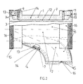
- FIG. 1 and FIG. 2 show the two insulating halves 1 and 2 joined together for an exhaust part 3 with integrated cylinder outlet 4.
- Each insulating half has one Outer skin 5 consisting of a glass fiber material with double-sided silicone coating, the prevents oil and splash water from entering.
- the envelope area of the end faces 6 of the Insulating halves consist of a glass fiber fabric woven with V4A wires.
- the V4A wires give the glass fabric increased mechanical strength at high Operating temperatures.
- the inner skin 7 or the inner jacket of the insulating components is like this trained that he exactly the outer contours of the exhaust part 3 and the cylinder outlet 4 follows in order to distribute heat as evenly as possible on the cast body and to avoid thermal stresses in the casting that lead to heat cracks could.
- the contour of the outer skin 5 runs parallel to the contour of the inner skin 7, at a distance from the corresponding insulation thicknesses.
- the inner skin 7, the joint surfaces 8 and the coverings 9 for the outer 10 and the inner support half rings 11 are made of V4A reinforced glass fiber fabric manufactured.
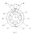
- FIG.3 and FIG.4 show, at the two ends of the insulating halves, two outer 10 and two inner support half rings 11 used from stable plates. made from pressed silicate fibers consist. This material is particularly characterized by its high mechanical strength and due to its good thermal properties from the outer support half rings also serve as fixed attachment points for the outer skin 5 and the inner support half rings 11 are used for fastening the inner skin 7.
- the attachment of the Glass fiber materials on the support half rings are made with steel clips, which are brought into the air pressure Plates are shot.
- the outer 10 and inner support rings 11 themselves are in Envelopes 9 introduced to hold them in place.
- the rest of the inner skin 7 of the exhaust part 3 and the cylinder outlet 4 is fitted with a contour adapted V4A wire mesh 13 protected by its good elastic and mechanical Features.
- the wire mesh 13 is fastened by means of Steel clips on the outer 10 and inner support half rings 11, using glass fiber thread on the inner skin 7, preferably along the edges, in particular along the Boundaries without support half rings, and by means of roller welding on the chrome steel sheet 12.
- the insulating material 14 is required to be caused by the engine vibrations is not affected and that it is not affected by hot Can ignite engine oil itself.
- the resistance to engine vibrations is indicated by a Long-fiber insulating material 14 reached.
- the second requirement for insulation 14 can can only be achieved by a material that is not in the case of hot engine oil behaves catalytically. These requirements are met, for example, by silicate fiber mats Fulfills.
- Velcro fastener 16 In order to be able to connect the two insulating halves 1 and 2 and around the insulating halves to be able to connect with the possibly adjacent insulation components on the two joints and on the front sides of the insulating halves 1 and 2, as well as on the A flap 15 made of glass fiber material with two-sided Sewn on silicone coating, on the inside of each a Velcro fastener 16 is attached. These Velcro fasteners 16 are urgently needed to to be able to withstand the high temperatures to which they are exposed in the event of possible gap losses are. As test bench tests have shown, other types of closures either due to the high temperatures resulting from gap losses or the mechanical Vibrations caused by the motor excitations are destroyed. With this connecting tab 15 gap losses can be significantly reduced.
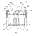
- the exhaust pipes have metal expansion joints 17, which have the task of absorbing the axial longitudinal strains caused by the high exhaust gas temperatures.
- These compensators are connected on the left and right by screwed flanges to the exhaust parts 3, in particular those with integrated cylinder outlets 4. So that the insulating halves 1 and 2 cannot be destroyed by these longitudinal changes, the insulation in the area of the metal compensator 17 must be elastic. This is done by two insulating halves 18 and 19. Each insulating half 18, 19 has an outer skin 20 consisting of a glass fiber material with a two-sided silicone coating.
- a bellows 21 is sewn in, which is made of a glass fabric with a two-sided silicone coating.
- the silicone coating is necessary to prevent hot engine oil from penetrating the insulation. So that the bellows 21 can absorb the longitudinal expansions of the exhaust line, the outer skin 20 of the adjacent cylindrical parts must counteract the longitudinal forces with a certain resistance. This is achieved in that the silicone coating of the outer skin 20 has a weight of at least 400 g / m 2 and that of the bellows has a weight of at most 145 g / m 2 .
- each insulating half 18, 19 ends approximately 40 mm before the ends of the circumference. This means that on the two long sides of the insulating halves 18, 19 in the area of the bellows 21 there are two wrinkle-free strips 22 of approximately 40 mm in width. The bellows 21 is guided under these strips 22 at both ends and sewn together.
- the inner bellows 28 is preferably also distinguished in that it ends in front of the sealing surfaces 25.
- One insulating half 18 is provided with tabs 23. to which a metal Velcro tape 24 is sewn. These Velcro fasteners are used to fasten the insulating halves 18 and 19 to one another.
- the flaps 23 are made of glass fiber fabric with a double-sided silicone coating, the silicone coating must have a minimum weight of approx. 400 gr / m 2 .
- flat sealing surfaces 25 of the butt joints are required.
- the sealing surface 25 is also formed between the smooth Velcro area and the area of the inner bellows 28 not as a bellows, but as a flat surface in order to keep the gap losses as low as possible and to prevent the destruction of the outer shell 20 by the high exhaust gas temperatures.
- the insulating halves 18, 19 are pretensioned or assembled somewhat compressed and can extend to the length of the sealing surface 25. During assembly, the sealing surfaces are slightly bulged or corrugated and are tightly connectable.
- flaps 23 For fastening the insulating halves 18 and 19 to the adjacent insulating halves 1 and 2 flaps 23 with Velcro fasteners 24 on the front ends 26 of the insulating halves 18 and 19 sewn.
- the flaps 23 are made of the same material as that Outer shell 20 made.
- the front ends 26 of the insulating halves 18 and 19, the inner skin 27 or the inner jacket, the inner bellows 28, the sleeves 29 for the support half rings 30 and the sealing surfaces 25 are made of a glass fiber fabric interwoven with V4A wires.
- Support half rings 30 made of stable plates used, the pressed silicate fibers consist. This material is characterized by its high mechanical strength and due to its good thermal properties.
- the outer support half rings serve additionally as fixed attachment points for the outer skin 20 and the inner skin 27.
- the glass fiber materials are attached to the support half-rings 30 using steel clips be shot into the plates using air pressure.
- the support half rings 30 themselves are in Introduced cloth envelopes or wrappings 29 to hold them in position.
- the fabric of the inner bellows 28 is not additionally protected because the bellows has no contact with the metal compensator 17 and about the mobility of the bellows 28 not to interfere. If on both sides of the bellows V4A wire mesh 31 on the inner skin 27 are attached, this increases the rigidity, as is the case with the outer skin 20 is achieved through an increased silicone coating.
- the insulating material 32 is required to be caused by the engine vibrations is not affected and that it is not affected by hot Can ignite engine oil itself. Compensator insulation is further aggravated to the fact that the insulating material 32 in the region of the bellows large changes in length is subject. Resistance to engine vibrations and large changes in length request, in contrast to EP 0 403 943, stipulates the rock wool mats, a long-fiber insulating material. The third requirement for the insulating material can only be met by a material that is not catalytic in the case of hot engine oil behaves. These requirements are met, for example, by silicate fiber mats.
- the layers of the shell elements namely the inner skin, the outer skin, the friction layer and also the layer of insulating material are made from parts of flat material webs manufactured. So it is basically two-dimensional parts that are first by sewing together, in the case of wire mesh by roller welding, or in In case of the insulating material by filling it into the casing, to form a layer three-dimensional shape.
- the flat parts must be selected as cuts so that the layers compiled from it are essentially exactly the same as the Get the component in the correct shape. Because both the fiberglass and the grid flexible or soft, there may be minor deviations from the desired shape can be compensated for by deformations.
- the inner skin and the friction layer lie accordingly essentially completely on the component surface, even if the blanks just two-dimensional approximations to the effective curvatures with any Changes in curvature are.
- the exact or bead-free concern prevents this Development of releasing forces.
- flat ones not on the outer surface of the respective component adapted cushions occur ridges, the forces to the closures with strong vibrations transferred, which are then torn open. It is with the closures It is also important that the connecting forces cannot only be achieved selectively or in sections are.
- the connection must be linear or striped along the whole The edges of the shell elements extend, which is preferred for detachable connections is made possible with Velcro fasteners.
- the minimum deviation criteria must be used a similarity surface can be determined from two-dimensional partial surfaces whose Deviations smaller than the maximum are permitted.
- the outer skin is approximated to a surface that is a desired layer thickness from the outer surface of the component is spaced.
- the blank parts of the layer of insulating material are preferred approximated to a surface that runs between the inner and outer skin.
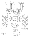
- FIG. 5a and 5b show an example of an inner skin composed of blank parts 40-57 7 of a shell element for a pipe section with a drop.
- the wrappings 9 for the support parts are also shown as an area of the inner skin. That of simple pipe bends known fish-shaped, or symmetrical with respect to two central axes, Cut-out parts are not sufficient to approximate surfaces that are in different Directions are variably curved. As can be seen from the shape of the cut parts 41-43, include shell elements for components with complicated geometries of the outer surfaces symmetry-free cut parts.
Landscapes
- Engineering & Computer Science (AREA)
- General Engineering & Computer Science (AREA)
- Mechanical Engineering (AREA)
- Exhaust Silencers (AREA)
Description
Die Erfindung bezieht sich auf Isolierungen nach dem Oberbegriff des Anspruches 1.
Solche Isolierungen werden zum thermischen und akustischen Isolieren von Maschinen,
Verbrennungsmotoren, insbesondere Turbolader, Auspuffleitungen, Gas- und
Dampfturbinen, Leitungskompensatoren, Behältern, und dgl., an deren Oberfläche erhöhte
Temperaturen und insbesondere mechanischen Schwingungen auftreten und/oder von denen
Geräusche ausgehen, eingesetzt.The invention relates to insulation according to the preamble of
Im speziellen Fall umfasst die Erfindung thermische und akustische Isolierungen für Auspuffleitungen und Turbolader, wie beispielsweise für mittelschnell laufende Dieselmotoren, welche im Falle der Inspektion, Revision und im Havariefall von Hand schnell entfernt und wieder montiert werden können.In a special case, the invention includes thermal and acoustic insulation for exhaust pipes and turbochargers, such as for medium-speed diesel engines, which is quickly removed by hand in the case of inspection, revision and in the event of an accident and can be reassembled.
Die Isolierung von Auspuffleitungen und Turboladern hat die Aufgabe, den Wärmeverlust durch Abstrahlung und Konvektion von den heissen Teilen sowie die Schallübertragung zu reduzieren und gleichzeitig einen Berührungsschutz zu gewährleisten. Dabei ist wichtig, dass eine gleichmässige Temperaturverteilung auf dem Auspuff oder dem Turbolader erzielt wird und somit Wärmespannungen, die Gusskörper zerstören, verhindert werden. Beim Bersten des Turboladers, dessen Schaufelrad mit sehr hoher Geschwindigkeit rotiert, müsste mit sehr schweren Schäden an Leib und Gut gerechnet werden.The insulation of exhaust pipes and turbochargers has the task of heat loss through radiation and convection from the hot parts as well as sound transmission reduce and at the same time ensure protection against contact. It is important that achieve an even temperature distribution on the exhaust or turbocharger and thus thermal stresses that destroy castings can be prevented. At the Bursting of the turbocharger, whose paddle wheel rotates at very high speed, very serious damage to body and property would have to be expected.
Die Dieselmotoren müssen sehr oft gewartet werden. Diese Tatsache bedingt, dass die Isolierung am Auspuff und am Turbolader mit wenig Aufwand von Hand innert kürzerster Zeit demontiert und wieder montiert werden kann.The diesel engines have to be serviced very often. This fact means that the insulation on the exhaust and turbocharger with little effort by hand in a very short time disassembled and reassembled.
Die heutigen Isoliersysteme weisen verschiedene Nachteile auf. Die haufigste Art der Auspuff- und Turboladerisolierung ist die sogenannte Kassettenisolierung. Unter einer Kassette versteht man ein Gehäuse, das aus Stahl- oder Chromstahlblech zusammen geschweisst ist, wobei die Innenseite des Gehäuses keine Abdeckung aufweist. Als Isolierung werden häufig Isolierkissen verwendet, deren Hüllen aus Glasfaserstoff bestehen und mit Isoliermatten gefüllt sind. Die Kissen werden oft durch Schweissnägel im Gehäuse befestigt und zusätzlich durch Querstreben, die auf das Innengehäuse geheftet werden, gehalten. Diese Kassettenisolierungen weisen durch die Schweissnägel und die Querstreben grosse Wärmeleiter auf, welche einerseits zu grossen Wärmeverlusten führen und anderseits die äussere Oberfläche derart aufheizen können, dass kein sogenannter Handschutz mehr gegeben ist (d.h. die Oberflächentemperatur ist grösser als 70°C). Diese metallischen Haltekonstruktionen sind auch grosse sogenannte Schallbrücken, die für die unerwünschte Schallübertragung nach aussen sehr förderlich sind.Today's insulation systems have various disadvantages. The most common type of exhaust and turbocharger insulation is the so-called cassette insulation. Under a cassette is a housing that is welded together from steel or chrome steel sheet is, wherein the inside of the housing has no cover. As insulation insulation cushions are often used, the covers of which are made of fiberglass and with insulation mats are filled. The pillows are often attached to the case by welding nails and additionally held by cross struts that are attached to the inner housing. This Cassette insulation has large heat conductors due to the welding nails and the cross struts which lead to large heat losses on the one hand and the can heat up the outer surface so that there is no longer a so-called hand protection (i.e. the surface temperature is greater than 70 ° C). These metallic support structures are also large so-called sound bridges, which are for the unwanted Sound transmission to the outside are very beneficial.
Der wichtigste Nachteil der heutigen Kassettenisoliersysteme ist aber die Tatsache, dass die Isolierung nicht direkt auf dem Auspuff aufliegen darf, da sonst die Kissen in den Kassetten durch die grossen Relativ-Bewegungen, die durch die Motorschwingungen zwischen Auspuff und Isolierung entstehen, nach kurzer Zeit zerstört werden. Um dies zu verhindern, ist man gezwungen, die Isolierkassetten von der Auspuffleitung schwingungsmässig zu entkoppeln. Dies geschieht dadurch, dass durch eine separate, aufwendige Stützkonstruktion die Kassetten in einem gewissen Abstand zur Auspuffleitung in Position gehalten werden. Diese Stützkonstruktion weist ebenfalls schlechte wärmetechnische und schalltechnische Eigenschaften auf. Eine solche Haltekonstruktion verursacht zudem unnötige Zusatzkosten, grosse Dimensionen der Kassetten, Unhandlichkeit und grosse Gewichte. Die Kassetten können zudem nur mit einem Kran demontiert und wieder montiert werden.The main disadvantage of today's cassette insulation systems is the fact that the insulation must not lie directly on the exhaust, otherwise the pillows in the cassettes through the large relative movements caused by the motor vibrations between Exhaust and insulation arise, can be destroyed after a short time. To prevent this, one is forced to vibrate the isolation cassettes from the exhaust pipe decouple. This happens because of a separate, expensive Support the cassettes in position at a certain distance from the exhaust pipe being held. This support structure also has poor thermal and acoustic properties. Such a support structure also causes unnecessary Additional costs, large dimensions of the cassettes, unwieldiness and large weights. The cassettes can also only be dismantled and reassembled with a crane become.
In der EP 0 403 943 B1 wird eine thermische Isolierung für Rohr!eitungskompensatoren beschrieben, bestehend aus zwei Halbschalen, wobei jede Halbschale eine aus Glasgewebe mit aufgedämpfter Aluminiumfolie bestehende Aussenhülle mit integriertem Balg und eine aus Glasgewebe bestehende Innenhülle mit integriertem Balg aufweist. Die Stirnseiten werden mit formstabilen Halbringen ausgekleidet. Als Isoliermaterial werden Steinwollmatten verwendet. Die zwei Isolierhälften werden mittels temperaturbeständigen Reissverschlüssen zusammengehalten. Die Funktionsweise der Isolierung ist folgendermassen: Der Isolierkörper wird bei der Montage zwischen die Enden der anschliessenden Festisolierung (Blechabschlüsse) der Rohrleitung geklemmt. Durch Zusammendrücken des Balges bei der Montage ensteht eine Federwirkung, sodass auf diese Weise die Stirnseiten des Isolierkörpers zwangsläufig allen axialen und angularen Bewegungen aufgrund von thermisch verursachten Längenänderungen folgen. Versuche haben gezeigt, dass der Glasfaserstoff, der mit V4A-Drähten durchwoben ist, den Relativbewegungen, die bei den mechanischen Schwingungen entstehen nicht widerstehen kann und dass es unweigerlich zur Zerstörung des Stoffes kommt. Weiter haben sich die Stoffe mit aufgedämpfter Aluminiumfolie als Aussenhülle, nicht bewährt, da die Aluminiumfolie durch Strahlungstemperaturen am Motor oder durch Spaltverluste des Isolierkörpers zerstört wird und somit sowohl die Funktionsweise der Isolierung als auch der Schutz gegen das Eindringen von heissem Motorenöl nicht mehr gegeben sind. Weiter hat sich gezeigt, dass sich die Reissverschlüsse, die die zwei Isolierhälften zusammenhalten, nach einer gewissen Betriebszeit nicht mehr öffnen lassen. Steinwollmatten als Isoliermaterial ist für Körper, die mechanischen Schwingungen unterworfen sind, völlig ungeeignet, da sich Steinwollmatten aufgrund der Schwingungen mit der Zeit in Staub auflösen.EP 0 403 943 B1 describes thermal insulation for pipe expansion joints described, consisting of two half-shells, each half-shell one made of glass fabric with a dampened aluminum foil existing outer shell with integrated bellows and has an inner shell made of glass fabric with an integrated bellows. The end faces are lined with dimensionally stable half rings. Rock wool mats are used as insulation material used. The two insulating halves are made using temperature-resistant zippers held together. The insulation works as follows: The Insulator is installed between the ends of the subsequent fixed insulation (Sheet metal ends) of the pipeline clamped. By squeezing the bellows at the Installation creates a spring effect, so that the end faces of the insulating body inevitably all axial and angular movements due to thermally induced Changes in length follow. Experiments have shown that the fiberglass, the is woven with V4A wires, the relative movements that occur with the mechanical Vibrations cannot arise and that it is inevitable to destruction of the substance is coming. Furthermore, the fabrics with dampened aluminum foil as the outer shell, not proven because the aluminum foil due to radiation temperatures on the engine or is destroyed by gap losses of the insulating body and thus both the functionality insulation as well as protection against the penetration of hot engine oil are no longer given. It has also been shown that the zippers that the Hold two insulation halves together, do not open them after a certain operating time to let. Rock wool mats as insulation material is for body, the mechanical vibrations are completely unsuitable because rock wool mats due to the vibrations dissolve in dust over time.
Der vorliegenden Erfindung liegt daher die Aufgabe zugrunde, ein flexibles Isoliersystem zu schaffen, das gute thermische und akustische Isolationseigenschaften hat, einfach montierbar und entfernbar ist und zudem auch bei hohen Temperaturen und starken Schwingungen des zu isolierenden Bauteils eine hohe Lebensdauer hat.The present invention is therefore based on the object of providing a flexible insulation system create that has good thermal and acoustic insulation properties, easy to install and is removable and also at high temperatures and strong vibrations of the component to be insulated has a long service life.
Diese Aufgabe wird durch die Merkmale des Anspruches 1
gelöst. Die abhängigen Ansprüche beschreiben bevorzugte Ausführungsformen.This object is achieved by the features of
Beim Lösen der Aufgabe wurde erkannt, dass die Isolierung so ausgeführt werden muss, dass keine isolationsfreien Verbindungen von Bauteil-Aussenbereichen zur Aussenseite der Isolierung führen. Dies kann am besten dadurch erzielt werden, dass die miteinander verbindbaren Schalenelemente bzw die Hüllen mit dem Isoliermaterial an die jeweilige Form der Aussenfläche des Bauteils angepasst sind und mit einer Kontaktfläche im wesentlichen dicht an der Aussenfläche des Bauteiles anliegen. Durch das Aneinanderanliegen entstehen aufgrund der Schwingungen bzw. Vibrationen des Bauteils hohe Reibungskräfte, vor deren zerstörenden Wirkung die Hülle bei der erfindungsgemässen Lösung durch das Einsetzen einer reibungsaufnehmenden Kontakt- bzw. Reibungsschicht geschützt wird. Die Reibungsschicht ist an die Form des Bauteiles angepasst und nimmt die schwingungsbedingte Reibung zwischen dem Bauteil und dem Schalenelement flächig auf Lediglich im Bereich von Kompensatoren, bzw. deren Balgelemente ist ein Anliegen der Schalenelemente nicht erwünscht, weil die Funktionsfähigkeit von Balgelementen durch anliegendes, bzw. eingeklemmtes Isolationsmaterial bzw. Hüllenbereiche eingeschränkt und gleichzeitig die Isolation zerstört wird. Daher muss im Bereich der Kompensatoren ein dichtes Aneinanderanschliessen der miteinander verbundenen, vom Kompensator beabstandeten Schalenelemente gewährleistet werden, so dass der Freiraum zwischen dem Bauteil und der Isolierung nach aussen dicht abgeschlossen ist. Dies wird durch das Verzichten auf balgförmige Dichtflächen zwischen den miteinander verbundenen Schalenelementen erzielt, wobei auf den Balg lediglich im Bereich der Dichtflächen verzichtet wird, so dass aufgrund der zentralen Balgbereiche der Verformungsbereich genügend klar ausgebildet ist um die Dehnungs- und Schrumpfungsbewegungen aufzunehmen. Unerwünschte Verformungen mit der Gefahr eines Kontaktes zwischen der Isolierung und dem Kompensatorbalg treten nicht auf. Von den zentralen Balgbereichen geht gegebenenfalls eine Federwirkung aus, die insbesondere bei zusammengepresst montierten Schalenelementen gewährleistet, dass diese den Dehnungen ohne das Anwenden von Zugkräften folgen können.When the task was solved, it was recognized that the insulation must be carried out in such a way that there are no insulation-free connections from component outer areas to the outside of the Lead insulation. The best way to achieve this is by connecting the interconnectable ones Shell elements or the sleeves with the insulating material to the respective Shape of the outer surface of the component are adapted and with a contact surface essentially lie close to the outer surface of the component. By being close to each other arise due to the oscillations or vibrations of the component high Frictional forces, before the destructive effect of the shell in the inventive Solution by inserting a friction-absorbing contact or friction layer is protected. The friction layer is adapted to the shape of the component and takes the vibration-related friction between the component and the shell element flat on only in the area of expansion joints or their bellows elements a concern of the shell elements is not desirable because of the functionality of bellows elements through adjacent or clamped insulation material or envelope areas and at the same time the insulation is destroyed. Therefore in the area of the expansion joints must be a tight connection of the connected, spaced from the compensator shell elements guaranteed be so that the space between the component and the insulation after is tightly sealed on the outside. This is achieved by dispensing with bellows-shaped sealing surfaces achieved between the interconnected shell elements, being on the bellows is dispensed with only in the area of the sealing surfaces, so that due to the central bellows areas the deformation area is sufficiently clear around the Absorbing stretching and shrinking movements. Undesirable deformations with the risk of contact between the insulation and the compensator bellows do not occur. A spring action may be exerted from the central bellows areas which ensures, in particular, when the shell elements are pressed together, that they follow the stretches without applying tensile forces can.
Das Isoliersystem ist leicht demontierbar und wieder montierbar und wie bei herkömmlichen Isolierkissen ist sein eigentlicher Isolierkörper weich, um die Form der Isolierung dem zu isolierenden Körper anpassen zu können. Wobei darauf zu achten ist, dass Rohrabzweiger direkt in der Isolierkomponente integriert werden, um eine homogene Isolierkomponente zu erhalten. Das Isoliersystem ist trotz weichem Isolierkörper formstabil. Dort wo extreme Längenänderungen infolge von hohen Temperaturen (z.B. bei Auspuffleitungen) durch Metallkompensatoren kompensiert werden, ist die Isolierkomponente im Bereich des Kompensators flexibel ausgeführt, so dass das Isoliersystem die Bewegungen der Auspuffleitung mitmacht. Ansonsten könnte das Isoliersystem selbst und/oder der Kompensator zerstört werden. Die innere Fläche des Isoliersystems, die auf dem zu isolierenden Körper zu liegen kommt, ist resistent gegen Relativ-Bewegunge, die durch mechanische Schwingungen hervorgerufen werden. Das Hüllenmaterial des Isoliersystems ist vorzugsweise durch eine zumindest einseiteige, insbesondere aber beidseitige Silikonbeschichtung gegen das Eindringen von heissem Motorenöl geschützt.The insulation system is easy to dismantle and reassemble and as with conventional ones Insulating cushion, its actual insulating body is soft to match the shape of the insulation to be able to adapt the insulating body. Care should be taken that the pipe branch can be integrated directly into the insulation component to create a homogeneous insulation component receive. The insulation system is dimensionally stable despite the soft insulating body. Where extreme Changes in length due to high temperatures (e.g. with exhaust pipes) due to metal expansion joints to be compensated for is the insulating component in the area of the compensator flexibly designed so that the insulation system the movements of the exhaust pipe participates. Otherwise the insulation system itself and / or the compensator could be destroyed become. The inner surface of the insulation system that lie on the body to be insulated is resistant to relative movements caused by mechanical vibrations become. The casing material of the insulation system is preferably at least one one-sided, but especially two-sided silicone coating to prevent penetration protected by hot engine oil.
Die Zeichnungen erläutert die erfindungsgemasse Isolierung anhand zweier Ausführungsbeispiele. Dabei zeigt
- Fig 1
- eine stirnseitige Ansicht eines mit einer zweiteiligen Isolierung isolierten Rohrabschnittes mit einem Abgang
- Fig. 2
- im oberen Bereich eine Schnittdarstellung gemäss A-A und im unteren Bereich eine Seitenansicht des Rohrabschnittes mit Abgang gemäss Fig. 1
- Fig. 3
- eine stirnseitige Ansicht eines mit einer zweiteiligen Isolierung isolierten Metallkompensators
- Fig. 4
- im oberen Bereich eine Schnittdarstellung gemäss B-B und im unteren Bereich eine Seitenansicht des Kompensators gemäss Fig. 3
- Fig. 5a
- eine perspektivischen Darstellung der Innenhaut eines Schalenelementes
- Fig. 5b
- eine Zusammenstellung von Zuschnitt-Teilen der Innenhaut gemäss Fig. 5a
- Fig. 1
- an end view of a pipe section isolated with a two-part insulation with an outlet
- Fig. 2
- in the upper area a sectional view according to AA and in the lower area a side view of the pipe section with outlet according to FIG. 1
- Fig. 3
- an end view of a metal compensator insulated with two-part insulation
- Fig. 4
- in the upper area a sectional view according to BB and in the lower area a side view of the compensator according to FIG. 3
- Fig. 5a
- a perspective view of the inner skin of a shell element
- Fig. 5b
- a compilation of cut parts of the inner skin according to FIG. 5a
Die Zeichnungen FIG.1 und FIG.2 zeigen die zwei zusammengefügten Isolierhälften 1 und 2
für einen Auspuffteil 3 mit integriertem Zylinderabgang 4. Jede Isolierhälfte besitzt eine
Aussenhaut 5 bestehend aus einem Glasfaserstoff mit zweiseitiger Silikonbeschichtung, die
das Eindringen von Öl und Spritzwasser verhindert. Der Hüllenbereich der Stirnseiten 6 der
Isolierhälften besteht aus einem mit V4A-Drähten durchwobenem Glasfasergewebe. Die
V4A-Drähte verleihen dem Glasgewebe eine erhöhte mechanische Festigkeit bei hohen
Einsatztemperaturen. Die Innenhaut 7, bzw. der Innenmantel der Isolierkomponenten ist so
ausgebildet, dass er exakt den äusseren Konturen des Auspuffteils 3 und dem Zylinderabgang
4 folgt, um eine möglichst gleichmässige Wärmeverteilung auf dem Gusskörper zu
erhalten und um Wärmespannungen im Guss zu vermeiden, die zu Wärmerissen führen
könnten. Weiter werden Wärmezirkulationen zwischen dem Gusskörper und der Isolierung
vermieden, welche erhöhte Temperaturverluste zur Folge hätten. Die Kontur der Aussenhaut
5 verläuft parallel zu der Kontur der Innenhaut 7, im Abstand der entsprechenden Isolierstärken.
Die Innenhaut 7, die Fugenflächen 8 und die Umhüllungen 9 für die äusseren 10
und die inneren Stützhalbringe 11 sind aus dem V4A-Drähten verstärktem Glasfasergewebe
gefertigt.The drawings FIG. 1 and FIG. 2 show the two insulating
Um eine Stabilität der Isolierhälften zu erreichen und um beispielsweise eventuelle Axialkräfte
aufnehmen zu können, die an den beiden Stirnflächen durch benachbarte Kompensatoren
entstehen. die als Isolierkomponenten ausgebildet sind, wie Zeichnungen FIG.3 und
FIG.4 zeigen, werden bei den zwei Enden der Isolierhälften je zwei äussere 10 und je zwei
innere Stützhalbringe 11 aus stabilen Platten verwendet. die aus gepressten Silikatfasern
bestehen. Dieses Material zeichnet sich vorallem durch seine hohe mechanische Festigkeit
und durch seine guten wärmetechnischen Eigenschaften aus Die äusseren Stützhalbringe
dienen zusätzlich als fixe Befestigungspunkte fur die Aussenhaut 5 und die inneren Stützhalbringe
11 werden zur Befestigung der Innenhaut 7 verwendet. Die Befestigung der
Glasfaserstoffe auf die Stützhalbringe erfolgt mit Stahlklammern, die mittels Luftdruck in die
Platten geschossen werden. Die äusseren 10 und inneren Stützringe 11 selber werden in
Umhüllungen 9 eingebracht, um sie in Position zu halten.To achieve stability of the insulating halves and, for example, possible axial forces
to be able to accommodate the two end faces by adjacent compensators
arise. which are designed as insulating components, such as drawings FIG.3 and
FIG.4 show, at the two ends of the insulating halves, two outer 10 and two
inner support half rings 11 used from stable plates. made from pressed silicate fibers
consist. This material is particularly characterized by its high mechanical strength
and due to its good thermal properties from the outer support half rings
also serve as fixed attachment points for the
Die Aussenseite der Innenhaut 7 der Isolierhälften 1 und 2, wo die Isolierhälften den Gusskörper
3 und 4 des Auspuffs berühren, muss zusätzlich geschützt werden, da durch die
Motorschwingungen hohe Relativ-Bewegungen zwischen dem Gusskörper 3 und 4 des
Auspuffs und der Innenhaut 7 entstehen. Tests auf dem Motorenprüfstand haben gezeigt,
dass die Relativ-Bewegungen den Glasfaserstoff zerstören, obwohl er zur mechanischen
Verstärkung mit V4A-Drähten durchwoben ist. Zum Schutz der Innenhaut 7 der Isolierhälften
1 und 2 , der auf dem Auspuffteil 3 aufliegt, werden im Bereich zwischen den zwei inneren
Stützhalbringen 11 je ein Chromstahlblech 12 angebracht. Das Chromstahlblech 12 wird
an die Kontur des Auspuffteils 3 angepasst. Die Befestigung des Chromstahlbleches erfolgt
mittels Spanplattenschrauben direkt mit den inneren Stützhalbringen 11. Die übrige Innenhaut
7 des Auspuffteils 3 und des Zylinderabgangs 4 wird mit einem, der Kontur angepasstem
V4A-Drahtnetz 13 geschützt, dass sich durch seine guten elastischen und mechanischen
Eigenschaften auszeichnet. Die Befestigung des Drahtnetzes 13 erfolgt mittels
Stahlklammern an den äusseren 10 und inneren Stützhalbringen 11, mittels Glasfaserfaden
an der Innenhaut 7, vorzugsweise entlang der Berandungen insbesondere entlang der
Berandungen ohne Stützhalbringe, und mittels Rollenschweissen am Chromstahlblech 12.The outside of the
Bei der Auspuffisolierung wird vom Isoliermaterial 14 verlangt, dass es durch die Motorschwingungen
nicht in Mitleidenschaft gezogen wird und dass es sich nicht durch heisses
Motorenöl selbst entzünden kann. Die Resistenz gegen Motorschwingungen wird durch ein
langfaseriges Isoliermaterial 14 erreicht. Die zweite Anforderung an die Isolierung 14 kann
nur von einem Material erreicht werden, das sich im Falle von heissem Motorenöl nicht
katalytisch verhält. Diese Anforderungen werden beispielweise durch Silikatfasermatten
erfüllt.In the case of exhaust insulation, the insulating
Um die beiden Isolierhälften 1 und 2 miteinander verbinden zu können und um die Isolierhälften
mit den eventuell benachbarten Isolierkomponenten verbinden zu können, werden
an die zwei Trennungsfugen und an die Stirnseiten der Isolierhälften 1 und 2, sowie an die
Stirnseite des integrierten Zylinderabganges je ein Lappen 15 aus Glasfaserstoff mit zweiseitiger
Silikonbeschichtung angenäht, auf deren Innenseiten je ein Metallklettenverschluss
16 angebracht wird. Diese Metallklettenverschlüsse 16 sind dringendst erforderlich, um den
hohen Temperaturen widerstehen zu können, denen sie bei möglichen Spaltverlusten ausgesetzt
sind. Wie Prüfstandstest gezeigt haben, werden andere Verschlussarten entweder
durch die hohen Temperaturen, die von Spaltverlusten herrühren, oder durch die mechanischen
Schwingungen, die durch die Motorerregungen hervorgerufen werden, zerstört. Mit
diesen Verbindungslappen 15 können Spaltverluste erheblich reduziert werden.In order to be able to connect the two insulating
Ein weiteres Ausführungsbeispiel wird anhand der Zeichnungen FIG.3 und FIG.4 näher beschrieben.
Meistens besitzen die Auspuffrohre Metallkompensatoren 17, welche die Aufgabe
haben, die axialen Längsdehnungen aufzunehmen, die durch die hohen Abgastemperaturen
entstehen. Diese Kompensatoren sind links und rechts durch geschraubte Flansche
mit den Auspuffteilen 3, insbesondere solche mit integrierten Zylinderabgängen 4, verbunden.
Damit nun die Isolierhälften 1 und 2 nicht durch diese Längsänderungen zerstört werden
können, muss die Isolierung im Bereich des Metallkompensators 17 elastisch ausgeführt
sein. Dies geschieht durch zwei Isolierhälften 18 und 19. Jede Isolierhälfte 18, 19
besitzt eine Aussenhaut 20 bestehend aus einem Glasfaserstoff mit zweiseitiger Silikonbeschichtung.
Im mittleren Bereich der beiden Isolierhälften 18, 19 ist ein Balg 21 eingenäht,
der aus einem Glasgewebe mit zweiseitiger Silikonbeschichtung gefertigt ist. Die Silikonbeschichtung
ist notwendig, um ein Eindringen von heissem Motorenöl in die Isolierung zu
verhindern. Damit der Balg 21 die Längsdehnungen der Auspuffleitung aufnehmen kann,
muss die Aussenhaut 20 der angrenzenden zylindrischen Teile mit einem gewissen Widerstand
den Längskräften entgegenwirken. Dies wird dadurch erreicht, dass die Silikonbeschichtung
der Aussenhaut 20 ein Gewicht von mindestens 400 g/m2 und die des Balges
ein solches von maximal 145 g/m2 aufweist.Another embodiment is described in more detail with reference to the drawings FIG.3 and FIG.4. Most of the time, the exhaust pipes have
Im Gegensatz zur EP 0 403 943 B1 endet zumindest der äussere Balg 21 jeder Isolierhälfte
18, 19 ca. 40 mm vor den Enden des Umfanges. Das heisst, auf den beiden Längsseiten
der Isolierhälften 18, 19 im Bereich des Balges 21 sind je zwei faltenlose Streifen 22 von ca.
40 mm Breite vorhanden. Der Balg 21 wird an beiden Enden unter diese Streifen 22 geführt
und zusammengenäht. Vorzugsweise zeichnet sich auch der inneren Balg 28 dadurch aus,
dass er vor den Dichtflächen 25 endet. Die eine Isolierhälfte 18 wird mit Lappen 23
versehen. auf die je ein Metallklettenband 24 genaht ist Diese Klettverschlüsse dienen zur
Befestigung der Isolierhälften 18 und 19 untereinander. wobei jeweils das am Lappen 23
befestigte Metallklettband 24 mit einem auf der Aussenhaut der anderen Isolierhälfte befestigten
Metallklettband zusammenwirkt und die beiden Isolierhälften 18, 19 seitlich gestossen
zusammenhält. Die Lappen 23 werden aus Glasfasergewebe mit zweiseitiger
Silikonbeschichtung gefertigt, wobei die Silikonbeschichtung ein Mindestgewicht von ca. 400
gr/m2 aufweisen muss. Damit möglichst keine Heissgase austreten können,die zur
Zerstörung der Aussenhülle und der Klettverschlüsse führen, sind ebene Dichtflächen 25
der Stossstellen erforderlich. Die Erfahrung hat gezeigt, dass bei der EP 0 403 943 B1 die
Verschlusslappen, die als Bälge ausgebildet sind, bei hohen Abgastemperaturen verkohlen
Das ist der Grund, dass der Balg 21 an diesen Stellen erfindungsgemäss durch faltenlose
Streifen 22 ersetzt wird. Die Dichtfläche 25 wird auch zwischen dem glatten Klettbereich
und dem Bereich des inneren Balges 28 nicht als Balg, sondern als ebene Fläche
ausgebildet, um die Spaltverluste so gering wie möglich zu halten und um der Zerstörung
der Aussenhülle 20 durch die hohen Abgastemperaturen vorzubeugen. Die Isolierhälften 18.
19 werden vorgespannt, bzw. etwas zusammengepresst montiert und können sich auf die
Länge der Dichtfläche 25 ausdehnen. Bei der Montage sind die Dichtflächen aneinander
anliegend etwas gebaucht, bzw. gewellt und dabei dicht verbindbar.In contrast to EP 0 403 943 B1, at least the outer bellows 21 of each insulating
Für die Befestigung der Isolierhälften 18 und 19 an die benachbarten Isolierhälften 1 und 2
werden Lappen 23 mit Metallklettenverschlüssen 24 an den stirnseitigen Enden 26 der Isolierhälften
18 und 19 genäht. Die Lappen 23 sind aus dem gleichen Material wie die
Aussenhülle 20 gefertigt.For fastening the insulating
Die stirnseitigen Enden 26 der Isolierhälften 18 und 19, die Innenhaut 27, bzw. der Innenmantel,
der innere Balg 28, die Hüllen 29 für die Stützhalbringe 30 und die Dichtfläcnen 25
sind aus einem mit V4A-Drähten durchwobenen Glasfasergewebe gefertigt.The front ends 26 of the insulating
Um die Stabilität der Isolierhälften 18 und 19 zu erreichen und um die Axialkräfte, die durch
den Balg auf die Stirnflächen wirken, aufnehmen, respektive auf die benachbarten Isolierhälften
1 und 2 an beiden Enden übertragen zu können, werden für die Stirnseiten der Isolierhälften
Stützhalbringe 30 aus stabilen Platten verwendet, die aus gepressten Silikatfasern
bestehen. Dieses Material zeichnet sich durch seine hohe mechanische Festigkeit und
durch seine guten wärmetechnischen Eigenschaften aus. Die äusseren Stützhalbringe dienen
zusätzlich als fixe Befestigungspunkte für die Aussenhaut 20 und die Innenhaut 27. Die
Befestigung der Glasfaserstoffe auf die Stutzhalbringe 30 erfolgt mit Stahlklammern, die
mittels Luftdruck in die Platten geschossen werden. Die Stützhalbringe 30 selber werden in
Stoffhüllen, bzw. Umhüllungen 29 eingebracht, um sie in Position zu halten.To achieve the stability of the insulating
Im Gegensatz zur EP 0 403 943 B1 werden erfindungsgemäss die Aussenseite der Innenhaut
27 der Isolierhälften 18 und 19, wo die Isolierhälften auf den Flanschen des Metallkompensators
17 aufliegen und der Stoff aussen an den Stirnseiten, die gegen die benachbarten
Isolierhälften 1 und 2 drücken, um die Axialkräfte zu übertragen, zusätzlich geschützt,
da durch die Motorschwingungen hohe Relativ-Bewegungen sowohl zwischen den
Flanschen des Metallkompensators 17 und der Innenhaut 27 als auch zwischen den Kontaktflächen
der Stirnseiten der Isolierhälften 18, 19 entstehen. Tests auf dem Motorenprüfstand
haben gezeigt, dass die Relativ-Bewegungen den Glasfaserstoff zerstören, obwohl
er zur mechanischen Verstärkung mit V4A-Drähten durchwoben ist. Um den Glasfaserstoff
zu schützen, werden V4A-Drahtnetze 31 auf die Stoffe an den oben erwähnten
Stellen genäht. Der Stoff des inneren Balges 28 wird nicht zusätzlich geschützt, da der Balg
keinen Kontakt mit dem Metallkompensator 17 hat und um die Beweglichkeit des Balges 28
nicht zu beeinträchtigen. Wenn beidseits des Balges V4A-Drahtnetze 31 an der Innenhaut
27 befestigt sind, so wird dadurch die Steifigkeit erhöht, wie dies bei der Aussenhaut 20
durch eine erhöhte Silikonbeschichtung erzielt wird.In contrast to EP 0 403 943 B1, according to the invention the outside of the
Bei der Auspuffisolierung wird vom Isoliermaterial 32 verlangt, dass es durch die Motorschwingungen
nicht in Mitleidenschaft gezogen wird und dass es sich nicht durch heisses
Motorenöl selbst entzünden kann. Für eine Kompensatorenisolierung kommt weiter erschwerend
dazu, dass das Isoliermaterial 32 im Bereiche des Balges grossen Längenänderungen
unterworfen ist. Die Resistenz gegen Motorschwingungen und die grossen Längenänderungen
verlangen, im Gegensatz zur EP 0 403 943 die Steinwollmatten vorschreibt,
ein langfaseriges Isoliermaterial. Die dritte Anforderung an das Isoliermaterial kann nur von
einem Material erreicht werden, dass sich im Falle von heissem Motorenöl nicht katalytisch
verhält. Diese Anforderungen werden beispielweise durch Silikatfasermatten erfüllt.In the case of exhaust insulation, the insulating
Die Schichten der Schalenelemente, nämlich die Innenhaut, die Aussenhaut, die Reibungsschicht und auch die Schicht aus Isoliermaterial, sind aus Teilen von flächigen Materialbahnen hergestellt. Es handelt sich also grundsätzlich um zweidimensionale Teile, die erst durch das Zusammennähen, im Falle des Drahtgitters durch Rollenschweissen, oder im Falle des Isoliermateriales durch das gestossene Einfüllen in die Hülle, zu einer Schicht mit dreidimensionaler Form führen. Die flächigen Teile müssen als Zuschnitte so gewählt werden, dass die daraus zusammengestellten Schichten eine im wesentlichen exakt an das Bauteil angepasste Form erhalten. Da sowohl der Glasfaserstoff als auch das Gitternetz beweglich, bzw. weich sind, können kleinere Abweichungen von der gewünschten Form durch Verformungen kompensiert werden. Entsprechend liegt die Innenhaut und die Reibungsschicht im wesentlichen vollständig auf der Bauteiloberfläche auf, auch wenn die Zuschnitte lediglich zweidimensionale Annäherungen an die effektiven Krümmungen mit beliebigen Krümmungsänderungen sind. Das genaue bzw. wulstfreie Anliegen verhindert das Entstehen von lösenden Kräften. Bei flachen nicht an die Aussenfläche des jeweiligen Bauteiles angepassten Kissen treten Wülste auf, die bei starken Vibrationen Kräfte zu den Verschlüssen übertragen, welche dann aufgerissen werden. Bei den Verschlüssen ist es ebenfalls wichtig, dass die Verbindungskräfte nicht nur punktuell, oder abschnittweise erzielbar sind. Die Verbindung muss sich linienförmig, bzw. streifenförmig entlang der gesamten Berandung der Schalenelemente erstrecken, was bei lösbaren Verbindungen vorzugsweise mit Klettverschlüssen ermöglicht wird.The layers of the shell elements, namely the inner skin, the outer skin, the friction layer and also the layer of insulating material are made from parts of flat material webs manufactured. So it is basically two-dimensional parts that are first by sewing together, in the case of wire mesh by roller welding, or in In case of the insulating material by filling it into the casing, to form a layer three-dimensional shape. The flat parts must be selected as cuts so that the layers compiled from it are essentially exactly the same as the Get the component in the correct shape. Because both the fiberglass and the grid flexible or soft, there may be minor deviations from the desired shape can be compensated for by deformations. The inner skin and the friction layer lie accordingly essentially completely on the component surface, even if the blanks just two-dimensional approximations to the effective curvatures with any Changes in curvature are. The exact or bead-free concern prevents this Development of releasing forces. In the case of flat ones, not on the outer surface of the respective component adapted cushions occur ridges, the forces to the closures with strong vibrations transferred, which are then torn open. It is with the closures It is also important that the connecting forces cannot only be achieved selectively or in sections are. The connection must be linear or striped along the whole The edges of the shell elements extend, which is preferred for detachable connections is made possible with Velcro fasteners.
Zum Festlegen von zu verwendenden Zuschnitt-Teilen muss nach minimalen Abweichungs-Kriterien eine Ähnlichkeitsfläche aus zweidimensionalen Teilflächen bestimmt werden, deren Abweichungen kleiner als maximal zulässig sind. Für die direkt anliegende Reibungsschicht und die Innenhaut werden ausgehend von der Form der Aussenfläche des Bauteiles zweidimensionale Abwicklungen bzw. Zuschnitt-Teile mit den jeweils benötigten Naht-Zugaben bestimmt, zugeschnitten und zur gewünschten Schicht verbunden. Die Aussenhaut wird an eine Fläche angenähert, die um eine gewünschte Schichtdicke von der Aussenfläche des Bauteils beabstandet ist. Die Zuschnitt-Teile der Schicht aus Isoliermaterial sind vorzugsweise an eine Fläche angenähert, die zwischen der Innen- und der Aussenhaut verläuft.To define the cut parts to be used, the minimum deviation criteria must be used a similarity surface can be determined from two-dimensional partial surfaces whose Deviations smaller than the maximum are permitted. For the direct friction layer and the inner skin are based on the shape of the outer surface of the component two-dimensional developments or cut parts with the required seam allowances determined, cut and connected to the desired layer. The outer skin is approximated to a surface that is a desired layer thickness from the outer surface of the component is spaced. The blank parts of the layer of insulating material are preferred approximated to a surface that runs between the inner and outer skin.
Fig. 5a und 5b zeigen beispielhaft eine aus Zuschnitt-Teilen 40-57 zusammengestellte Innenhaut
7 eines Schalenelementes für ein Rohrstück mit Abzeigung. Die Umhüllungen 9 für
die Stützteile sind ebenfalls als Bereich der Innenhaut dargestellt. Die von einfachen Rohrkrümmungen
bekannten fischförmigen, bzw. bezüglich zweier zentraler Achsen symmetrischen,
Zuschnitt-Teile gnügen nicht um Flächen anzunähern, die in verschiedenen
Richtungen variabel gekrümmt sind. Wie aus der Form der Zuschnitt-Teile 41-43 hervorgeht,
umfassen Schalenelemente für Bauteile mit komplizierten Geometrien der Aussenflächen
symmetriefreie Zuschnitt-Teile.5a and 5b show an example of an inner skin composed of blank parts 40-57
7 of a shell element for a pipe section with a drop. The
Weil die Reibungsschicht direkt an die Innenhaut 7 anschliesst, sind deren Zuschnitt-Teile
im wesentlichen gleich, wie die dargestellten Teile der Innenhaut 7. Gegebenenfalls ist der
teilrohrförmige Zuschnitt 40 bei der Reibungsschicht aus Chromstahlblech und die Zuschnitt-Teile
41-47 aus Drahtgitternetz gebildet.Because the friction layer directly adjoins the
Claims (10)
- Insulation for the external faces of component parts, assembled from shell elements (1,2;18,19) which can be joined to each other and which comprise a cladding of glass fibre material having an inner and an outer skin (7,5;27,20), insulating material (14,32) in the form of layers in the cladding, and rib-like, dimensionally stable supporting parts (10,11;30) which are joined to the cladding and which are disposed at least at two lateral edges, characterised in that the shell elements (1,2;18,19) comprise, at least regionally on the component part side, a friction-absorbing friction layer (12,13) made of sheet-like material which adjoins the inner skin (7), wherein the friction layer is seated against installed shell elements (1,2;18,19) at plain regions of the outer face of the component part and thus absorbs, over its surface, friction between the component part and the shell element (1,2;18,19) which is caused by vibrations.
- Insulation according to claim 1, characterised in that the friction layer (12,13) consists of chrome steel and is preferably constructed regionally as a chrome steel wire mesh, particularly as a V4A wire mesh, or is optionally constructed as a chrome steel sheet, and that wire meshes are preferably fixed by means of steel staples to supporting parts (10,11;30), and are optionally fixed by means of glass fibre threads to the inner skin (7), and in particular are fixed to sheet regions by means of roller welding.
- Insulation according to claims 1 or 2, characterised in that the layer-like insulating material (14,32) is composed of a long-fibre layer material which does not act as a catalyst in contact with hot engine oil, and is preferably composed of parts comprising silicate fibre mats.
- Insulation according to any one of claims 1 to 3, characterised in that the fibreglass material of at least the inner skin (7), and preferably of the entire cladding, is shot through with metal wires, preferably with V4A wires, and/or is coated with silicone on at least one side, preferably on two sides.
- Insulation according to any one of claims 1 to 4, characterised in that the supporting parts (10,11,30) consist of pressed silicate fibre material and/or are surrounded by fibreglass material for stabilising the shell elements (1,2;18,19) and for the transmission of force between shell elements (1,2;18,19) or for the absorption of axial forces, and/or that steel staples are introduced into the supporting parts (10,11,30) through the cladding skin in order to joining the cladding to the supporting parts (10,11,30).
- Insulation according to any one of claims 1 to 5, characterised in that, in order to increase the stability, at least two supporting parts (10,11) at at least one lateral edge are spaced apart from each other parallel to the edge, preferably transversely to the edge, by a cladding region filled with insulating material, wherein, particularly for component parts which comprise regions which project in the manner of flanges from the main face of the component part, an outer supporting part (10) is fitted to the projecting region and an inner supporting part (11) is fitted to the main face.
- Insulation according to any one of claims 1 to 6, characterised in that burred joints comprising burred metal faces (16,24) are provided along the lateral edges, wherein, of each of the burred faces which cooperate in pairs, an outwardly oriented burred face (16) is fixed or is sewn to the outer skin (5) of one shell element (1,2) and an inwardly oriented burred face (24) is fixed or is sewn to a joint tab (23) made of silicone-coated fibreglass material which projects from the other shell element (18,19) beyond the lateral edge, wherein the joint tabs (15,23) are formed from silicone-coated fibreglass material.
- Insulation according to any one of claims 1 to 7, characterised in that the friction layer (12,13), the inner skin (7,27), the outer skin (5,20) and preferably the insulating layer (14,32) also, are assembled from similar blank parts (40-57), wherein the blank parts (40-57) are sized and shaped so that a mounted shell element (1,2;18,19) composed of them runs substantially exactly along an external face, which has any desired shape, of a component part, and the end faces of the lateral edges run substantially normal to the region of the outer face situated beneath them.
- Insulation according to any one of claims 1 to 7, characterised in that the shell elements (18,19) comprise an insulating bellows (21,28) for insulating a compensator (17) which extends along a compensator axis, which insulating bellows, in its installed state, extends beyond part of the periphery of the compensator and extends along the compensator axis substantially beyond the region of a compensator bellows and is spaced radially therefrom, wherein the fold region of the insulating bellows (21,28) is joined or sewn circumferentially on both sides to a fold-free end region, so that circumferentially-adjoining compensator shell elements (18,19) are seated against each other with flat sealing regions (25) and preferably can be joined by burred joints (23,24) which form a continuous closure in an axial direction.
- Insulation according to claim 9, characterised in that along the compensator axis on at least one side, preferably on both sides, of the insulating bellows (21,28) the shell elements (18,19) comprise an unfolded end region which is spaced radially from the compensator (17), the stiffness of which end region is increased by a thicker silicone coating, preferably of at least 400 g/m2, on at least the outer skin (20), optionally on the inner skin (27) also, which increased stiffness thereby ensures that longitudinal expansions do not result in deformations in an end region but are absorbed by the insulating bellows (21,28), wherein the silicone coating on at least the outer skin (20), and optionally also on the inner skin (27) of the insulating bellows (21,28) is preferably less than 145 g/m2.
Applications Claiming Priority (4)
| Application Number | Priority Date | Filing Date | Title |
|---|---|---|---|
| CH154396 | 1996-06-20 | ||
| CH154396 | 1996-06-20 | ||
| CH1543/96 | 1996-06-20 | ||
| PCT/CH1997/000239 WO1997048943A1 (en) | 1996-06-20 | 1997-06-16 | Insulation for structural components having three-dimensional external surfaces |
Publications (2)
| Publication Number | Publication Date |
|---|---|
| EP0906539A1 EP0906539A1 (en) | 1999-04-07 |
| EP0906539B1 true EP0906539B1 (en) | 2000-01-19 |
Family
ID=4212877
Family Applications (1)
| Application Number | Title | Priority Date | Filing Date |
|---|---|---|---|
| EP97924851A Expired - Lifetime EP0906539B1 (en) | 1996-06-20 | 1997-06-16 | Insulation for structural components having three-dimensional external surfaces |
Country Status (4)
| Country | Link |
|---|---|
| EP (1) | EP0906539B1 (en) |
| DE (1) | DE59701049D1 (en) |
| ES (1) | ES2142683T3 (en) |
| WO (1) | WO1997048943A1 (en) |
Families Citing this family (9)
| Publication number | Priority date | Publication date | Assignee | Title |
|---|---|---|---|---|
| AU1544800A (en) | 1998-12-17 | 2000-07-03 | Etis Ag | Soundproofing for insulating sound producing devices or parts of systems, especially devices that transmit vibrations such as vibrators |
| DE10220573C1 (en) | 2002-05-08 | 2003-07-03 | Mtu Friedrichshafen Gmbh | IC engine exhaust gas turbocharger has rupture protection enclosing dangerous section of turbocharger housing |
| DE10254859A1 (en) | 2002-11-25 | 2004-06-03 | Mann + Hummel Gmbh | turbocharger |
| EP1426557B1 (en) * | 2002-12-03 | 2013-07-17 | BorgWarner, Inc. | Casing for turbo charger |
| ATE503958T1 (en) | 2004-02-27 | 2011-04-15 | Etis Ag | INSULATION AND METHOD FOR PRODUCING AN INSULATING ELEMENT |
| EP1737706A1 (en) | 2004-04-21 | 2007-01-03 | Etis AG | Insulation |
| DE202006009673U1 (en) | 2006-06-21 | 2006-08-24 | Etis Ag | Heat and noise insulation jacket for automotive components e.g. catalytic converter or silencer |
| DE102012110707B4 (en) * | 2012-11-08 | 2015-11-19 | Benteler Automobiltechnik Gmbh | Exhaust gas turbocharger assembly with integrated insulating layer |
| DE102017215591A1 (en) * | 2017-09-05 | 2019-03-07 | Man Diesel & Turbo Se | Formwork of a turbocharger and turbocharger |
Family Cites Families (6)
| Publication number | Priority date | Publication date | Assignee | Title |
|---|---|---|---|---|
| US2732227A (en) * | 1956-01-24 | Welded enclosure for expansion joint | ||
| US3187778A (en) * | 1959-08-20 | 1965-06-08 | Federal Mogul Bower Bearings | Duct insulation |
| EP0108856A1 (en) * | 1982-11-15 | 1984-05-23 | Norbert Hackl | Thermal insulation made of foamed plastic |
| DE3307457A1 (en) * | 1983-03-03 | 1984-09-06 | Hans Skodock Spezialfabrik für nahtlose Metallschläuche GmbH & Co KG, 3000 Hannover | Device for the elastic connection of two pipelines which are sheathed with plastic |
| CH678565A5 (en) * | 1989-06-21 | 1991-09-30 | Isolfeu Ag Zuerich | |
| EP0676580B1 (en) * | 1994-04-08 | 2001-08-16 | Thermcel Ag | Lagging element |
-
1997
- 1997-06-16 ES ES97924851T patent/ES2142683T3/en not_active Expired - Lifetime
- 1997-06-16 EP EP97924851A patent/EP0906539B1/en not_active Expired - Lifetime
- 1997-06-16 DE DE59701049T patent/DE59701049D1/en not_active Expired - Lifetime
- 1997-06-16 WO PCT/CH1997/000239 patent/WO1997048943A1/en not_active Ceased
Also Published As
| Publication number | Publication date |
|---|---|
| ES2142683T3 (en) | 2000-04-16 |
| DE59701049D1 (en) | 2000-02-24 |
| EP0906539A1 (en) | 1999-04-07 |
| WO1997048943A1 (en) | 1997-12-24 |
Similar Documents
| Publication | Publication Date | Title |
|---|---|---|
| EP0582985B1 (en) | Exhaust manifold | |
| EP0992659B1 (en) | Exhaust pipe element and method for producing an exhaust pipe element | |
| DE2351979C2 (en) | Reactor for the afterburning of combustible components in exhaust gases from internal combustion engines | |
| DE2500226C2 (en) | Expansion connection between the exhaust duct and the exhaust port of a gas turbine exhaust system | |
| EP1206631B1 (en) | Exhaust gas manifold | |
| EP0906539B1 (en) | Insulation for structural components having three-dimensional external surfaces | |
| DE2401455A1 (en) | CONTAINER FOR CATALYSTS FOR THE MANAGEMENT AND CONTROL OF EXHAUST GAS EMISSIONS IN COMBUSTION ENGINE AND PROCESS FOR THEIR PRODUCTION | |
| EP0171624B1 (en) | Exhaust pipe for motor vehicle engines | |
| EP0403943B1 (en) | Thermal insulation for pipe-line compensators | |
| EP1909012B1 (en) | Insulation sleeve | |
| EP0415101B1 (en) | Exhaust system, in particular, device for the purification of exhaust gas | |
| DE3326260A1 (en) | Exhaust pipe | |
| EP0472009B1 (en) | Exhaust gas purifying device with two exhaust gas treatment bodies one behind the other | |
| DE60310348T2 (en) | Improvement to a flexible decoupling hose for an exhaust pipe of an automotive engine | |
| DE2927758C2 (en) | Exhaust silencers for internal combustion engines | |
| DE3326259C2 (en) | ||
| DE202007007453U1 (en) | Heat shield for providing sound and/or heat protection in engine chambers of motor vehicles comprises metal layers with outer edges and edges of openings folded in sections | |
| DE202014003108U1 (en) | heat shield | |
| DE9205294U1 (en) | Exhaust system for motor vehicles | |
| DE1576357B2 (en) | COLLECTIVE SECTION OF THE EXHAUST PIPE OF A COMBUSTION ENGINE | |
| EP1608906B1 (en) | Insulation arrangement for pipes, in particular for pipes in a pneumatic system on a passenger aircraft | |
| DE10001287A1 (en) | Exhaust gas manifold for motor vehicle internal combustion engine has collector housing attached to the head by studs and sealing gasket | |
| DE3100939A1 (en) | Catalytic emission control unit for exhaust gases from internal combustion engines and method for its manufacture | |
| EP1134478B1 (en) | Insulation device | |
| EP1503133A2 (en) | Heat-insulated member |
Legal Events
| Date | Code | Title | Description |
|---|---|---|---|
| PUAI | Public reference made under article 153(3) epc to a published international application that has entered the european phase |
Free format text: ORIGINAL CODE: 0009012 |
|
| GRAG | Despatch of communication of intention to grant |
Free format text: ORIGINAL CODE: EPIDOS AGRA |
|
| 17P | Request for examination filed |
Effective date: 19981212 |
|
| AK | Designated contracting states |
Kind code of ref document: A1 Designated state(s): CH DE DK ES FI FR GB IT LI NL |
|
| 17Q | First examination report despatched |
Effective date: 19990406 |
|
| GRAG | Despatch of communication of intention to grant |
Free format text: ORIGINAL CODE: EPIDOS AGRA |
|
| GRAH | Despatch of communication of intention to grant a patent |
Free format text: ORIGINAL CODE: EPIDOS IGRA |
|
| GRAH | Despatch of communication of intention to grant a patent |
Free format text: ORIGINAL CODE: EPIDOS IGRA |
|
| ITF | It: translation for a ep patent filed | ||
| GRAA | (expected) grant |
Free format text: ORIGINAL CODE: 0009210 |
|
| AK | Designated contracting states |
Kind code of ref document: B1 Designated state(s): CH DE DK ES FI FR GB IT LI NL |
|
| REG | Reference to a national code |
Ref country code: CH Ref legal event code: NV Representative=s name: BUECHEL, VON REVY & PARTNER Ref country code: CH Ref legal event code: EP |
|
| REF | Corresponds to: |
Ref document number: 59701049 Country of ref document: DE Date of ref document: 20000224 |
|
| ET | Fr: translation filed | ||
| REG | Reference to a national code |
Ref country code: ES Ref legal event code: FG2A Ref document number: 2142683 Country of ref document: ES Kind code of ref document: T3 |
|
| GBT | Gb: translation of ep patent filed (gb section 77(6)(a)/1977) |
Effective date: 20000425 |
|
| REG | Reference to a national code |
Ref country code: DK Ref legal event code: T3 |
|
| PLBE | No opposition filed within time limit |
Free format text: ORIGINAL CODE: 0009261 |
|
| STAA | Information on the status of an ep patent application or granted ep patent |
Free format text: STATUS: NO OPPOSITION FILED WITHIN TIME LIMIT |
|
| 26N | No opposition filed | ||
| PGFP | Annual fee paid to national office [announced via postgrant information from national office to epo] |
Ref country code: GB Payment date: 20010606 Year of fee payment: 5 |
|
| PGFP | Annual fee paid to national office [announced via postgrant information from national office to epo] |
Ref country code: NL Payment date: 20010630 Year of fee payment: 5 |
|
| REG | Reference to a national code |
Ref country code: GB Ref legal event code: IF02 |
|
| PG25 | Lapsed in a contracting state [announced via postgrant information from national office to epo] |
Ref country code: GB Free format text: LAPSE BECAUSE OF NON-PAYMENT OF DUE FEES Effective date: 20020616 |
|
| PG25 | Lapsed in a contracting state [announced via postgrant information from national office to epo] |
Ref country code: NL Free format text: LAPSE BECAUSE OF NON-PAYMENT OF DUE FEES Effective date: 20030101 |
|
| GBPC | Gb: european patent ceased through non-payment of renewal fee |
Effective date: 20020616 |
|
| NLV4 | Nl: lapsed or anulled due to non-payment of the annual fee |
Effective date: 20030101 |
|
| PGFP | Annual fee paid to national office [announced via postgrant information from national office to epo] |
Ref country code: ES Payment date: 20060526 Year of fee payment: 10 |
|
| REG | Reference to a national code |
Ref country code: ES Ref legal event code: FD2A Effective date: 20070618 |
|
| PG25 | Lapsed in a contracting state [announced via postgrant information from national office to epo] |
Ref country code: ES Free format text: LAPSE BECAUSE OF NON-PAYMENT OF DUE FEES Effective date: 20070618 |
|
| PGFP | Annual fee paid to national office [announced via postgrant information from national office to epo] |
Ref country code: DK Payment date: 20090610 Year of fee payment: 13 |
|
| PGFP | Annual fee paid to national office [announced via postgrant information from national office to epo] |
Ref country code: IT Payment date: 20090526 Year of fee payment: 13 Ref country code: FR Payment date: 20090526 Year of fee payment: 13 Ref country code: FI Payment date: 20090617 Year of fee payment: 13 |
|
| PG25 | Lapsed in a contracting state [announced via postgrant information from national office to epo] |
Ref country code: FI Free format text: LAPSE BECAUSE OF NON-PAYMENT OF DUE FEES Effective date: 20100616 |
|
| REG | Reference to a national code |
Ref country code: DK Ref legal event code: EBP |
|
| REG | Reference to a national code |
Ref country code: FR Ref legal event code: ST Effective date: 20110228 |
|
| PG25 | Lapsed in a contracting state [announced via postgrant information from national office to epo] |
Ref country code: IT Free format text: LAPSE BECAUSE OF NON-PAYMENT OF DUE FEES Effective date: 20100616 |
|
| PG25 | Lapsed in a contracting state [announced via postgrant information from national office to epo] |
Ref country code: FR Free format text: LAPSE BECAUSE OF NON-PAYMENT OF DUE FEES Effective date: 20100630 |
|
| PG25 | Lapsed in a contracting state [announced via postgrant information from national office to epo] |
Ref country code: DK Free format text: LAPSE BECAUSE OF NON-PAYMENT OF DUE FEES Effective date: 20100630 |
|
| REG | Reference to a national code |
Ref country code: CH Ref legal event code: PUE Owner name: THERMAMAX HOCHTEMPERATURDAEMMUNGEN GMBH Free format text: ETIS AG#ZEUGHAUSSTRASSE 13#9053 TEUFEN (CH) -TRANSFER TO- THERMAMAX HOCHTEMPERATURDAEMMUNGEN GMBH#OELHAFENSTRASSE 28#68169 MANNHEIM (DE) |
|
| REG | Reference to a national code |
Ref country code: DE Ref legal event code: R082 Ref document number: 59701049 Country of ref document: DE Representative=s name: REBLE & KLOSE RECHTS- UND PATENTANWAELTE, DE |
|
| REG | Reference to a national code |
Ref country code: DE Ref legal event code: R082 Ref document number: 59701049 Country of ref document: DE Representative=s name: REBLE KLOSE SCHMITT PARTNERSCHAFTSGESELLSCHAFT, DE Effective date: 20121210 Ref country code: DE Ref legal event code: R082 Ref document number: 59701049 Country of ref document: DE Representative=s name: REBLE & KLOSE RECHTS- UND PATENTANWAELTE, DE Effective date: 20121210 Ref country code: DE Ref legal event code: R081 Ref document number: 59701049 Country of ref document: DE Owner name: THERMAMAX HOCHTEMPERATURDAEMMUNGEN GMBH, DE Free format text: FORMER OWNER: ETIS AG, TEUFEN, CH Effective date: 20121210 |
|
| PGFP | Annual fee paid to national office [announced via postgrant information from national office to epo] |
Ref country code: CH Payment date: 20160621 Year of fee payment: 20 |
|
| PGFP | Annual fee paid to national office [announced via postgrant information from national office to epo] |
Ref country code: DE Payment date: 20160630 Year of fee payment: 20 |
|
| REG | Reference to a national code |
Ref country code: DE Ref legal event code: R082 Ref document number: 59701049 Country of ref document: DE Representative=s name: REBLE KLOSE SCHMITT PARTNERSCHAFTSGESELLSCHAFT, DE |
|
| REG | Reference to a national code |
Ref country code: DE Ref legal event code: R071 Ref document number: 59701049 Country of ref document: DE |
|
| REG | Reference to a national code |
Ref country code: CH Ref legal event code: PL |