EP0906214B1 - Coupling device for connecting a towing vehicle to a semi-trailer, and process for the modification of coupling devices - Google Patents
Coupling device for connecting a towing vehicle to a semi-trailer, and process for the modification of coupling devices Download PDFInfo
- Publication number
- EP0906214B1 EP0906214B1 EP97928248A EP97928248A EP0906214B1 EP 0906214 B1 EP0906214 B1 EP 0906214B1 EP 97928248 A EP97928248 A EP 97928248A EP 97928248 A EP97928248 A EP 97928248A EP 0906214 B1 EP0906214 B1 EP 0906214B1
- Authority
- EP
- European Patent Office
- Prior art keywords
- kingpin
- sleeve
- coupling device
- coupling
- trailer
- Prior art date
- Legal status (The legal status is an assumption and is not a legal conclusion. Google has not performed a legal analysis and makes no representation as to the accuracy of the status listed.)
- Expired - Lifetime
Links
Images


Classifications
-
- B—PERFORMING OPERATIONS; TRANSPORTING
- B62—LAND VEHICLES FOR TRAVELLING OTHERWISE THAN ON RAILS
- B62D—MOTOR VEHICLES; TRAILERS
- B62D53/00—Tractor-trailer combinations; Road trains
- B62D53/04—Tractor-trailer combinations; Road trains comprising a vehicle carrying an essential part of the other vehicle's load by having supporting means for the front or rear part of the other vehicle
- B62D53/08—Fifth wheel traction couplings
- B62D53/0842—King pins
-
- B—PERFORMING OPERATIONS; TRANSPORTING
- B62—LAND VEHICLES FOR TRAVELLING OTHERWISE THAN ON RAILS
- B62D—MOTOR VEHICLES; TRAILERS
- B62D53/00—Tractor-trailer combinations; Road trains
- B62D53/04—Tractor-trailer combinations; Road trains comprising a vehicle carrying an essential part of the other vehicle's load by having supporting means for the front or rear part of the other vehicle
- B62D53/08—Fifth wheel traction couplings
- B62D53/0885—Comprising devices to limit or to compensate for wear or excessive play; Lubricating, shock absorbing, bearing devices, or the like
Landscapes
- Engineering & Computer Science (AREA)
- Chemical & Material Sciences (AREA)
- Combustion & Propulsion (AREA)
- Transportation (AREA)
- Mechanical Engineering (AREA)
- Steering-Linkage Mechanisms And Four-Wheel Steering (AREA)
- Automobile Manufacture Line, Endless Track Vehicle, Trailer (AREA)
- Regulating Braking Force (AREA)
- Vehicle Body Suspensions (AREA)
- Agricultural Machines (AREA)
- Pivots And Pivotal Connections (AREA)
Abstract
Description
Die Erfindung betrifft eine Kupplungsvorrichtung zum Verbinden eines Zugfahrzeuges mit einem Auflieger-Anhänger, bei der an dem Anhänger ein Königszapfen und an dem Zugfahrzeug eine Sattelkupplung mit Schloßelementen zum formschlüssigen und drehbaren Ergreifen von im wesentlichen rotationssymmetrischen Oberflächen des Königszapfens angeordnet sind, wobei die Oberflächen durch eine abriebfeste thermische Beschichtung gebildet werden. The invention relates to a coupling device for connecting of a towing vehicle with a semi-trailer, at a kingpin on the trailer and one on the towing vehicle Fifth wheel coupling with lock elements for positive and rotatable gripping of essentially rotationally symmetrical Surfaces of the kingpin are arranged, the surfaces being protected by an abrasion resistant thermal Coating are formed.
Eine Kupplungsvorrichtung der vorstehend genannten Art ist aus der DE-A1-43 04 857 bekannt.A coupling device of the type mentioned above is made known from DE-A1-43 04 857.
Die Erfindung betrifft ferner eine Kupplungsvorrichtung mit einem an dem Zugfahrzeug befestigten Kupplungssattel, der einen mit einem Königszapfen des Sattelanhängers zusammenwirkenden Verschleißring und einen Verschlußhaken aufweist, wobei mit dem Königszapfen in Anlage kommende Oberflächen des Verschleißringes und des Verschlußhakens eine Antifriktionsschicht aufweisen.The invention further relates to a coupling device with a coupling saddle attached to the towing vehicle, the one interact with a kingpin of the semitrailer Wear ring and a locking hook, with the King pin surfaces of the wear ring coming into contact and the locking hook have an anti-friction layer.
Die Erfindung betrifft ferner ein Verfahren zum Umbauen von Kupplungsvorrichtungen für das Verbinden eines Zugfahrzeuges mit einem Auflieger-Anhänger, bei denen an dem Anhänger ein Königszapfen und an dem Zugfahrzeug eine Sattelkupplung mit Schloßelementen zum formschlüssigen und drehbaren Ergreifen von im wesentlichen rotationssymmetrischen Oberflächen des Königszapfens angeordnet sind, in einen Zustand, in dem ein schmiermittelfreier und damit wartungsfreier Betrieb der Kupplungsvorrichtung möglich ist.The invention further relates to a method for converting Coupling devices for connecting a towing vehicle with a semi-trailer, where a kingpin on the trailer and a fifth wheel on the towing vehicle Lock elements for positive and rotatable gripping of essentially rotationally symmetrical surfaces of the kingpin are arranged in a state in which a lubricant-free and thus maintenance-free operation of the coupling device is possible.
Sattelkupplungen dienen zum formschlüssigen, jedoch gelenkigen Verbinden von Auflieger-Zugfahrzeugen oder Sattelzugmaschinen mit Auflieger-Anhängern oder Sattelanhängern, die dann zusammen einen sogenannten Sattelzug bilden. Fifth wheel couplings are used for form-fitting, but articulated Connecting semitrailer tractors or tractor units with semi-trailers or semi-trailers, which then come together form a so-called tractor-trailer.
Am Zugfahrzeug ist dabei ein Kupplungssattel angeordnet, der in der Draufsicht im wesentlichen hufeisenförmig ausgebildet ist, so daß ein Maul in die rückwärtige Richtung des Zugfahrzeuges zeigt. Am Grunde des Mauls ist ein ebenfalls hufeisenförmiges Teil, der sogenannte Verschleißring, angebracht. Beidseits des Verschleißringes finden sich Schloßteile, insbesondere ein sogenannter Schloßhaken oder Verschlußhaken, die zunächst, d.h. bei geöffneter Sattelkupplung, außer Eingriff mit der Maulöffnung sind.A coupling caliper is arranged on the towing vehicle the top view is essentially horseshoe-shaped, so that a mouth in the rear direction of the towing vehicle shows. At the bottom of the mouth is a horseshoe-shaped one Part, the so-called wear ring. On both sides of the Wear ring there are lock parts, especially a so-called Lock hooks or locking hooks which initially, i.e. when the fifth wheel coupling is open, out of engagement with the jaw opening are.
Am Auflieger befindet sich an der Unterseite des vorderen Endes ein nach unten weisender sogenannter Königszapfen, der zum Verbinden von Zugfahrzeugen und Auflieger in die Maulöffnung eingeschoben wird, bis er in Anlage am Verschleißring gerät. Die Schloßteile werden nun in ihre Schließstellung gebracht und umfassen den Königszapfen formschlüssig. Die dabei in Anlage aneinanderkommenden Oberflächen des Verschleißringes, des Schloßhakens und des Königszapfens lassen jeweils eine Drehung des Sattelzapfens im Kupplungssattel zu. Sie sind also insoweit mit rotationssymmetrischen Oberflächen ausgebildet.The trailer is located on the underside of the front end a downward-facing so-called kingpin that connects of towing vehicles and trailers pushed into the mouth opening until it comes into contact with the wear ring. The Lock parts are now brought into their closed position and embrace them the kingpin. The surfaces of the wear ring that come into contact with one another, of the lock hook and the kingpin one turn of the saddle pin in the clutch saddle. So far they are with rotationally symmetrical surfaces educated.
Verschleißring und Verschlußhaken bilden im geschlossenen Zustand dementsprechend einen kreisförmigen Ring. Der in der Anordnung aus Verschlußhaken und Verschleißring aufgenommene Königszapfen hat kein oder nur ein minimales Spiel, damit eine ruckfreie Verbindung zwischen Anhänger und Zugmaschine hergestellt wird.Wear ring and locking hook form in the closed Accordingly, a circular ring. The Indian Arrangement of locking hook and wear ring included Kingpin has no or minimal play with it a smooth connection between trailer and tractor will be produced.
Oberflächen des Verschleißringes und des Verschlußhakens, die den Königszapfen zusammen umschlingen, bilden dabei Anlageflächen für den Königszapfen.Surfaces of the wear ring and the locking hook, the loop around the kingpin, forming contact surfaces for the kingpin.
Während des Fahrbetriebes, insbesondere während Kurvenfahrten, wenn sich der Königszapfen in der Anordnung aus Verschleißring und Verschlußhaken dreht, treten entsprechend starke Reibungen zwischen diesen Teilen auf, die zu Reibungsverlusten und einem Verschleiß von Königszapfen, Verschleißring und Verschlußhaken führen. Nach entsprechend langer Betriebsdauer vermindert sich verschleißbedingt der Durchmesser des Königszapfens.While driving, especially when cornering, if the kingpin in the arrangement of wear ring and the locking hook turns, kick accordingly strong friction between these parts leading to friction loss and wear of kingpin, wear ring and lock hook. After a correspondingly long time Operating time reduces the diameter due to wear of the kingpin.
Einschlägige Empfehlungen sehen vor, daß eine maximale Durchmesserverminderung des Königszapfens von etwa 2 mm zulässig ist, dann muß der Königszapfen ausgetauscht werden.Relevant recommendations provide for a maximum reduction in diameter of the kingpin of about 2 mm is permissible, then the King pins are exchanged.
Sattelkupplungen der vorstehend geschilderten Art sind allgemein bekannt und werden in großem Umfange standardmäßig bei Sattelzügen eingesetzt. Fifth wheels of the type described above are general known and are widely used as standard at Semi-trailers used.
Ein wesentliches Problem bei Sattelkupplungen herkömmlicher Art ist die Reibung zwischen den aneinander anliegenden Oberflächen von Zugfahrzeug einerseits und Auflieger andererseits, insbesondere im Bereich der Auflage auf dem Kupplungssattel sowie im Bereich des Königszapfens. Bei herkömmlichen Sattelkupplungen wird deswegen eine sogenannte Plattenschmierung eingesetzt, bei der breite Schmiernuten für eine optimale Fettung der Auflageflächen im Kupplungssattel vorgesehen sind. Aufgrund der relativ großen Abmessungen von Kupplungssätteln ergeben sich entsprechend große Mengen an Schmierfett.A major problem with conventional fifth wheel couplings The type is the friction between the surfaces that lie against one another of towing vehicle on the one hand and semi-trailer on the other hand, especially in the area of the support on the clutch caliper as well as in the area of the kingpin. With conventional For this reason, fifth wheel couplings become so-called plate lubrication used with the wide lubrication grooves for one optimal greasing of the contact surfaces provided in the clutch caliper are. Due to the relatively large dimensions of clutch calipers correspondingly large amounts result Grease.
Es ist bekannt, daß derartige herkömmliche, geschmierte Sattelkupplungen ein erhebliches Umweltproblem darstellen, weil große Mengen Schmierfett von diesen Sattelkupplungen in die Umwelt gelangen und damit eine Gefährdung z.B. für das Grundwasser darstellen.It is known that such conventional lubricated fifth wheel couplings pose a significant environmental problem because large amounts of grease from these fifth wheels into the Environment and thus a hazard e.g. for the groundwater represent.
Es sind daher bereits zahlreiche Sattelkupplungen bekannt, bei denen im Bereich der Auflagefläche des Kupplungssattels sogenannte Antifriktionsbeläge eingesetzt werden. Derartige Sattelkupplungen werden als "wartungsarm" bezeichnet, weil bei diesen nur noch die Lagerung des Königszapfens im Schloß der Sattelkupplung geschmiert werden muß.Numerous fifth wheel couplings are therefore already known, where in the area of the contact surface of the clutch caliper so-called anti-friction pads are used. such Fifth wheels are called "low maintenance" because with these only the storage of the kingpin in the castle the fifth wheel coupling must be lubricated.
In der DE 35 30 467 A1 wird für eine Sattelkupplung vorgeschlagen, die mit dem Königszapfen in Anlage kommenden Oberflächen des Verschleißringes und des Verschlußhakens mit einer Antifriktionsschicht zu versehen. Als Antifriktionsschicht wurde ein Polytetrafluorethylen-Werkstoff (PTFE) verwendet. Die Antifriktionsschicht besteht genauer aus einem PTFE-beschichteten Netzgewebe, das auf die betreffenden Oberflächen des Verschleißringes und des Verschlußhakens in einer Ausfräsung derselben geklebt ist. DE 35 30 467 A1 proposes for a fifth wheel coupling the surfaces coming into contact with the kingpin the wear ring and the locking hook with to provide an anti-friction layer. As an anti-friction layer a polytetrafluoroethylene (PTFE) material was used. The anti-friction layer consists more precisely of one PTFE-coated mesh that adheres to the surfaces in question the wear ring and the locking hook in one Milling the same is glued.
Obwohl PTFE auch aus anderen Gebieten (Beschichtung von Kochgeschirr, Bügeleisensohlen) bekannte hervorragende Gleit- und Antiadhäsionseigenschaften besitzt, besteht ein Nachteil einer Antifriktionsschicht für Kupplungssattlungen aus PTFE darin, daß das PTFE selbst in der Praxis extremen Verschleiß unterworfen ist. Neben einem merklichen Fließverhalten unter statischer Belastung, der die auf dem Verschleißring und dem Verschlußhaken aufgebrachte PTFE-Schicht unterworfen ist, was schnell zu nicht mehr akzeptablen Toleranzen bei einem Einsatz von PTFE bei Sattelkupplungen führt, bietet PTFE praktisch keinen Verschleißwiderstand gegenüber abrasiven Materialien.Although PTFE also comes from other areas (coating of cookware, Iron soles) known excellent sliding and Has anti-adhesive properties, there is a disadvantage an anti-friction layer for clutch saddles made of PTFE in that the PTFE is extremely wearable even in practice is subject. In addition to a noticeable flow behavior under static load, which on the wear ring and the Locking hook applied PTFE layer is subjected to what quickly to tolerances that are no longer acceptable during use of PTFE leads to fifth wheel couplings, PTFE offers practical no wear resistance to abrasive materials.
Gerade ein hoher Widerstand gegen ein Wegfließen der Antifriktionsschicht ist jedoch bei einer Sattelkupplung wegen der hohen von dem Königszapfen auf den Verschleißring und den Verschlußhaken wirkenden Flächenpressung erforderlich. Ebenso wirkt der Königszapfen, wenn auf eine Schmierung teilweise oder ganz verzichtet werden soll, was unbedingt wünschenswert ist, gegenüber dem PTFE stark abrasiv, so daß ein zu schneller Verschleiß der PTFE-Beschichtung die Folge ist.Especially a high resistance against the anti-friction layer flowing away is however with a fifth wheel because of high of the kingpin on the wear ring and the Locking surface pressure required. As well the kingpin works when partially lubricated or should be dispensed with entirely, which is absolutely desirable is strongly abrasive compared to the PTFE, making it too fast Wear of the PTFE coating is the result.
Andererseits sind auch Antifriktionsschichten aus harten Metallverbindungen wie Titaniumnitrid für Sattelkupplungen verwendet worden, die zwar die Anlageflächen des Verschlußhakens und Verschleißringes gegen Abrasion schützen, jedoch im gleichen Maße die Abrasion des Königszapfens erhöhen. Dies hat zur Folge, daß auch der Königszapfen mit einer Antifriktionsschicht versehen werden muß, was aber den Aufwand erheblich erhöht.On the other hand, anti-friction layers are made of hard Metal compounds such as titanium nitride for fifth wheels have been used, although the contact surfaces of the locking hook and wear ring protect against abrasion, however increase the abrasion of the kingpin to the same extent. This has the consequence that the kingpin with an anti-friction layer must be provided, but this requires considerable effort elevated.
Aus der DE-A-37 28 090 ist eine vollständig wartungsfreie Sattelkupplung bekannt. Bei dieser bekannten Sattelkupplung ist der Königszapfen in einem teilbaren Wälzlager gehalten, das beim Einkuppeln des Anhängers geöffnet und dann in der Kupplungsstellung wieder verschlossen wird. Das Wälzlager ist schmiermittelfrei und gestattet eine Drehung des Königszapfens im Schloß der Sattelkupplung.DE-A-37 28 090 is a completely maintenance-free Fifth wheel coupling known. In this known fifth wheel the kingpin is held in a separable roller bearing, that opened when engaging the trailer and then in the Clutch position is closed again. The roller bearing is lubricant-free and allows the kingpin to rotate in the lock of the fifth wheel.
Aus der eingangs genannten DE-A1-43 04 857 ist bekannt, sowohl im Bereich der Auflagefläche der Sattelkupplung als auch im Bereich des Königszapfens eine thermische Beschichtung vorzusehen. Diese thermische Beschichtung besteht aus einer thermisch gespritzten Hartstoffschicht, bspw. einem keramischen Oxid, insbesondere Aluminiumoxid oder Titanoxid, auf die eine Gleitstoffschicht, insbesondere Polytetrafluorethylen, aufgebracht wird. Derartige Beschichtungssysteme sind auch aus anderen Bereichen der Technik bekannt, bspw. der Technik der Beschichtung von Druckmaschinenzylindern, von Bratpfannen und von Bügeleisensohlen.It is known from DE-A1-43 04 857 mentioned at the beginning both in the area of the support surface of the fifth wheel as thermal coating also in the area of the kingpin provided. This thermal coating consists of a thermally sprayed hard material layer, for example one ceramic oxide, in particular aluminum oxide or titanium oxide, on which a layer of lubricant, in particular polytetrafluoroethylene, is applied. Such coating systems are also known from other areas of technology, for example. the technology of coating printing press cylinders, from Frying pans and iron soles.
Keramische Werkstoffe haben den grundsätzlichen Nachteil, daß sie relativ spröde und damit gegenüber Stoßbelastungen empfindlich sind. Andererseits können bei Sattelkupplungen erhebliche Stoßbelastungen auftreten, insbesondere dann, wenn ein Anhänger an ein Zugfahrzeug angekuppelt wird.Ceramic materials have the basic disadvantage that it is relatively brittle and therefore resistant to shock loads are sensitive. On the other hand, with fifth wheels considerable shock loads occur, especially if a trailer is coupled to a towing vehicle.
Aufgrund der erheblichen Problematik im Hinblick auf den Umweltschutz ist darüber hinaus erwogen worden, Verfahren bereitzustellen, mit denen herkömmliche geschmierte Sattelkupplungen in einen Zustand überführt werden können, in dem ein zumindest schmiermittelarmer und damit wartungsarmer Betrieb möglich ist. In diesem Zusammenhang ist bereits überlegt worden, im Betrieb befindliche Sattelkupplungen dadurch aufzuarbeiten, daß man auf der Auflagefläche des Sattels die weiter oben erwähnten Antifriktionsbeläge anbringt, um auf diese Weise zumindest den Schmiermittelanteil zu reduzieren, der bei einer herkömmlichen Flächenschmierung erforderlich ist.Due to the considerable problems with regard to the Environmental protection has also been considered, procedures provide with which conventional lubricated fifth wheel couplings can be brought into a state in which an at least low-lubricant and therefore low-maintenance Operation is possible. In this context it has already been considered been in use, fifth wheel couplings to work up that one on the contact surface of the saddle attaches anti-friction pads mentioned above to this way at least to reduce the amount of lubricant, which is required with conventional surface lubrication.
Ein Umbau in einen völlig wartungsfreien Zustand ist damit jedoch nicht möglich.However, a conversion to a completely maintenance-free state is not possible.
Der Erfindung liegt daher die Aufgabe zugrunde, eine Kupplungsvorrichtung und ein Verfahren der eingangs genannten Art dahingehend weiterzubilden, daß sowohl bei neu hergestellten, aber auch durch Umbau von bereits im Betrieb befindlichen Sattelkupplungen ein vollständig schmiermittelfreier und damit wartungsfreier Betrieb möglich wird.The invention is therefore based on the object of a coupling device and a method of the type mentioned in that regard to continue training that both in newly manufactured, but also by converting fifth wheel couplings that are already in operation a completely lubricant-free and therefore maintenance-free Operation becomes possible.
Ferner soll angestrebt werden, die Kupplungsvorrichtung der eingangs genannten Art dahingehend zu verbessern, daß ohne Einsatz von Schmiermitteln der Verschleiß und die Reibungsverluste zwischen Königszapfen, Verschleißring und Verschlußhaken reduziert werden und damit die Wartungsfreundlichkeit und Umweltfreundlichkeit der Sattelkupplung erhöht wird.Furthermore, the coupling device of the to improve the type mentioned in such a way that without use of lubricants the wear and friction losses reduced between king pin, wear ring and locking hook maintenance friendliness and environmental friendliness the fifth wheel coupling is increased.
Bei einer Kupplungsvorrichtung der eingangs als erstes genannten Art wird diese Aufgabe erfindungsgemäß dadurch gelöst, daß die Oberflächen durch äußere Oberflächen einer auf dem Königszapfen sitzenden und thermisch beschichteten Hülse gebildet werden, wobei die Hülse mit inneren Oberflächen drehbar auf dem Königszapfen angeordnet ist.In the case of a coupling device which was mentioned first at the beginning Art, this object is achieved in that the surfaces through outer surfaces one on the kingpin seated and thermally coated sleeve formed be, the sleeve with inner surfaces rotatable on the Kingpin is arranged.
Bei einer Kupplungsvorrichtung der eingangs als zweites genannten Art wird diese Aufgabe erfindungsgemäß dadurch gelöst, daß die Antifriktionsschicht eine kohlenstoffbasierte Schicht ist. In a coupling device of the type mentioned at the beginning Art, this object is achieved in that the anti-friction layer is a carbon-based layer.
Bei einem Verfahren der eingangs genannten Art wird die Aufgabe
erfindungsgemäß durch die folgenden Schritte gelöst:
Die der Erfindung zugrundeliegende Aufgabe wird auf diese Weise vollkommen gelöst.The object underlying the invention is based on this Way completely solved.
Dadurch, daß auf dem Königszapfen eine schwimmend gelagerte Hülse angeordnet wird, deren Oberflächen zumindest teilweise abriebfest thermisch beschichtet sind, wird zunächst eine erhebliche Vergrößerung der belasteten Flächen erreicht. Während nämlich bei herkömmlichen Kupplungsvorrichtungen der Verschleißring und der Schloßhaken jeweils nur entlang kleiner, bogenförmiger Oberflächenabschnitte an den entsprechenden Oberflächen des Königszapfens anliegen, wird erfindungsgemäß erreicht, daß die gesamte Innenoberfläche der Hülse ebenfalls eine Gleitpaarung bildet, so daß die Belastung pro Flächeneinheit wesentlich geringer wird.Because a floating one on the kingpin Sleeve is arranged, the surfaces of which are at least partially are thermally coated with an abrasion-resistant coating achieved a considerable increase in the contaminated areas. While namely in conventional coupling devices Wear ring and the lock hook only along each small, arcuate surface sections on the corresponding Surfaces of the kingpin are in accordance with the invention achieved that the entire inner surface of the Sleeve also forms a sliding pairing, so that the load per unit area becomes significantly lower.
Dies gilt insbesondere im Hinblick auf Stoßbelastungen, die bei der erfindungsgemäßen Hülse über wesentlich größere Oberflächen abgefangen werden.This is especially true with regard to shock loads that in the sleeve according to the invention over much larger surfaces be intercepted.
Darüber hinaus gestattet es die Verwendung einer Hülse, nahezu beliebige thermische oder andere Beschichtungsverfahren einzusetzen, da jeweils nur ein relativ kleines Element, nämlich die Hülse, beschichtet werden muß. Es ist daher nicht erforderlich, den Königszapfen selbst zu beschichten, wobei der Königszapfen mit dem zugehörigen Befestigungsflansch ein Bauteil von erheblichen Abmessungen und erheblichem Gewicht ist.In addition, the use of a sleeve allows almost any thermal or other coating process use, since only a relatively small Element, namely the sleeve, must be coated. It is therefore not necessary to close the kingpin yourself coat, using the kingpin with the associated mounting flange a component of considerable dimensions and significant weight.
Wie bereits erwähnt wurde, ist die Erfindung sowohl bei der Herstellung neuer Kupplungsvorrichtungen einsetzbar als auch bei der Aufarbeitung bereits im Betrieb befindlicher KuppIungsvorrichtungen.As already mentioned, the invention is applicable to both Manufacturing of new coupling devices can be used as well when reconditioning coupling devices that are already in operation.
Im erstgenannten Fall muß der Königszapfen werkseitig so hergestellt werden, daß sein Außenumfang um die Wandstärke der Hülse kleiner ist als dies den genormten Außenabmessungen eines Standard-Königszapfens entspricht.In the former case, the kingpin must be manufactured in this way at the factory be that its outer circumference around the wall thickness of the Sleeve is smaller than this the standardized outer dimensions corresponds to a standard kingpin.
Beim Aufarbeiten gebrauchter Kupplungsvorrichtungen ist es hingegen erforderlich, den Königszapfen zu bearbeiten, indem dessen Oberflächen entsprechend abgedreht werden. Dies ist jedoch nur dann möglich, wenn der Verschleiß des Königszapfens nicht schon ein zu großes Ausmaß angenommen hat. Bei einem praktischen Ausführungsbeispiel der Erfindung hat die aufgeschobene Hülse eine Wandstärke von z.B. 1 mm. Der nach einschlägigen Empfehlungen zulässige Gesamtverschleiß liegt jedoch bei 2 mm. Wenn daher der Verschleiß bereits größer als 1 mm ist, kann der gebrauchte Königszapfen nicht mehr abgedreht und mit einer Hülse versehen werden; ein Aufarbeiten ist dann bei der genannten Wandstärke der Hülse nicht mehr möglich.When refurbishing used coupling devices, it is however, required to machine the kingpin by whose surfaces are turned accordingly. This is however only possible if the kingpin is worn has not already assumed too large a dimension. at a practical embodiment of the invention pushed on sleeve a wall thickness of e.g. 1 mm. The after The permissible total wear in accordance with the relevant recommendations is 2 mm. If therefore the wear is already greater than 1 mm, the used kingpin no longer turned and with a Sleeve are provided; processing is then at the mentioned wall thickness of the sleeve is no longer possible.
In beiden Fällen läßt sich mit relativ geringem Aufwand das gewünschte Ziel erreichen.In both cases, this can be done with relatively little effort achieve the desired goal.
Bei einer Weiterbildung der Erfindung ist die Hülse auf ihrer äußeren Oberfläche mit einer Aufrauhung versehen. In a development of the invention, the sleeve is on it roughen the outer surface.
Diese Maßnahme hat den Vorteil, daß zwischen der Hülse und dem Kupplungshaken bzw. dem Verschleißring eine größere Haftung bzw. Reibung eingestellt wird als zwischen der Hülse und dem innen befindlichen Körper des Königszapfens. Die Hülse dreht sich dann im wesentlichen auf dem Körper des Königszapfens, also überwiegend auf ihrer Innenseite, die geschützt und innen liegt und weniger auf ihrer frei liegenden Außenseite relativ zum Verschleißring und zum Kupplungshaken.This measure has the advantage that between the sleeve and the coupling hook or the wear ring greater liability or friction is set as between the sleeve and the inside body of the kingpin. The sleeve then essentially turns on the body of the kingpin, so mostly on their inside that is protected and lies on the inside and less on its exposed outside relative to the wear ring and the coupling hook.
Hierzu ist besonders bevorzugt, wenn die Aufrauhung eine Rauhtiefe aufweist, die größer ist als die Dicke der thermischen Beschichtung.For this, it is particularly preferred if the roughening is a Has a roughness depth that is greater than the thickness of the thermal Coating.
Dann bleiben die Vorteile der mechanischen Stabilität der thermischen Beschichtung erhalten, obwohl auf der Außenseite der Hülse ein größerer Reibungskoeffizient eingestellt wird als auf der Innenseite.Then the advantages of mechanical stability remain get thermal coating, though on the outside the sleeve has a higher coefficient of friction than on the inside.
Bei einer bevorzugten Weiterbildung der erfindungsgemäßen Kupplungsvorrichtung werden die inneren Oberflächen der Hülse ebenfalls durch eine abriebfeste thermische Beschichtung gebildet.In a preferred development of the invention Coupling device are the inner surfaces of the sleeve also thanks to an abrasion-resistant thermal coating educated.
Diese Maßnahme hat den Vorteil, daß die gewünschten abriebfesten Gleitpaarungen bei demselben Beschichtungsvorgang gleichzeitig aufgebracht werden können.This measure has the advantage that the desired abrasion resistant Bearings in the same coating process can be applied simultaneously.
Alternativ ist es aber auch möglich, die inneren Oberflächen der Hülse mit einer Wälzlageranordnung zu versehen.Alternatively, it is also possible to use the inner surfaces to provide the sleeve with a rolling bearing arrangement.
Besonders bevorzugt ist weiterhin, wenn die thermische Beschichtung eine kohlenstoffbasierte Schicht, insbesondere eine Schicht aus im wesentlichen amorphem Kohlenstoff, ist. It is also particularly preferred if the thermal Coating a carbon-based layer, in particular is a layer of essentially amorphous carbon.
Praktische Versuche haben gezeigt, daß diese Beschichtung vollständig den Anforderungen dieses Einsatzfalls genügt.Practical tests have shown that this coating fully meets the requirements of this application.
Bei Ausführungsbeispielen der erfindungsgemäßen Kupplungsvorrichtung ist die Hülse in Umfangsrichtung mehrschalig ausgebildet.In embodiments of the coupling device according to the invention the sleeve is multi-shell in the circumferential direction.
Diese Maßnahme hat den Vorteil, daß eine einfache Montage und ggf. auch Demontage der Hülse auf dem Königszapfen in einfacher Weise möglich ist. Dabei muß berücksichtigt werden, daß die nach DIN genormten Königszapfen einen axialen Bereich geringeren Durchmessers, also eine Einschnürung, aufweisen. Man kann daher eine Hülse nicht axial aufschieben sondern muß sie vielmehr im wesentlichen in radialer Richtung auf den Königszapfen aufsetzen.This measure has the advantage that simple assembly and possibly also disassembly of the sleeve on the kingpin in simple Way is possible. It must be taken into account that the kingpin, standardized according to DIN, has an axial area have a smaller diameter, that is, a constriction. You can therefore not slide a sleeve axially but must they rather in the radial direction on the Put on the kingpin.
Die Hülse wird bei einer Gruppe von Ausführungsbeispielen zweischalig ausgebildet.The sleeve is used in a group of embodiments double-skinned.
Bei mehrschaligen Hülsen wird eine gute Wirkung erzielt, indem die Hülse an mindestens einem ihrer axialen Enden mit einer die Hülse zu ihren Enden hin verjüngenden Umfangsschräge versehen wird, wobei die Hülse axial mittels Gegenschrägen von Befestigungselementen gesichert ist.A good effect is achieved with multi-layer sleeves, by having the sleeve on at least one of its axial ends a circumferential bevel tapering the sleeve towards its ends is provided, the sleeve axially by means of counter bevels is secured by fasteners.
Diese Maßnahme hat den Vorteil, daß ein radiales Auswandern oder gar Abfallen der Hülse unmöglich ist, da die Hülse in radialer Richtung formschlüssig gehalten wird.This measure has the advantage that radial emigration or even falling off the sleeve is impossible because the sleeve in radial direction is held positively.
Die Befestigungselemente können am freien Ende des Königszapfens als Deckel und am gegenüberliegenden Ende als Ring ausgebildet sein. The fasteners can be at the free end of the kingpin as a lid and at the opposite end as a ring be trained.
Bevorzugt ist dabei, wenn der Ring auf dem Königszapfen axial verschiebbar und axial am Königszapfen abgestützt ist, insbesondere mittels eines O-Ringes.It is preferred if the ring is axially on the kingpin is slidably and axially supported on the kingpin, in particular by means of an O-ring.
Diese Maßnahme hat den Vorteil, daß eine federnde Verspannung der Hülse in axialer Richtung möglich ist. Die Hülse kann sich daher nicht lockern, auch wenn sie einer ständigen Wechselbelastung ausgesetzt wird.This measure has the advantage that a spring tension the sleeve is possible in the axial direction. The sleeve can therefore do not loosen up even if they are under constant alternating stress is exposed.
Bei einer weiteren Gruppe von Ausführungsbeispielen ist die Hülse in axialer Richtung mehrteilig ausgebildet.In a further group of exemplary embodiments, the Sleeve formed in several parts in the axial direction.
Diese Maßnahme hat den Vorteil, daß die Montage der Hülse auf dem Körper vereinfacht wird, da diese lediglich axial aufgeschoben werden muß.This measure has the advantage that the sleeve is mounted on the body is simplified since it is only pushed on axially must become.
Bei diesen Ausführungsbeispielen ist weiter bevorzugt, wenn der Königszapfen einen axial mehrgeteilten Körper umfaßt, wobei ein am freien Ende des Königszapfens angeordnetes Unterteil abnehmbar ist und die mehreren Hülsen bei abgenommenem Unterteil auf ein Oberteil des Körpers aufschiebbar sind.In these exemplary embodiments it is further preferred if the kingpin comprises an axially divided body, one at the free end of the kingpin Lower part is removable and the several sleeves when removed Lower part can be pushed onto an upper part of the body are.
Diese Maßnahme hat den Vorteil, daß die Hülsen sowohl im durchmesserverminderten Bereich wie auch im oberen Bereich mit größerem Durchmesser axial aufgeschoben werden können.This measure has the advantage that the sleeves both in reduced diameter area as well as in the upper area can be pushed on axially with a larger diameter.
Bei dem zuvor genannten Ausführungsbeispiel wird eine besonders gute Wirkung dadurch erzielt, daß das Unterteil in radialer Richtung formschlüssig im Oberteil gelagert ist.In the aforementioned embodiment, one becomes special good effect achieved in that the lower part in radial direction is positively mounted in the upper part.
Diese Maßnahme hat den Vorteil, daß eine zusätzliche Sicherung gegen eine Überbelastung infolge radial am Königszapfen angreifender Kräfte ermöglicht wird. This measure has the advantage that an additional backup against an overload due to radial on the kingpin attacking forces is made possible.
Dies gilt insbesondere dann, wenn das Unterteil über einen kegelstumpfförmigen Sitz im Oberteil gelagert ist.This applies in particular if the lower part has a frustoconical seat is mounted in the upper part.
Diese Maßnahme hat den Vorteil, daß die erwähnte erhöhte Festigkeit bei relativ einfachem Bau und daher kostengünstiger Herstellung möglich ist.This measure has the advantage that the mentioned increase Strength with a relatively simple construction and therefore cheaper Manufacturing is possible.
Bei den genannten Ausführungsbeispielen ist weiterhin bevorzugt, wenn das Unterteil mit dem Oberteil verschraubt ist. Besonders bevorzugt ist dabei, wenn das Unterteil mit dem Oberteil über einen axialen Gewindebolzen verschraubt ist.In the exemplary embodiments mentioned, it is further preferred if the lower part is screwed to the upper part. It is particularly preferred if the lower part with the Upper part is screwed via an axial threaded bolt.
Diese Maßnahme hat den Vorteil, daß eine einfache Montage des Königszapfens möglich ist, ohne daß sich daraus Nachteile für dessen Stabilität ergeben.This measure has the advantage that simple assembly of the Kingpin is possible without resulting in disadvantages for result in its stability.
Bei dem erfindungsgemäßen Königszapfen können dessen mehrere Bestandteile auf unterschiedliche Art und Weise zusammengeschraubt werden.In the kingpin according to the invention, several can Components screwed together in different ways become.
Bei einer bevorzugten Weiterbildung dieser Variante ist der Gewindebolzen von einer vom Unterteil abgewandten Seite des Königszapfens durch das Oberteil gesteckt und an seinem freiem Ende mit dem Unterteil verschraubt.In a preferred development of this variant, the Threaded bolt from a side of the King pin through the top and on his screwed free end to the lower part.
Das freie Ende des Gewindebolzens greift dann bevorzugt in eine Gewindebohrung eines Unterteils am freien Ende des Königszapfens und zieht dieses gegen das Oberteil. Dies hat den Vorteil, daß am freien Ende des Königszapfens keine Schraubenköpfe oder dergleichen vorstehen oder durch entsprechende Einsenkungen eine Materialschwächung auftreten würde. The free end of the threaded bolt then preferably engages a threaded bore of a lower part at the free end of the Kingpin and pulls this against the upper part. this has the advantage that none at the free end of the kingpin Screw heads or the like protrude or by appropriate Depressions a material weakening would occur.
In diesem Falle ist weiter bevorzugt, wenn der Gewindebolzen konisch ausgebildet und in eine konische Durchgangsbohrung des Oberteils eingesteckt und dort verpreßt ist.In this case it is further preferred if the threaded bolt conical and in a conical through hole the upper part is inserted and pressed there.
Diese Maßnahme hat den Vorteil, daß der Gewindebolzen zunächst durch axiales Einpressen fixiert wird und dann das Unterteil auf den Gewindeabschnitt des Gewindebolzens aufgeschraubt werden kann, der frei aus dem Oberteil vorsteht.This measure has the advantage that the threaded bolt is first fixed by axial pressing and then that Lower part screwed onto the threaded section of the threaded bolt that protrudes freely from the top.
Bei weiteren Varianten dieser Gruppe von Ausführungsbeispielen weisen die Hülsen einen unterschiedlichen Durchmesser auf und liegen auf axial entgegengesetzten Seiten an einer auf den Körper aufgeschobenen, sich im wesentlichen radial erstreckenden Scheibe an.In further variants of this group of exemplary embodiments the sleeves have a different diameter and lie on axially opposite sides one pushed onto the body, essentially radially extending disc.
Diese Maßnahme hat den Vorteil, daß die gesamte nach außen in Erscheinung tretende Oberfläche sowohl in ihren peripheren Bereichen wie auch in einer radialen Übergangsfläche aus extern montierten Bauelementen dargestellt wird. Demzufolge lassen sich an allen genannten Stellen optimale Oberflächeneigenschaften einstellen.This measure has the advantage that the entire outside in Appearance appearing surface in both its peripheral Areas as well as in a radial transition surface externally mounted components is shown. As a result, optimal surface properties can be found at all of the points mentioned to adjust.
Weiterhin ist bevorzugt, wenn die Hülsen durch Verschrauben der mehreren Teile des Körpers axial gehalten werden.It is also preferred if the sleeves by screwing of several parts of the body are held axially.
Diese Maßnahme hat den Vorteil, daß mit einfachen konstruktiven Mitteln eine axiale Lagerung der Hülse erreicht wird.This measure has the advantage that with simple constructive Average axial bearing of the sleeve is achieved.
Bevorzugt ist weiter, wenn die Hülse aus Hartmetall besteht. Sie wird bevorzugt auf ihren für die thermische Beschichtung vorgesehenen Oberflächen prägepoliert. Dies führt zu einer spiegelblanken Oberfläche, auf der die Beschichtung besonders gut haftet und bei der es nach der Beschichtung eine idealrotationssymmetrische Oberfläche gibt. It is further preferred if the sleeve consists of hard metal. It is preferred on its for thermal coating provided surfaces are embossed polished. This leads to a mirror-bright surface on which the coating is special adheres well and in which it is ideally rotationally symmetrical after coating Surface there.
Bei einer bevorzugten Weiterbildung der Erfindung, die jedoch auch in Alleinstellung einsetzbar ist, wird die Antifriktionsschicht als eine kohlenstoffbasierte Schicht ausgebildet.In a preferred development of the invention, however The anti-friction layer can also be used on its own formed as a carbon-based layer.
Es hat sich gezeigt, daß kohlenstoffbasierte Schichten, d.h. Kohlenstoff enthaltende oder kurz Kohlenstoffschichten sich sowohl durch eine extrem hohe Beständigkeit gegen Fließen, durch eine extrem hohe Härte und dennoch durch eine äußerst geringe Reibung an Gegenkörpern aus beispielsweise Stahl auszeichnen. Die Verwendung einer Kohlenstoffschicht als Antifriktionsschicht auf den mit dem Königszapfen in Anlage kommenden Oberflächen des Verschleißringes und des Verschlußhakens eröffnet die Möglichkeit, auf den Einsatz von Schmiermitteln für den Königszapfen gänzlich zu verzichten. Gegenüber PTFE, das zwar gute Antihafteigenschaften besitzt, hat eine Kohlenstoffschicht den Vorteil, daß letztere selbst extrem hart ist und im Gegensatz zu einer PTFE-Beschichtung auf eine zusätzliche Hartstoffgrundschicht verzichtet werden kann. Es hat sich weiter als besonders vorteilhaft erwiesen, daß sich durch die Anlage des Stahlkörpers des Königszapfens an der Kohlenstoffschicht ein Teil der Kohlenstoffschicht auf den Stahlkörper überträgt, wodurch eine Trockenschmierung der Königszapfenlagerung bewirkt wird, die die Reibung zwischen Königszapfen und Verschlußhaken bzw. Verschleißring von selbst reduziert. Es wurde umgekehrt nicht beobachtet, daß sich Stahl des Königszapfens auf die Kohlenstoffschicht überträgt, was bedeutet, daß praktisch kein Verschleiß am Königszapfen auftritt, im Gegensatz zur Verwendung von Titaniumnitridbeschichtungen.It has been shown that carbon-based layers, i.e. Carbon containing or short carbon layers themselves due to an extremely high resistance to flow, by an extremely high hardness and yet by an extremely low friction on counterparts made of steel, for example. The use of a carbon layer as an anti-friction layer on the one coming into contact with the kingpin Surfaces of the wear ring and the locking hook opens up the possibility of using lubricants to dispense with the kingpin entirely. Across from PTFE, which has good non-stick properties a carbon layer has the advantage that the latter itself is extremely hard and in contrast to a PTFE coating an additional hard material base layer can be dispensed with can. It has also proven to be particularly advantageous that by the system of the steel body of the kingpin part of the carbon layer on the carbon layer transmits the steel body, causing dry lubrication of the King pin bearing is caused, which is the friction between Kingpin and locking hook or wear ring from itself reduced. Conversely, it was not observed that steel of the kingpin is transferred to the carbon layer, which means that there is practically no wear on the kingpin occurs, in contrast to the use of titanium nitride coatings.
In einer bevorzugten Ausgestaltung ist die kohlenstoffbasierte Schicht amorpher Struktur. In a preferred embodiment, the is carbon-based Layer of amorphous structure.
Amorphe Kohlenstoffschichten als ein vorteilhaftes Beispiel für kohlenstoffbasierte Schichten besitzen hervorragende Trockenschmiereigenschaften, so daß auf jeglichen Schmiermitteleinsatz verzichtet werden kann, wodurch die Umweltverträglichkeit der Sattelkupplung stark verbessert ist. Durch die Eigenschaft, als Trockenschmiermittel zu wirken, stellt die amorphe Kohlenstoffschicht einen optimalen Verschleißschutz sowohl für den Königszapfen als auch für den Verschleißring und den Verschlußhaken dar, ohne dabei selbst einem Verschleiß zu unterliegen, da die amorphe Kohlenstoffschicht noch eine ausreichend hohe Härte aufweist. Die amorphe Kohlenstoffschicht ist dadurch in der Lage, der hohen Flächenpressung standzuhalten.Amorphous carbon layers as an advantageous example have excellent for carbon-based layers Dry lubrication properties, so that on any use of lubricants can be dispensed with, which reduces environmental impact the fifth wheel coupling is greatly improved. Due to the property of acting as a dry lubricant, the amorphous carbon layer provides optimal wear protection for both the kingpin and the Wear ring and the locking hook without doing it yourself subject to wear because of the amorphous carbon layer still has a sufficiently high hardness. The amorphous Carbon layer is thus able to withstand the high To withstand surface pressure.
In einer weiteren bevorzugten Ausgestaltung ist die kohlenstoffbasierte Schicht eine reine Kohlenstoffschicht von diamantähnlicher Struktur.In a further preferred embodiment, the is carbon-based Layer a pure carbon layer of diamond-like structure.
Bei einer Schichtdicke von etwa 1 bis 10 µm weisen diamantähnliche Kohlenstoffschichten extrem hohe Härten von 3.000 HV auf, wobei sie neben dieser hohen Härte noch eine Elastizität besitzen, die in Kombination mit ihrer Härte zu einer sehr hohen Verschleißfestigkeit führt, so daß eine optimale Oberflächenvergütung des Verschleißringes und Verschlußhakens erzielt wird.With a layer thickness of about 1 to 10 microns have diamond-like Carbon layers extremely high hardness of 3,000 HV on, in addition to this high hardness still an elasticity possess that in combination with their hardness to a very high wear resistance, so that an optimal surface finish of the wear ring and locking hook is achieved.
In einer weiteren bevorzugten Ausgestaltung ist zwischen der Kohlenstoffschicht und den Oberflächen eine Haftvermittlungsschicht angeordnet.In a further preferred embodiment, the Carbon layer and the surfaces an adhesion promoting layer arranged.
Durch diese Maßnahme wird insbesondere bei dünnen amorphen Kohlenstoffschichten die Haftung der Kohlenstoffschicht auf den Stahlkörper des Verschleißringes sowie des Verschlußhakens vorteilhaft erhöht. Die Haftschichten können allgemein aus gesputterten Metallen wie Aluminium, Titan oder Chrom bestehen.This measure is particularly thin amorphous Carbon layers on the adhesion of the carbon layer the steel body of the wear ring and the locking hook advantageously increased. The adhesive layers can be general sputtered metals such as aluminum, titanium or chrome consist.
Weiterhin ist es bevorzugt, wenn die Kohlenstoffschicht metallhaltig ist.It is further preferred if the carbon layer contains metal.
Durch die Beimengung von Metallen kann auf vorteilhafte Weise die Haftung von amorphen Kohlenstoffschichten anstelle durch die Verwendung einer zusätzlichen Haftschicht verbessert werden, wobei ein weiterer Vorteil darin besteht, daß sich metallhaltige Kohlenstoffschichten mit einer höheren Beschichtungsrate in Sputterverfahren auftragen lassen. Als Metalle können ebenfalls Aluminium, Titan oder Chrom verwendet werden.The addition of metals can be advantageous the adhesion of amorphous carbon layers instead of through improved the use of an additional adhesive layer with another advantage is that metal-containing carbon layers with a higher Have the coating rate applied in a sputtering process. As Metals can also use aluminum, titanium or chrome become.
Weiterhin ist es bevorzugt, wenn die Kohlenstoffschicht in einem Schichtabscheidungsverfahren, insbesondere einem PECVD-Verfahren, aufgebracht wird.It is further preferred if the carbon layer is in a layer deposition process, in particular a PECVD process, is applied.
Durch derartige Verfahren läßt sich die Kohlenstoffschicht einerseits in für deren Härte besonders günstigen Dicken von wenigen µm auftragen, andererseits wird eine gute Verbindung zwischen der Kohlenstoffschicht und dem Stahlkörper des Verschlußhakens bzw. des Verschleißringes hergestellt.The carbon layer can be obtained by such processes on the one hand in thicknesses of particularly favorable for their hardness Apply a few microns, on the other hand, a good connection between the carbon layer and the steel body of the locking hook or the wear ring.
Die Kohlenstoffschicht weist bevorzugt eine Dicke von etwa 1 bis 20 µm auf.The carbon layer preferably has a thickness of approximately 1 up to 20 µm.
Wie bereits erwähnt, besitzen Kohlenstoffschichten bei einer solchen Dicke eine sehr hohe Härte sowie eine ausreichende Elastizität, die bei deren Einsatz für eine verschleißfreie Kupplung optimal sind.As already mentioned, carbon layers have one such a thickness a very high hardness and sufficient Elasticity, which when used for a wear-free Clutch are optimal.
Weitere Vorteile ergeben sich aus der Beschreibung und der beigefügten Zeichnung. Further advantages result from the description and the attached drawing.
Es versteht sich, daß die vorstehend genannten und die nachstehend noch zu erläuternden Merkmale nicht nur in der jeweils angegebenen Kombination, sondern auch in anderen Kombinationen oder in Alleinstellung verwendbar sind, ohne den Rahmen der vorliegenden Erfindung zu verlassen.It is understood that the above and those below Features to be explained not only in the combination specified in each case, but also in other combinations or can be used alone without the To leave the scope of the present invention.
Ein Ausführungsbeispiel der Erfindung ist in der beigefügten Zeichnung dargestellt und wird in der nachfolgenden Beschreibung näher erläutert. Es zeigen:
- Fig. 1
- eine perspektivische Ansicht, von unten, auf eine Königszapfen-Anordnung;
- Fig. 2
- eine Seitenansicht des Königszapfens gemäß Fig. 1, in vergrößertem Maßstab und im Halbschnitt;
- Fig. 3
- eine Ansicht, ähnlich Fig. 2, jedoch für ein abgewandeltes Ausführungsbeispiel;
- Fig. 4
- eine weitere Ansicht, ähnlich Fig. 3, jedoch für ein weiter abgewandeltes Ausführungsbeispiel;
- Fig. 5
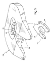
- einen Kupplungssattel einer Sattelkupplung mit einem dazugehörigen demontierten Verschlußhaken in perspektivischer Explosionsdarstellung;
- Fig. 6
- eine Draufsicht auf einen Verschleißring des Kupplungssattels;
- Fig. 7
- einen Schnitt entlang der Linie III-III aus Fig. 6;
- Fig. 8
- eine Draufsicht auf den Verschlußhaken; und
- Fig. 9
- einen Schnitt entlang der Linie V-V aus Fig. 8.
- Fig. 1
- a perspective view, from below, of a kingpin arrangement;
- Fig. 2
- a side view of the kingpin of Figure 1, on an enlarged scale and in half section.
- Fig. 3
- a view similar to Figure 2, but for a modified embodiment.
- Fig. 4
- a further view, similar to Figure 3, but for a further modified embodiment;
- Fig. 5
- a coupling saddle of a fifth wheel with an associated dismantled locking hook in a perspective exploded view;
- Fig. 6
- a plan view of a wear ring of the clutch caliper;
- Fig. 7
- a section along the line III-III of Fig. 6;
- Fig. 8
- a plan view of the locking hook; and
- Fig. 9
- 7 shows a section along the line VV from FIG. 8.
In Fig. 1 bezeichnet 10 als Ganzes eine Königszapfen-Anordnung.
Die Anordnung 10 wird mit ihrer in Fig. 1 nicht
sichtbaren Oberseite an der Unterseite eines Auflieger-Anhängers
befestigt, und zwar bspw. mit Schrauben 12, die durch
einen Ringflansch 13 der Anordnung 10 hindurchreichen.In Fig. 1, 10 designates as a whole a kingpin arrangement.
The
Von der Unterseite des Flansches 13 erstreckt sich nach unten
ein Königszapfen 20. Der Königszapfen 20 hat einen oberen
Abschnitt 21, einen mittleren Abschnitt 22 sowie einen unteren
Abschnitt 23. Der obere und der untere Abschnitt 21, 23
haben denselben Außendurchmesser, während der mittlere
Abschnitt 22 einen geringeren Durchmesser aufweist. Die
Abschnitte 21, 22, 23 sind über konische Übergänge 24, 25
miteinander verbunden (vgl. auch Fig. 2).From the bottom of the
Die Abmessungen des Königszapfens 20 sind genormt. In der
Bundesrepublik Deutschland ist die Norm DIN 74-080 einschlägig.The dimensions of the
Der Königszapfen 20 ist an seiner Oberfläche mit einer Hülse
30 versehen, die die gesamte Umfangsfläche des Königszapfens
20 überdeckt.The
Die Hülse 30 ist in Axialrichtung zweigeteilt und besteht aus
einer ersten Halbschale 31 sowie einer zweiten Halbschale 32,
die jeweils etwa 180 des Umfanges des Königszapfens 20 überdecken.
Sie sind über eine Naht 33 voneinander getrennt.The
Am freien Ende des Königszapfens 20 wird die zweischalige
Hülse 30 mittels eines Deckels 34 gehalten, der auf den unteren
Abschnitt 23 mittels einer axialen Schraube 35 aufgeschraubt
ist. At the free end of the
Aus Fig. 2 ergeben sich weitere Einzelheiten der Anordnung.2 shows further details of the arrangement.
Man erkennt im Halbschnitt auf der linken Seite von Fig. 2,
daß die linke Halbschale 31 der Hülse 30 einstückig ist. Wie
der vergrößerte Ausschnitt 39 zeigt, ist eine Wand 40 der
Hülse 30 mit einer äußeren Schicht 41 sowie einer inneren
Schicht 42 versehen. Die Schichten 41 bzw. 42 bilden damit
eine äußere Oberfläche 45 bzw. eine innere Oberfläche 46 der
Hülse 30.One can see in the half section on the left side of FIG. 2,
that the left half-
Die äußere Oberfläche 45 ist damit die äußere Oberfläche des
Königszapfens 20, während die innere Oberfläche 46 auf einer
Gegenfläche 47 des Königszapfen-Körpers aufliegt.
Die Hülse 30 stellt damit eine schwimmende Lagerung dar, weil
sie einerseits entlang der Gleitpaarung der Oberflächen 46/47
auf dem Königszapfen 20 selbstdrehbar ist, andererseits mit
ihrer äußeren Oberfläche 45 eine Eingriffsfläche für die
Schloßelemente der Sattelkupplung darstellt.The
The
Die Hülse 30 ist auf dem Königszapfen 20 axial elastisch verspannt.The
Im Übergang des Königszapfens 20 zum Flansch 13 ist zu diesem
Zweck ein Ring 60 vorgesehen. Der Ring 60 ist geringfügig in
axialer Richtung auf dem Königszapfen 20 verschiebbar, wie
mit einer Lagerung 61 angedeutet. Zwischen dem Ring 60 und
einer radialen Fläche 63 des Flansches 13 liegt ein O-Ring
62, der in Axialrichtung elastisch wirkt.In the transition of the
Die Hülse 30 ist an ihrem in Fig. 2 oberen Ende mit einer
Schräge 65 versehen, mit der sich die Hülse 30 zu ihrem
freien Ende hin verjüngt. Der Kegelwinkel der Schräge 65 kann
z.B. 45 betragen. The
Der Ring 60 ist demgegenüber mit einer komplementären Gegenschräge
66 versehen, an die sich die Schräge 65 formschlüssig
anlegt.In contrast, the ring 60 has a
In entsprechender Weise ist am unteren freien Ende der Hülse
30 eine Schräge 71 vorgesehen, die formschlüssig an einem
komplementär geformten Kragen 70 am Außenumfang des Deckels
34 anliegt.In a corresponding way is at the lower free end of the sleeve
30 a
Wenn nun der Deckel 34 mittels der axialen Schrauben 35 aufgeschraubt
wird, wird die Hülse 30 mit ihren Schrägen 65, 71
axial verspannt und formschlüssig gehalten.
Die Anordnung ist dabei so getroffen, daß die Hülse 30 auf
dem Königszapfen 10 leicht montiert und demontiert werden
kann. Hierzu sind Schrägen 75, 76 im Bereich der Übergänge
24, 25 z.B. mit dem maximal zulässigen Kegelwinkel von 6
ausgeführt. Dann kann z.B. nach Demontage des Deckels 34 die
linke Halbschale 31 nach außen weggekippt werden, wie mit
einem Pfeil 78 in Fig. 2 angedeutet.If the
The arrangement is such that the
Wenn die in Fig. 2 dargestellte Anordnung für eine neu hergestellte
Kupplungsvorrichtung eingesetzt wird, muß der Königszapfen
20 gegenüber den genormten Werten mit seinen Durchmessern
so dimensioniert werden, daß nach dem Aufsetzen der
Hülse 30 die äußere Formgebung den Normmaßen entspricht.If the arrangement shown in Fig. 2 for a newly manufactured
Coupling device is used, the
Wenn demgegenüber der Umbau einer bereits gebrauchten Kupplungsvorrichtung
geplant ist, muß der Königszapfen an seinem
Umfang so weit abgedreht werden, wie dies der Wandstärke der
Hülse 30 entspricht.If, on the other hand, the conversion of an already used coupling device
is planned, the kingpin on his
Be turned as far as the wall thickness of the
Die Schichten 41, 42 auf beiden Seiten der Wand 40 der Hülse
30 werden vorzugsweise durch thermisches Beschichten aufgebracht.
Besonders bevorzugt ist das Aufbringen einer
kohlenstoffbasierten Schicht, insbesondere einer Schicht, die
im wesentlichen aus amorphem Kohlenstoff besteht. Derartige
Schichten werden in einem sogenannten Schichtabscheidungsverfahren,
insbesondere einem PECVD-Verfahren, aufgebracht.
Die Dicke der Schichten 41, 42 liegt z.B. zwischen 1 und 20
µm. Es entstehen dann diamantähnliche Kohlenstoffschichten
extrem hoher Härten von 3.000 HV, wobei diese Schichten neben
dieser hohen Härte noch eine Elastizität besitzen. Dies führt
in Kombination mit ihrer Härte zu einer sehr hohen Verschleißfestigkeit,
sowohl beim Einkuppeln als auch beim normalen
Fahrbetrieb.The
Es versteht sich, daß zur Verbesserung der Haftung der
Schichten 41, 42 noch entsprechende Haftschichten vorgesehen
werden können, die im allgemeinen aus gesputterten metallischen
Schichten bestehen, bspw. aus Aluminium, Titan oder
Chrom oder Legierungen davon.It is understood that to improve the liability of the
Corresponding adhesive layers are also provided in
Um besonders gute Gleitpaarungen zu erzielen und um die Haftung
der Schichten 41, 42 auf der Wand 40 der Hülse 30 zu
verbessern, wird die Oberfläche der Hülse 30 vorzugsweise vor
dem Aufbringen der Schichten prägepoliert. Beim Prägepolieren
wird die Hülse 30 in eine Drehvorrichtung eingespannt und in
radialer Richtung mit einer polierten Diamantkugel beaufschlagt,
die mit sehr geringem axialen Vorschub bei rotierender
Hülse an deren Oberfläche entlang verfahren wird. Dabei
entsteht ein Verdrängungsprozeß von Werkstoff an der Oberfläche
der Hülse 30, und es entsteht letztendlich eine nahezu
spiegelnde Oberfläche.To achieve particularly good sliding pairings and for the adhesion
of the
In Fig. 3 ist eine Variante zum Ausführungsbeispiel gemäß Fig. 2 dargestellt. 3 is a variant of the embodiment according to Fig. 2 shown.
Ein Königszapfen 80 weist wiederum einen oberen Abschnitt 81,
einen mittleren Abschnitt 82 sowie einen unteren Abschnitt 83
auf. Die äußere Formgebung des Königszapfens 80 entspricht
damit im wesentlichen derjenigen des Königszapfens 20 gemäß
Fig. 1 und 2.A
Im Gegensatz zu dem vorgenannten Ausführungsbeispiel weist
der Körper des Königszapfens 80 jedoch ein separates Unterteil
85 auf, das über eine kegelstumpfförmige Passung 86/87
mit einem Oberteil 88 des Königszapfens 80 verbunden ist.In contrast to the aforementioned embodiment
however, the body of the
Zum Verbinden des Unterteils 85 mit dem Oberteil 88 ist eine
Gewindebohrung 90 im Oberteil 88 vorgesehen. Ein Gewindebolzen
91 mit einem Kopf 92 ist durch eine mit der Gewindebohrung
90 fluchtende Durchgangsbohrung 93 im Kopf 92 hindurchgesteckt
und in die Gewindebohrung 90 eingedreht. Auf
diese Weise ist das Unterteil 85 mit dem Oberteil 88 axial
verschraubt. Die formschlüssige Verbindung im Bereich der
Passung 86/87 ergibt eine höhere Festigkeit gegenüber radialen
Beanspruchungen am freien Ende des Königszapfens 80.To connect the
Am Fuße der Passung 86 des Unterteils 85 ist eine erste
radiale Umfangsschulter 95 vorgesehen. Eine zweite radiale
Umfangsschulter 96 befindet sich an dem in Fig. 3 oberen Ende
des mittleren Abschnitts 82 am Oberteil 88. Schließlich ist
eine dritte radiale Umfangsschulter 97 an dem in Fig. 3 oberen
Ende des oberen Abschnitts 81, wiederum am Oberteil 88,
vorgesehen.At the foot of the fit 86 of the
Der Königszapfen 80 ist mit einer ersten Hülse 100 sowie
einer zweiten Hülse 101 und einem dazwischen liegenden, im
wesentlichen in einer Radialebene liegenden Ring 102 versehen. The
Die erste Hülse 100 stützt sich unten auf der ersten radialen
Umfangsschulter 95 und oben am Ring 102 ab. Der Ring 102
liegt wiederum auf der zweiten radialen Umfangsschulter 96
auf.The
Die zweite Hülse 101 liegt unten auf der Oberseite des insoweit
über das Oberteil 88 vorstehenden Ringes 102 auf und
liegt ferner oben an der dritten radialen Umfangsschulter 97
an.The
Die Anordnung ist in Fig. 3 so getroffen, daß durch das Verschrauben
von Unterteil 85 und Oberteil 88 die Hülsen 100,
101 und der Ring 102 nicht miteinander in axialer Richtung
verspannt werden. Vielmehr ist die Anordnung mit etwas Spiel
so getroffen, daß sich die Hülsen 100, 101 auf den entsprechenden
Umfangsabschnitten des Oberteils 88 im Bereich des
oberen Abschnitts 81 bzw. des mittleren Abschnitts 82 frei
drehen können.The arrangement is made in Fig. 3 so that by screwing
of
Die Hülsen 100, 101 bilden mit ihren Oberflächen 105, 106 die
zu den Oberflächen 26, 27 beim Ausführungsbeispiel gemäß
Fig. 1 und 2 korrespondierenden Laufflächen.With their
Oben links in Fig. 3 ist in weiter vergrößertem Maßstab ausschnittsweise
noch eingezeichnet, daß eine äußere Schicht 103
sowie eine innere Schicht 104 auf beiden Seiten der zweiten
Hülse 101 (und in entsprechender Weise natürlich auch auf der
ersten Hülse 100) vorgesehen sind. Die äußere Oberfläche der
äußeren Schicht 103 ist dabei mit 107 und die innere Oberfläche
der inneren Schicht 104 mit 108 bezeichnet.3 is a section on a further enlarged scale
also shown that an outer layer 103rd
and an
Zur Herstellung des Königszapfens 80 gemäß Fig. 3 (und sinn-gemäß
auch gemäß Fig. 2 und 4) geht man folgendermaßen vor:
Beim Aufarbeiten eines bereits vorhandenen Königszapfens herkömmlicher
Bauart wird dieser an seinem Umfang so abgedreht,
daß er einen Durchmesser erhält, der dem Normdurchmesser
abzüglich der doppelten Wandstärke der Hülsen 100, 101 entspricht.
Ein Aufarbeiten eines teilweise verschlissenen
Königszapfens ist naturgemäß nur dann möglich, wenn der
bereits vorhandene Verschleiß geringer ist als die Wandstärke
der später aufzusetzenden Hülse. Da der nach einschlägigen Empfehlungen zulässige
Gesamtverschleiß bei 2 mm liegt, kann z.B. ein Königszapfen
dann nicht mehr aufgearbeitet werden, wenn der Verschleiß
bereits z.B. 1,8 mm beträgt, die Wandstärke der vorgesehenen
Hülse aber nur 1 mm ist.More conventional when refurbishing an existing kingpin
Type, its circumference is turned so
that it gets a diameter that is the standard diameter
minus the double wall thickness of the
Am freien Ende wird der Königszapfen dann verkürzt und mit
einer z.B. kegelstumpfförmigen Eindrehung entsprechend der
Passung 87 versehen. Schließlich wird der Königszapfen 80
noch mit der zentralen Gewindebohrung 90 versehen.At the free end, the kingpin is then shortened and with
one e.g. truncated cone-shaped recess corresponding to the
Auf den so bearbeiteten Königszapfen werden nun die Elemente
102, 101, 100 aufgeschoben und durch Aufschrauben eines separat
beigestellten Unterteils 85 axial gesichert, wie bereits
beschrieben.The elements are now on the
Fig. 4 zeigt noch eine weitere Variante mit einigen Abweichungen gegenüber dem in Fig. 3 dargestellten Ausführungsbeispiel. Fig. 4 shows yet another variant with some deviations compared to the embodiment shown in Fig. 3.
Bei dem Königszapfen 80a in Fig. 4 wird der Gewindebolzen 91a
von einer Oberseite 109 des Königszapfens 80a eingesteckt.In the king pin 80a in FIG. 4, the threaded
Zu diesem Zweck wird ein Kopf 111 eines leicht konischen Gewindebolzens
91a in eine entsprechende Einsenkung 113 in der
Oberseite 109 eingesetzt. Das Oberteil 88a des Königszapfens
80a ist mit einer entsprechend leicht konischen Durchgangsbohrung
115 versehen, wie mit einem Winkel α von z.B. 1
angedeutet. Ein Gewindeabschnitt 121 am freien Ende des
Gewindebolzens 91a greift demgegenüber in eine Gewindebohrung
117 im Unterteil 85a des Königszapfens 80a ein.For this purpose, a
Der Gewindebolzen 91a wird hierzu nach dem Einstecken in die
konische Durchgangsbohrung 115 axial verpreßt und das Unterteil
85a dann aufgeschraubt.For this purpose, the threaded
Auf diese Weise wird das Material des Unterteils 85a nur in
einem geringstmöglichen Umfange geschwächt, und man erhält
eine ebene Unterseite 125 des Unterteils 85a.In this way, the material of the
Die Anordnung der Hülsen und des Ringes ist gegenüber derjenigen von Fig. 3 unverändert, so daß insoweit auf die Beschreibung zu Fig. 3 verwiesen werden kann.The arrangement of the sleeves and the ring is opposite to that of Fig. 3 unchanged, so that to that extent Description to Fig. 3 can be referenced.
Eine Besonderheit kann noch durch Maßnahmen erreicht werden, wie sie in Fig. 4 oben links in weiter vergrößertem Ausschnitt dargestellt sind:A special feature can still be achieved through measures as in Fig. 4 top left in a further enlarged section are shown:
Man erkennt, daß die äußere Oberfläche 119 der Hülse 101a mit
einer Aufrauhung 123 versehen ist, während die innere Oberfläche
glatt ausgeführt ist.It can be seen that the
Die Rauhtiefe der Aufrauhung 123 ist dabei vorzugsweise so bemessen, daß die Aufrauhung auch auf der äußeren Oberfläche der thermischen Beschichtung wirksam ist. Hierzu wird die Rauhtiefe bspw. größer bemessen als die Dicke der thermischen Beschichtung.The roughness of the roughening 123 is preferably so dimensioned that the roughening also on the outer surface the thermal coating is effective. For this, the Roughness depth, for example, dimensioned larger than the thickness of the thermal Coating.
Der Sinn dieser Maßnahme ist, die Hülse auf ihrer Außenseite mit einem höheren Reibungskoeffizienten zu versehen als auf ihrer Innenseite. Hierdurch wird erreicht, daß die Hülse sich vorzugsweise auf der inneren Oberfläche relativ zum Körper des Königszapfens dreht, während sie auf ihrer Außenfläche, ohne sich zu drehen, am Verschleißring bzw. am Kupplungshaken anliegt.The point of this measure is to put the sleeve on its outside with a higher coefficient of friction than on their inside. This ensures that the sleeve itself preferably on the inner surface relative to the body the kingpin while turning on its outer surface, without turning, on the wear ring or on the coupling hook is applied.
Bei den Ausführungsbeispielen gemäß Fig. 3 und 4 besteht das
Unterteil 85, 85a, insbesondere dessen konischer Dorn im
Bereich der Passung 86/87 aus einem sehr hochwertigen Material.
Er wird vorzugsweise beim Montieren des Königszapfens
80a mittels einer Presse bis zum oberen Anschlag verpreßt und
so angepreßt, daß das umgebende Material des Oberteils 88,
88a im Bereich der Passung 86/87 gespannt wird.In the exemplary embodiments according to FIGS. 3 and 4, this exists
Beim Ausführungsbeispiel gemäß Fig. 4 hat der Gewindebolzen
91a an seinem unteren Ende ein preßgerolltes Gewinde im
Bereich des Gewindeabschnitts 116.4, the threaded
Die Hülse 30 bzw. 100, 101 selbst wird vorzugsweise aus einem
Hartmetall hergestellt.The
In Fig. 5 ist ein mit dem allgemeinen Bezugszeichen 110
bezeichneter Kupplungssattel dargestellt, der Teil einer Sattelkupplung
zur Verbindung einer hier nicht dargestellen Sattelzugmaschine
mit einem nicht dargestellten Sattelzuganhänger
ist. Der Kupplungssattel 110 ist an der Oberseite
des rückwärtigen Endes der Zugmaschine befestigt. 5 is one with the
Der Kupplungssattel 110 weist einen hufeisenförmigen, von dem
Kupplungssattel 110 demontierbaren Verschleißring 112 sowie
einen Verschlußhaken 114 auf, der in Fig. 5 der Übersichtlichkeit
halber getrennt von dem Kupplungssattel 110 dargestellt
ist. Der Verschlußhaken 114 ist normalerweise verschwenkbar
an dem Kupplungssattel 110 befestigt.The
Der Kupplungssattel 110 öffnet sich in rückwärtiger Richtung
mit einem Maul 116, an dessen Grund der Verschleißring 112
angeordnet ist. Der Verschleißring weist eine zylinderabschnittförmige
Oberfläche 118 als Anlagefläche für einen
hier nicht dargestellten Königszapfen auf, der wiederum
Bestandteil des Sattelzuganhängers ist. Die als Anlagefläche
dienende Oberfläche 118 reicht etwa bis zu Flächenendabschnitten
120 und 122, so daß die Oberfläche 118 des Verschleißringes
112 den Königszapfen halbkreisförmig
umschließt. Entsprechend weist der Verschlußhaken 114 eine
als Anlagefläche für den übrigen Umfang des Königszapfens
ausgebildete Oberfläche 120 auf, die bis zu entsprechenden
Flächenendabschnitten 124 und 126 reicht.The
Zum Verbinden des Anhängers mit der Zugmaschine wird der
Königszapfen in das Maul 116 des Kupplungssattels 110 eingefahren,
bis er an der Oberfläche 118 des Verschleißringes 112
anliegt. Darauf wird der verschwenkbar an entsprechender
Stelle des Kupplungssattels 110 befestigte Verschlußhaken 114
so verschwenkt, daß er zusammen mit dem Verschleißring 112
den Königszapfen umschließt. Die Oberfläche 120 des
Verschlußhakens 114 und die Oberfläche 118 des Verschleißringes
112 bilden komplementär zueinander gemeinsam
eine kreisringförmige Lagerung des Königszapfens, der in
dieser Lagerung formschlüssig und drehbar aufgenommen ist.To connect the trailer to the tractor, the
The king pin is inserted into the
In Fig. 6 bis Fig. 9 sind der Verschleißring 112 sowie der
Verschlußhaken 114 näher dargestellt. 6 to 9, the
Der Verschleißring 112 besteht aus einem Grundmaterial 130,
üblicherweise einem Werkzeugstahl. Auf dem Grundmaterial 130
ist eine Haftschicht 132 aus einem Metall, bspw. Titan, in
einer Stärke von etwa 1 µm aufgesputtert. Auf der Haftvermittlungsschicht
132 ist eine kohlenstoffbasierte Schicht
134 von einer Dicke von etwa 10 µm in einem Schichtabscheidungsverfahren,
bspw. einem PECVD-Verfahren (Plasma Enhanced
Chemical Vapor Deposition), abgeschieden worden. Unter
kohlenstoffbasierten Schichten werden reine Kohlenstoffschichten
mit diamantähnlicher Struktur, metallhaltige
Kohlenstoffschichten oder amorphe Kohlenstoffschichten, die
entweder rein oder metallhaltig sind, verstanden.The
Die Haftvermittlungsschicht 132 und die kohlenstoffbasierte
Schicht 134 sind auf der gesamten Oberfläche 118 zwischen den
Flächenendabschnitten 120 und 122 vorgesehen.The
Bei der Verwendung metallhaltiger Kohlenstoffschichten kann
die Haftvermittlungsschicht 132 auch weggelassen werden.When using metal-containing carbon layers can
the
Entsprechend ist auf einem Grundmaterial 136 des Verschlußhakens
114 eine Haftschicht 138 sowie eine kohlenstoffbasierte
Schicht 140, ebenfalls von einer Dicke von etwa 10
µm, abgeschieden worden.Correspondingly, the locking hook is on a
Claims (12)
- A coupling device for connecting a towing vehicle to a semi-trailer, in which a kingpin (20; 80) is arranged on the trailer and a tractor coupling on the towing vehicle, said tractor coupling having locking elements for positive and rotatable engaging substantially rotationally symmetrical surfaces (26, 27; 105, 106) of the kingpin (20; 80), the surfaces (26, 27; 105, 106) being formed by an abrasion-resistant thermal coating (41, 42; 103, 104), characterized in that the surfaces (26, 27; 105, 106) are configurated by outer surfaces (45, 107) of a thermally coated sleeve (30; 100, 101) sitting on the kingpin (20; 80), the sleeve (30; 100, 101), with inner surfaces (46; 108), being rotatably arranged on the kingpin (20; 80).
- The coupling device of claim 1, characterized in that the sleeve (101a) is provided with a roughening (120) on its outer surface (119), the roughening (120) having a surface roughness being greater than the thickness of the thermal coating.
- The coupling device of claim 1 or 2, characterized in that the inner surfaces (46; 108) are likewise configurated by an abrasion-resistant thermal coating.
- The coupling device of one or more of claims 1 through 3, characterized in that the thermal coating is a carbon-based layer, in particular a layer made of substantially amorphous carbon.
- The coupling device of one or more of claims 1 through 4, characterized in that the sleeve (30) is of multi-shelled configuration in the circumferential direction.
- The coupling device of one or more of claims 1 through 5, characterized in that the sleeve (100, 101) is of multi-part configuration in the axial direction.
- The coupling device of claim 6, characterized in that the kingpin (80) comprises an axially multi-part body (85, 88), a lower part (85) arranged at the free end of the kingpin being removable, and the several sleeves (100, 101) being slidable, when the lower part has been removed, onto an upper part (88) of the body (85, 88).
- The coupling device of one or more of claims 1 through 7, characterized in that the sleeves (100, 101) have a different diameter and rest, on axially opposite sides, against a disk (102) which is slid onto the body (85, 88) and extends substantially radially.
- The coupling device of claims 7 or 8, characterized in that the sleeves (100, 101) are retained axially by thread-joining of the several parts of the body (85, 88).
- A coupling device, in particular as defined in one or more of claims 1 through 9, comprising a coupling plate (110), attached to the towing vehicle, which has a wear ring (112) coacting with a kingpin of the semi-trailer as well as a locking hook (114), surfaces (118, 124) of the wear ring (112) and of the locking hook (114) which come into contact with the kingpin having an anti-friction layer, characterized in that the anti-friction layer is a carbon-based layer (134, 140).
- A method for converting coupling devices for connecting a towing vehicle to a semi-trailer, in which a kingpin (20; 80) is arranged on the trailer and a tractor coupling on the towing vehicle, said tractor coupling having locking elements for positive and rotatable engaging substantially rotationally symmetrical surfaces of the kingpin (20; 80), into a state in which lubricant-free and thus maintenance-free operation of the coupling device is possible, comprising the steps:a) lathe-turning the surfaces of the kingpin (20; 80) off by a predefined overmeasure;b) manufacturing a sleeve (30; 100, 101) for placement on the turned-off kingpin (20; 80), the wall thickness of the sleeve (30; 100, 101) being substantially identical to the overmeasure;c) thermally coating at least the outer surface of the sleeve (30; 100, 101) with an abrasion-resistant coating (41, 103); andd) placing the sleeve (30; 100, 101) onto the turned-off kingpin (20; 80) in such a way that the sleeve (30; 100, 101) is rotatable on the kingpin (20; 80).
- The method of claim 11, characterized in that the kingpin (80) consists of two parts such that a lower part (85) arranged at the free end of the kingpin (80) is removable; and the sleeve (100, 101), when the lower part (85) has been removed, is slid onto an upper part (88) of the kingpin (80), wherein, preferably, after the sleeve (100, 101) has been slid on, the lower part (85) is axially thread-joined to the upper part (88), and the sleeve (100, 101) is thereby axially retained.
Applications Claiming Priority (7)
| Application Number | Priority Date | Filing Date | Title |
|---|---|---|---|
| DE19624803 | 1996-06-21 | ||
| DE1996124803 DE19624803C2 (en) | 1996-06-21 | 1996-06-21 | Fifth wheel |
| DE19644265 | 1996-10-24 | ||
| DE19644265 | 1996-10-24 | ||
| DE19647211A DE19647211C2 (en) | 1996-10-24 | 1996-11-15 | Coupling device for connecting a towing vehicle to a semi-trailer and method for converting coupling devices |
| DE19647211 | 1996-11-15 | ||
| PCT/EP1997/003205 WO1997049600A1 (en) | 1996-06-21 | 1997-06-19 | Coupling device for connecting a towing vehicle to a semi-trailer, and process for the modification of coupling devices |
Publications (3)
| Publication Number | Publication Date |
|---|---|
| EP0906214A1 EP0906214A1 (en) | 1999-04-07 |
| EP0906214B1 true EP0906214B1 (en) | 2002-02-13 |
| EP0906214B2 EP0906214B2 (en) | 2010-01-20 |
Family
ID=27216369
Family Applications (1)
| Application Number | Title | Priority Date | Filing Date |
|---|---|---|---|
| EP97928248A Expired - Lifetime EP0906214B2 (en) | 1996-06-21 | 1997-06-19 | Coupling device for connecting a towing vehicle to a semi-trailer, and process for the modification of coupling devices |
Country Status (7)
| Country | Link |
|---|---|
| US (1) | US6220617B1 (en) |
| EP (1) | EP0906214B2 (en) |
| JP (1) | JP2000512592A (en) |
| AT (1) | ATE213209T1 (en) |
| AU (1) | AU3261597A (en) |
| ES (1) | ES2172797T5 (en) |
| WO (1) | WO1997049600A1 (en) |
Families Citing this family (11)
| Publication number | Priority date | Publication date | Assignee | Title |
|---|---|---|---|---|
| JP2005516849A (en) * | 2002-02-11 | 2005-06-09 | ザ ホランド グループ,インコーポレイテッド | A fifth wheel hitch that requires only a small amount of lubricant or no need at all |
| US7232767B2 (en) * | 2003-04-01 | 2007-06-19 | Mattson Technology, Inc. | Slotted electrostatic shield modification for improved etch and CVD process uniformity |
| US8814861B2 (en) | 2005-05-12 | 2014-08-26 | Innovatech, Llc | Electrosurgical electrode and method of manufacturing same |
| US7147634B2 (en) | 2005-05-12 | 2006-12-12 | Orion Industries, Ltd. | Electrosurgical electrode and method of manufacturing same |
| US7762167B2 (en) * | 2007-04-20 | 2010-07-27 | Lefebvre Richard M | Methods of modifying a trailer kingpin in situ |
| US7766361B2 (en) * | 2007-10-25 | 2010-08-03 | Saf-Holland, Inc. | Rotating fifth wheel hitch kingpin assembly |
| DE102010024843B4 (en) * | 2010-06-23 | 2012-05-31 | Patrick Kramer | Vehicle with at least one crane |
| US9238390B2 (en) | 2012-07-03 | 2016-01-19 | Rel, Inc. | Composite articles, wear plates and methods |
| US9016708B2 (en) | 2013-05-14 | 2015-04-28 | Saf-Holland, Inc. | Fifth wheel hitch kingpin assembly |
| US8960704B2 (en) | 2013-05-14 | 2015-02-24 | Saf-Holland, Inc. | Fifth wheel hitch kingpin assembly |
| WO2019142137A2 (en) | 2018-01-19 | 2019-07-25 | Saf-Holland, Inc. | Kingpin assembly with rotation sensor arrangement |
Family Cites Families (18)
| Publication number | Priority date | Publication date | Assignee | Title |
|---|---|---|---|---|
| US2973210A (en) * | 1959-05-15 | 1961-02-28 | Bill Anderson Spring Service I | Kingpin assembly |
| US3870342A (en) * | 1973-01-11 | 1975-03-11 | Binkley Co | Retractable king pin and clamping assembly |
| US3894676A (en) * | 1973-10-15 | 1975-07-15 | Chemetron Corp | Method for construction of railway bolster |
| GB1582231A (en) | 1976-08-13 | 1981-01-07 | Nat Res Dev | Application of a layer of carbonaceous material to a surface |
| US4236863A (en) * | 1978-12-22 | 1980-12-02 | Dresser Industries, Inc. | Center pin assembly for power shovels |
| US4428595A (en) * | 1982-03-01 | 1984-01-31 | Holland Hitch Company | Fifth wheel hitch |
| US4478425A (en) * | 1982-10-21 | 1984-10-23 | Benko John M | Fifth wheel plate |
| US4592566A (en) * | 1984-07-09 | 1986-06-03 | Kyokuto Kaihatsu Kogyo Co, Ltd. | Coupling mechanism for king pin |
| DE3530467A1 (en) † | 1985-08-27 | 1987-03-05 | Walter Hunger | Fifth-wheel coupling |
| JPS62127466A (en) * | 1985-11-28 | 1987-06-09 | Toshiba Corp | Member deposited with ceramics |
| CH674494A5 (en) * | 1987-10-08 | 1990-06-15 | Fischer Ag Georg | |
| US4828328A (en) * | 1988-05-03 | 1989-05-09 | Bowman Dan H | Replacement wheel bearing spindle |
| US4986923A (en) | 1989-06-27 | 1991-01-22 | Amoco Corporation | Front-wheel drive grease with synergistic sulfate and carbonate additive system |
| US5223161A (en) | 1989-06-27 | 1993-06-29 | Amoco Corporation | Extreme pressure and wear resistant grease with synergistic sulfate and carboxylate additive system |
| CH684575A5 (en) * | 1990-11-30 | 1994-10-31 | Roland Hauert Dr Manfred Roth | Method of reducing the coefficients of friction and of increasing the resistance to wear of a body which slides on solid water |
| US5411281A (en) * | 1993-11-23 | 1995-05-02 | Poirier; Bertin | Fifth wheel construction having rotatable bearing plate |
| US5746438A (en) * | 1995-03-03 | 1998-05-05 | Jost--Werke AG | Fifth wheel |
| DE19637511A1 (en) * | 1996-09-13 | 1998-03-19 | Hunger Walter Dr Ing E H | Lorry trailer coupling bearing which prolongs life and reduces environmental contamination |
-
1997
- 1997-06-19 JP JP10502291A patent/JP2000512592A/en active Pending
- 1997-06-19 AT AT97928248T patent/ATE213209T1/en not_active IP Right Cessation
- 1997-06-19 ES ES97928248T patent/ES2172797T5/en not_active Expired - Lifetime
- 1997-06-19 EP EP97928248A patent/EP0906214B2/en not_active Expired - Lifetime
- 1997-06-19 WO PCT/EP1997/003205 patent/WO1997049600A1/en active IP Right Grant
- 1997-06-19 AU AU32615/97A patent/AU3261597A/en not_active Abandoned
- 1997-06-19 US US09/214,149 patent/US6220617B1/en not_active Expired - Lifetime
Also Published As
| Publication number | Publication date |
|---|---|
| AU3261597A (en) | 1998-01-14 |
| EP0906214B2 (en) | 2010-01-20 |
| JP2000512592A (en) | 2000-09-26 |
| EP0906214A1 (en) | 1999-04-07 |
| ES2172797T5 (en) | 2010-05-26 |
| WO1997049600A1 (en) | 1997-12-31 |
| US6220617B1 (en) | 2001-04-24 |
| ATE213209T1 (en) | 2002-02-15 |
| ES2172797T3 (en) | 2002-10-01 |
Similar Documents
| Publication | Publication Date | Title |
|---|---|---|
| EP0906214B1 (en) | Coupling device for connecting a towing vehicle to a semi-trailer, and process for the modification of coupling devices | |
| DE1915932A1 (en) | Bearing device for a drive wheel of a motor vehicle | |
| DE3143607C2 (en) | ||
| DE60112336T2 (en) | WHEEL HOLDER FOR VEHICLES WITH DISC BRAKES | |
| DE19742027A1 (en) | Unit for motor vehicle wheels | |
| DE3544222A1 (en) | DIFFERENTIAL AXLE FOR RAILWAY CARS | |
| DE1908546A1 (en) | Steering drive axle assembly | |
| EP1155829A2 (en) | Exchangeable cylinder element in an electrographic printing unit | |
| DE19740597B4 (en) | disc brake | |
| DE2003028A1 (en) | Disc brake | |
| DE19647211C2 (en) | Coupling device for connecting a towing vehicle to a semi-trailer and method for converting coupling devices | |
| DE20319147U1 (en) | Wheel support unit for a motor vehicle has a wheel support and an axle arm fitted onto the support for accommodating a wheel | |
| DE102020202217A1 (en) | Spherical ball joint | |
| EP1069334A1 (en) | Retainer element for disc brake pads | |
| DE4304857C2 (en) | Fifth wheel | |
| EP0058732A1 (en) | Low-friction saddle coupling | |
| DE4225903C2 (en) | Wheel adapter for truck wheels | |
| DE102004034565A1 (en) | Axle leg or wheel trunk with integrated brake plate for partial disk brake in motor vehicle has inlet contours, primarily supporting braking forces and connected with each other, for brake pads which are arranged on both sides of brake disk | |
| EP3976987A1 (en) | Steering knuckle of a utility vehicle | |
| DE10057587A1 (en) | Wheel bearing for trailer axle with separate running layer in hub with outside against internal surface of hub and inside forming outer running surface of bearing | |
| DE19624803C2 (en) | Fifth wheel | |
| DE19637511A1 (en) | Lorry trailer coupling bearing which prolongs life and reduces environmental contamination | |
| EP0507342B1 (en) | Fifth wheel traction coupling with a supply of grease for the locking zone | |
| WO1999019156A1 (en) | Wheel bearing | |
| DE19836678C1 (en) | Wheel bearing for the driven wheel of a motor vehicle |
Legal Events
| Date | Code | Title | Description |
|---|---|---|---|
| PUAI | Public reference made under article 153(3) epc to a published international application that has entered the european phase |
Free format text: ORIGINAL CODE: 0009012 |
|
| 17P | Request for examination filed |
Effective date: 19990114 |
|
| AK | Designated contracting states |
Kind code of ref document: A1 Designated state(s): AT CH DE ES FR GB IT LI NL SE |
|
| 17Q | First examination report despatched |
Effective date: 19990702 |
|
| GRAG | Despatch of communication of intention to grant |
Free format text: ORIGINAL CODE: EPIDOS AGRA |
|
| GRAG | Despatch of communication of intention to grant |
Free format text: ORIGINAL CODE: EPIDOS AGRA |
|
| GRAG | Despatch of communication of intention to grant |
Free format text: ORIGINAL CODE: EPIDOS AGRA |
|
| GRAH | Despatch of communication of intention to grant a patent |
Free format text: ORIGINAL CODE: EPIDOS IGRA |
|
| GRAH | Despatch of communication of intention to grant a patent |
Free format text: ORIGINAL CODE: EPIDOS IGRA |
|
| GRAA | (expected) grant |
Free format text: ORIGINAL CODE: 0009210 |
|
| REG | Reference to a national code |
Ref country code: GB Ref legal event code: IF02 |
|
| AK | Designated contracting states |
Kind code of ref document: B1 Designated state(s): AT CH DE ES FR GB IT LI NL SE |
|
| PG25 | Lapsed in a contracting state [announced via postgrant information from national office to epo] |
Ref country code: NL Free format text: LAPSE BECAUSE OF FAILURE TO SUBMIT A TRANSLATION OF THE DESCRIPTION OR TO PAY THE FEE WITHIN THE PRESCRIBED TIME-LIMIT Effective date: 20020213 |
|
| REF | Corresponds to: |
Ref document number: 213209 Country of ref document: AT Date of ref document: 20020215 Kind code of ref document: T |
|
| REG | Reference to a national code |
Ref country code: CH Ref legal event code: EP |
|
| REF | Corresponds to: |
Ref document number: 59706391 Country of ref document: DE Date of ref document: 20020321 |
|
| PG25 | Lapsed in a contracting state [announced via postgrant information from national office to epo] |
Ref country code: SE Free format text: LAPSE BECAUSE OF FAILURE TO SUBMIT A TRANSLATION OF THE DESCRIPTION OR TO PAY THE FEE WITHIN THE PRESCRIBED TIME-LIMIT Effective date: 20020513 |
|
| GBT | Gb: translation of ep patent filed (gb section 77(6)(a)/1977) |
Effective date: 20020517 |
|
| PG25 | Lapsed in a contracting state [announced via postgrant information from national office to epo] |
Ref country code: AT Free format text: LAPSE BECAUSE OF NON-PAYMENT OF DUE FEES Effective date: 20020619 |
|
| PG25 | Lapsed in a contracting state [announced via postgrant information from national office to epo] |
Ref country code: LI Free format text: LAPSE BECAUSE OF NON-PAYMENT OF DUE FEES Effective date: 20020630 Ref country code: CH Free format text: LAPSE BECAUSE OF NON-PAYMENT OF DUE FEES Effective date: 20020630 |
|
| NLV1 | Nl: lapsed or annulled due to failure to fulfill the requirements of art. 29p and 29m of the patents act | ||
| ET | Fr: translation filed | ||
| REG | Reference to a national code |
Ref country code: ES Ref legal event code: FG2A Ref document number: 2172797 Country of ref document: ES Kind code of ref document: T3 |
|
| PLBQ | Unpublished change to opponent data |
Free format text: ORIGINAL CODE: EPIDOS OPPO |
|
| PLBI | Opposition filed |
Free format text: ORIGINAL CODE: 0009260 |
|
| 26 | Opposition filed |
Opponent name: JOST-WERKE GMBH & CO. KG Effective date: 20021113 |
|
| PLAV | Examination of admissibility of opposition |
Free format text: ORIGINAL CODE: EPIDOS OPEX |
|
| PLBF | Reply of patent proprietor to notice(s) of opposition |
Free format text: ORIGINAL CODE: EPIDOS OBSO |
|
| REG | Reference to a national code |
Ref country code: CH Ref legal event code: PL |
|
| PLBF | Reply of patent proprietor to notice(s) of opposition |
Free format text: ORIGINAL CODE: EPIDOS OBSO |
|
| PLBB | Reply of patent proprietor to notice(s) of opposition received |
Free format text: ORIGINAL CODE: EPIDOSNOBS3 |
|
| PLBQ | Unpublished change to opponent data |
Free format text: ORIGINAL CODE: EPIDOS OPPO |
|
| PLAB | Opposition data, opponent's data or that of the opponent's representative modified |
Free format text: ORIGINAL CODE: 0009299OPPO |
|
| R26 | Opposition filed (corrected) |
Opponent name: JOST-WERKE GMBH & CO. KG Effective date: 20021113 |
|
| PLAB | Opposition data, opponent's data or that of the opponent's representative modified |
Free format text: ORIGINAL CODE: 0009299OPPO |
|
| PUAH | Patent maintained in amended form |
Free format text: ORIGINAL CODE: 0009272 |
|
| STAA | Information on the status of an ep patent application or granted ep patent |
Free format text: STATUS: PATENT MAINTAINED AS AMENDED |
|
| 27A | Patent maintained in amended form |
Effective date: 20100120 |
|
| AK | Designated contracting states |
Kind code of ref document: B2 Designated state(s): AT CH DE ES FR GB IT LI NL SE |
|
| REG | Reference to a national code |
Ref country code: ES Ref legal event code: DC2A Date of ref document: 20100326 Kind code of ref document: T5 |
|
| REG | Reference to a national code |
Ref country code: FR Ref legal event code: PLFP Year of fee payment: 20 |
|
| PGFP | Annual fee paid to national office [announced via postgrant information from national office to epo] |
Ref country code: GB Payment date: 20160621 Year of fee payment: 20 Ref country code: ES Payment date: 20160614 Year of fee payment: 20 |
|
| PGFP | Annual fee paid to national office [announced via postgrant information from national office to epo] |
Ref country code: FR Payment date: 20160627 Year of fee payment: 20 |
|
| PGFP | Annual fee paid to national office [announced via postgrant information from national office to epo] |
Ref country code: IT Payment date: 20160628 Year of fee payment: 20 Ref country code: DE Payment date: 20160723 Year of fee payment: 20 |
|
| REG | Reference to a national code |
Ref country code: DE Ref legal event code: R071 Ref document number: 59706391 Country of ref document: DE |
|
| REG | Reference to a national code |
Ref country code: GB Ref legal event code: PE20 Expiry date: 20170618 |
|
| PG25 | Lapsed in a contracting state [announced via postgrant information from national office to epo] |
Ref country code: GB Free format text: LAPSE BECAUSE OF EXPIRATION OF PROTECTION Effective date: 20170618 |
|
| REG | Reference to a national code |
Ref country code: ES Ref legal event code: FD2A Effective date: 20180508 |
|
| PG25 | Lapsed in a contracting state [announced via postgrant information from national office to epo] |
Ref country code: ES Free format text: LAPSE BECAUSE OF EXPIRATION OF PROTECTION Effective date: 20170620 |