EP0905827B1 - Verbesserter Chipkarteverbinder - Google Patents
Verbesserter Chipkarteverbinder Download PDFInfo
- Publication number
- EP0905827B1 EP0905827B1 EP98307830A EP98307830A EP0905827B1 EP 0905827 B1 EP0905827 B1 EP 0905827B1 EP 98307830 A EP98307830 A EP 98307830A EP 98307830 A EP98307830 A EP 98307830A EP 0905827 B1 EP0905827 B1 EP 0905827B1
- Authority
- EP
- European Patent Office
- Prior art keywords
- cover
- card
- base
- connector
- electrical
- Prior art date
- Legal status (The legal status is an assumption and is not a legal conclusion. Google has not performed a legal analysis and makes no representation as to the accuracy of the status listed.)
- Expired - Lifetime
Links
Images


Classifications
-
- G—PHYSICS
- G06—COMPUTING; CALCULATING OR COUNTING
- G06K—GRAPHICAL DATA READING; PRESENTATION OF DATA; RECORD CARRIERS; HANDLING RECORD CARRIERS
- G06K13/00—Conveying record carriers from one station to another, e.g. from stack to punching mechanism
- G06K13/02—Conveying record carriers from one station to another, e.g. from stack to punching mechanism the record carrier having longitudinal dimension comparable with transverse dimension, e.g. punched card
- G06K13/08—Feeding or discharging cards
- G06K13/085—Feeding or discharging cards using an arrangement for locking the inserted card
- G06K13/0862—Feeding or discharging cards using an arrangement for locking the inserted card the locking arrangement being of the rotate-slide and lock type, such as, e.g. common in mobile phones
-
- H—ELECTRICITY
- H01—ELECTRIC ELEMENTS
- H01R—ELECTRICALLY-CONDUCTIVE CONNECTIONS; STRUCTURAL ASSOCIATIONS OF A PLURALITY OF MUTUALLY-INSULATED ELECTRICAL CONNECTING ELEMENTS; COUPLING DEVICES; CURRENT COLLECTORS
- H01R12/00—Structural associations of a plurality of mutually-insulated electrical connecting elements, specially adapted for printed circuits, e.g. printed circuit boards [PCB], flat or ribbon cables, or like generally planar structures, e.g. terminal strips, terminal blocks; Coupling devices specially adapted for printed circuits, flat or ribbon cables, or like generally planar structures; Terminals specially adapted for contact with, or insertion into, printed circuits, flat or ribbon cables, or like generally planar structures
- H01R12/70—Coupling devices
- H01R12/82—Coupling devices connected with low or zero insertion force
- H01R12/83—Coupling devices connected with low or zero insertion force connected with pivoting of printed circuits or like after insertion
-
- H—ELECTRICITY
- H01—ELECTRIC ELEMENTS
- H01R—ELECTRICALLY-CONDUCTIVE CONNECTIONS; STRUCTURAL ASSOCIATIONS OF A PLURALITY OF MUTUALLY-INSULATED ELECTRICAL CONNECTING ELEMENTS; COUPLING DEVICES; CURRENT COLLECTORS
- H01R12/00—Structural associations of a plurality of mutually-insulated electrical connecting elements, specially adapted for printed circuits, e.g. printed circuit boards [PCB], flat or ribbon cables, or like generally planar structures, e.g. terminal strips, terminal blocks; Coupling devices specially adapted for printed circuits, flat or ribbon cables, or like generally planar structures; Terminals specially adapted for contact with, or insertion into, printed circuits, flat or ribbon cables, or like generally planar structures
- H01R12/70—Coupling devices
- H01R12/71—Coupling devices for rigid printing circuits or like structures
- H01R12/712—Coupling devices for rigid printing circuits or like structures co-operating with the surface of the printed circuit or with a coupling device exclusively provided on the surface of the printed circuit
- H01R12/716—Coupling device provided on the PCB
-
- H—ELECTRICITY
- H01—ELECTRIC ELEMENTS
- H01R—ELECTRICALLY-CONDUCTIVE CONNECTIONS; STRUCTURAL ASSOCIATIONS OF A PLURALITY OF MUTUALLY-INSULATED ELECTRICAL CONNECTING ELEMENTS; COUPLING DEVICES; CURRENT COLLECTORS
- H01R2201/00—Connectors or connections adapted for particular applications
- H01R2201/16—Connectors or connections adapted for particular applications for telephony
Definitions
- the present invention relates generally to an electrical connector which supports an integrated circuit (IC) card to a printed circuit board. More particularly, the present invention is directed to a chip card connector which provides for the easy insertion and removal of the chip card from the connector.
- IC integrated circuit
- a smart card is a card incorporating at least one electronic component to which electrical connection must be made. These cards include contact pads so as to allow electrical connection to the electronic component on the card. Smart cards are commonly used in various consumer oriented apparatus and machines such as telephones, bank machines and the like.
- mini-card One particular type of smart card commonly used in telephones, especially cellular telephones, is a mini-card or a mini-SIM (subscriber identity module) card. These cards have a particular industry-accepted standard for size, shape and location of the electronic components and contact pads. These mini-SIM cards are typically installed in the apparatus, such as the cellular phone, by a trained installer.
- SIM subscriber identity module
- an electrical connector In order to effect electrical connection between the mini-SIM card and a printed circuit board within the cellular phone, an electrical connector is employed. These connectors also are manufactured in an industry-accepted configuration so that the mini-SIM card may be accommodated by the connector. However, for various purposes, such as for example, to change the subscriber identity, it may be necessary to replace the mini-SIM card within the phone. Thus, the electrical connector used to support the mini-SIM card in the phone must permit the easy replacement of cards therein. The art has seen numerous electrical connectors specifically designed for use in removably connecting various types of smart cards.
- U.S. Patent No. 5,603,629 discloses a connector for a mini-SIM type smart card having a base supporting a plurality of electrical contacts.
- the base is mounted to a printed circuit board in the phone.
- a cover is pivotally attached to the base and includes a slot for retention of the card therein.
- the cover may be pivotally closed onto the base to place the pads on the card in electrical connection with the contacts held in the base.
- the cover is movable from an open position permitting insertion and removal of the card to a closed position establishing such electrical connection.
- U.S. Patent No. 4,820,186 provides another example of a smart card connector having a cover which pivotally mounts to the base.
- the card may be inserted and removed from the cover from an open position.
- the cover is pivotally rotated to a closed position establishing electrical connection with the contacts in the base.
- the cover is spring loaded with respect to the base so as to mechanically lock the cover to the base in the closed position.
- U.S. Patent No. 5,320,552 also describes a smart card connector having a cover for accommodating the smart card and which is pivotally mounted to a base.
- the cover is also movable linearly movable over the smart card to lock the cover to the base.
- U.S. Patent No. 5,718,609 discloses a connector for a SIM type smart card having a base supporting a plurality of electrical contacts, and a cover for supporting the smart card.
- the cover can be pivoted into the plane of the base into a closed position and the moved in a translatory manner to lock the cover into a locked position.
- the electrical contacts are not biased. Instead, a tongue shaped pressure spring is provided on the cover which biases the smart card against the contacts when the cover is moved into its locked position.
- the present invention provides an electrical connector for connecting contact pads of an IC card to a printed circuit board
- a connector housing having a base supportable on said printed circuit board and a cover movably supported to said base, said cover having a depending foot portion downwardly directed therefrom, and said base including a pair of transversely spaced shoulders extending upwardly therefrom, each of said shoulders having a tapered upper surface such that upon closing said cover said IC card can be moved within said cover so as to be linearly spaced a distance from said depending foot portion; a plurality of elongate electrical contacts supported by said base, each said contact including a spring element for deflectable electrical engagement with said contact pads of said IC card and a contact tail extending from said base for termination to said printed circuit board; and card support means included on said cover for insertably supporting said IC card on said cover for movement therewith; said cover being pivotally movable from an open position for permitting insertion and removal of said card from said cover to a closed position with said contact pads of said IC card being positioned adjacent said
- the cover is pivotally movable from an open position permitting insertion and removal of the card from the cover to a closed position. In such closed position the contact pads of the IC card are positioned adjacent but not in full electrical engagement with the spring elements.
- the cover is then linearly movable from the closed position to a locked position, for locking of the cover to the base and for moving the contact pads of the IC card over the spring elements and into wiping electrical engagement therewith.
- the connector includes a card support means on the cover for supporting IC card therein.
- the card support means includes a plurality of retaining members formed integrally with the cover.
- the card support means and the cover define a slot for the insertion and the removal of the card therein.
- the present invention provides an electrical connector 10 which may be used to mechanically and electrically connect a chip card 12 to a printed circuit board (not shown).
- the present invention has particular utility in mechanically and electrically connecting chip cards of the type known as smart cards which provide an electronic component on the card which is electrically accessible by electrically conductive contact pads 14 on one surface of the chip card 12.
- the particular embodiment of the chip card shown herein is a mini-SIM card and connector 10 may be particularly used in consumer accessible electronics, more particularly cellular phones. It is desirable to insert and remove chip cards 12 from connector 10 for various purposes such as to change the subscriber's identity with regard to a particular cellular phone.
- the connector of the present invention is designed to provide ease of insertion and removal of the chip card 12 with respect to connector 10 and also to provide reliable mechanical and electrical interconnection therewith.
- Connector 10 of the present invention includes a two-part connector housing 16 including a base 18 and a cover 20 mounted to base 18.
- Housing 16 may be formed of suitable insulative plastic.
- Base 18 is generally an elongate flat planar member having a plurality of apertures 22 therethrough.
- Base 18 supports a plurality of electrical contacts 24 within apertures 22.
- Contacts 24 are formed of an electrically conductive material and are elongate members having oppositely directed contact tails 26 extending from base 18 for solder connection to the printed circuit board.
- Contacts 24 further include at the end opposite tails 26 spring contact elements 28 extending above the plane of base 18. Spring contact elements 28 are designed for resilient electrical engagement with the contact pads 14 of chip card 12 as will be described in further detail hereinbelow.
- Base 18 includes a polarization tab 30 at one corner thereof for polarized accommodation of chip card 12 preventing chip cards from being positioned in connector 10 in an incorrect orientation.
- Base 18 further includes at one end 18a thereof a pair of transversely spaced shoulders 32 which extend upwardly from base 18. Shoulders 32 provide for movable accommodation of cover 20 on base 18 in a manner which will be described in further detail hereinbelow.
- Base 18 also includes a pair of spaced apart laterally projecting ears 43 along each longitudinal side thereof. Ears 43 define spaces 50 therebetween.
- Cover 20 is generally an elongate member having a planar cover wall 34 and a pair of parallel side walls 36 depending from cover wall 34. Cover 20 is of size and shape so as to accommodate chip card 12 along an undersurface 34a of cover wall 34. Cover 20 further includes a downwardly directed central foot portion 38 at one end 20a which provides a mechanical stop and a seat for an end 12a of chip card 12 as it is inserted into cover 20.
- the side walls 36 of cover 20 each include a pair of longitudinally spaced inwardly directed ledges 40 which are spaced a distance from the undersurface 34a of cover wall 34. The spacing between ledges 40 and undersurface 34a is slightly larger than the thickness of chip card 12 so as to form slot 21 for accommodating chip card 12 therein.
- undersurface 34a of cover 20 also includes a downwardly directed central protrusion 42.
- Protrusion 42 extends in a direction towards ledges 40 so as to decrease the effective width of slot 21 defined therebetween, so as to provide frictional retainment of the chip card 12 when it is inserted therein.
- Such frictional retaining of the chip card 12 helps positionally stabilize the chip card as the cover 20 is closed onto base 18 as will be described in further detail hereinbelow.
- Cover 20 further includes adjacent end 20a a pair of inwardly directed pivot pins 44 which are designed for accommodation within channels 46 of shoulders 32 of base 18.
- the channels 46 include a pair of spaced-apart pin receiving recesses 46a and 46b. These recesses permit the accommodation of cover 20 on base 18 at two longitudinally spaced locations.
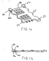
- cover 20 is shown in the open position with respect to base 18.
- the pivot pins 44 of cover 20 (Figs. 10 and 12) are positioned within rear recess 46a of channels 46 (Fig. 1b).
- the cover 20 is pivoted to a position with respect to base 18 approximately shown in Figures 1 and 3.
- the chip card may be inserted into the slot 21 defined between the undersurface 34a of cover wall 34 and the protruding ledges 40 from sidewalls 36.
- the chip card 12 is inserted until the end 12a of the chip card abuts against depending foot portion 38 as shown in Figures 2 and 3.
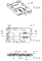
- the cover 20 is then pivoted down towards base 18 about pivot pins 44 so that the ledges 40 reside in respective spaces 50 between ears 43 of base 18.
- the chip card 12 is held in frictional engagement within cover 20 moving only under the ramped urging of tapered upper surface 32a of shoulder 32 by the frictional engagement of the chip card 12 with protrusion 40 extending from the undersurface 34a of top wall 34. Such frictional engagement is sufficient to prevent unwanted movement of the chip card 12 within the slot 21 of cover 20 yet permit the chip card to be ramped forward upon pivotally closing cover 20.
- the cover 20 may be locked to the base to mechanically secure the cover to the base and further to move the contact pads 28 in a wiping action over the spring contact elements 14 and into electrical engagement therewith.
- Such wiping movement provides sufficient frictional engagement, due to the spring bias of the spring contact elements 28, to remove any dust or debris which may exist at the interface of spring contact elements 28 and contact pads 14.
- such forward movement in a direction of arrow A serves to mechanically lock the cover to base 18.
- Downwardly directed ledges 40 are configured to frictionally accommodate ears 43 of base 18 upon such linear movement of cover 20 so as to latch with the ears 43 to thereby mechanically secure the cover 20 to the base 18 preventing the cover from being pivotally opened in the locked position.
- Such locking of cover 20 to base 18 assures the maintenance of electrical engagement between contact pads 14 and spring contact elements 28 as well as positionally retains chip card 12 within connector 10.
- the cover 20 In order to remove chip card 12 from connector 10 for repair or replacement, the cover 20 is moved linearly rearward in a direction opposite arrow A (Fig. 9). The pivot pins 44 move out of forward recess 46b and into rear recess 46a. Once cover 20 is moved to this position, the ledges 40 of cover 20 clear the ears 43 of base 18. This allows the cover to be pivoted upwards to a position shown in Figures 1, 2 and 3. In this position, the installer may manually grasp the opposite edge 12b of card 12, access being provided by an undercut 52 in the leading edge of cover 20. The installer may then repair or replace chip card 12 and reconnect the chip card in connector 10.
- the present invention provides superior electrical connection between the contact pads 14 of chip card 12 and the spring contact elements 28 of contacts 24 in base 18 by providing for wiping engagement therebetween.
- wiping engagement is provided by moving the chip card with the cover 20 in a linear direction from a closed but unlocked position to a locked position.
- assurance is provided that the chip card is properly secured within the connector as unless locking engagement is provided between the cover and the base, the contact pads of the chip card will not be in full operating electrical engagement with the contacts 24 of the base. Such positioning may not provide proper electrical functioning of the device. It is only upon locking of the cover to the base that the pads of chip card will be in full electrical engagement of the contacts of the connector.
Landscapes
- Physics & Mathematics (AREA)
- General Physics & Mathematics (AREA)
- Engineering & Computer Science (AREA)
- Theoretical Computer Science (AREA)
- Coupling Device And Connection With Printed Circuit (AREA)
- Details Of Connecting Devices For Male And Female Coupling (AREA)
Claims (3)
- Ein elektrischer Verbinder (10) zum Anschließen der Kontaktinseln (14) einer Chipkarte (12) an eine Leiterplatte mit:einem Verbindergehäuse (16) mit einer auf der Leiterplatte zu tragenden Basis (18) und einem gegenüber der Basis (18) verschiebbar gehaltenen Deckel (20) mit einem von diesem nach unten gerichteten herabhängenden Fußabschnitt (38), wobei die Basis (18) zwei von diesem in Richtung nach oben ausgehende, in Querrichtung auseinanderliegende Schultern (32) aufweist und jede der Schultern (32) eine abgeschrägte Oberseite (32a) aufweist derart, daß bei Schließen des Deckels die Chipkarte (12) in diesem verschoben werden kann zum Ausbilden eines Abstands in linearer Richtung zum herabhängenden Fußabschnitt (38),mehreren von der Basis (18) getragenen langen elektrischen Kontakten (24) mit jeweils einem Federelement (28) zur abbiegbaren elektrischen Anlage an den Kontaktinseln (14) der Chipkarte (12) und mit einer von der Basis (18) ausgehenden Kontaktfahne (26) zum Anschließen an die Leiterplatte undauf dem Deckel vorgesehenen Kartenhaltemitteln (36) zum Halten der Chipkarte auf dem Deckel durch Einschieben zwecks Bewegung mit diesem,wobei der Deckel (20) aus einer offenen Stellung in eine geschlossene Stellung durch Schwenken beweglich ist zum Ermöglichen eines Einschiebens und Herausnehmens der Karte (12) aus dem Deckel (20) mit einer Lage der Kontaktinseln (14) der Chipkarte (12) an den Federelementen (28) und mit einer linearen Verschiebbarkeit aus der geschlossenen in eine Klemmstellung zum Verklemmen des Deckels (20) an der Basis (18) und zum Verschieben der Kontaktinseln (14) über den Federelementen (28) und in eine elektrische Anlage mit diesen.
- Ein elektrischer Verbinder nach Anspruch 1, wobei das Kartenhaltemittel eine Vielzahl von mit dem Deckel ausgebildeten Festhaltegliedern (40) aufweist.
- Ein elektrischer Verbinder nach Anspruch 2, wobei die Festhalteglieder (40) zusammen mit dem Deckel (20) einen Schlitz zum Aufnehmen der Chipkarte (12) ausbilden.
Applications Claiming Priority (2)
| Application Number | Priority Date | Filing Date | Title |
|---|---|---|---|
| US938305 | 1997-09-26 | ||
| US08/938,305 US6106317A (en) | 1997-09-26 | 1997-09-26 | IC chip card connector with pivotally and linearly movable cover |
Publications (3)
| Publication Number | Publication Date |
|---|---|
| EP0905827A2 EP0905827A2 (de) | 1999-03-31 |
| EP0905827A3 EP0905827A3 (de) | 2000-11-29 |
| EP0905827B1 true EP0905827B1 (de) | 2006-04-26 |
Family
ID=25471251
Family Applications (1)
| Application Number | Title | Priority Date | Filing Date |
|---|---|---|---|
| EP98307830A Expired - Lifetime EP0905827B1 (de) | 1997-09-26 | 1998-09-25 | Verbesserter Chipkarteverbinder |
Country Status (5)
| Country | Link |
|---|---|
| US (1) | US6106317A (de) |
| EP (1) | EP0905827B1 (de) |
| JP (1) | JP3086209B2 (de) |
| CA (1) | CA2248059C (de) |
| DE (1) | DE69834302T2 (de) |
Cited By (1)
| Publication number | Priority date | Publication date | Assignee | Title |
|---|---|---|---|---|
| RU2448412C2 (ru) * | 2007-05-14 | 2012-04-20 | Сони Эрикссон Мобайл Коммьюникейшнз Аб | Экономичные по пространству устройства считывания карт и электронные устройства, содержащие их в себе |
Families Citing this family (42)
| Publication number | Priority date | Publication date | Assignee | Title |
|---|---|---|---|---|
| FR2763413B1 (fr) * | 1997-05-13 | 1999-07-02 | Itt Mfg Enterprises Inc | Connecteur electrique pour le raccordement simultane de plusieurs cartes a circuit(s) integre(s) a contact |
| EP1677230A3 (de) * | 1999-02-05 | 2006-07-19 | Mitsubishi Denki K.K. | Tragbare elektronische Vorrichtung |
| DE19921022A1 (de) * | 1999-05-06 | 2000-12-07 | Tyco Electronics Logistics Ag | Kartenlesevorrichtung |
| JP2002544656A (ja) * | 1999-05-14 | 2002-12-24 | ローベルト ボツシユ ゲゼルシヤフト ミツト ベシユレンクテル ハフツング | 接点配置及び対応接点モジュール |
| FR2796763B1 (fr) * | 1999-07-23 | 2002-02-01 | Itt Mfg Enterprises Inc | Connecteur electrique pour carte a circuit(s) integre(s) comportant un commutateur de verrou du couvercle porte carte |
| ATE272866T1 (de) * | 1999-07-26 | 2004-08-15 | Amphenol Tuchel Elect | Kontaktiereinrichtung |
| US6220882B1 (en) * | 1999-11-15 | 2001-04-24 | Molex Incorporated | IC card connector with release means |
| FR2805401A1 (fr) * | 2000-02-18 | 2001-08-24 | Itt Mfg Enterprises Inc | Connecteur electrique ergonomique pour carte a circuit(s) integre(s) |
| US6942154B1 (en) * | 2000-02-24 | 2005-09-13 | Matsushita Electric Industrial Co, Ltd. | Card connector and portable telephone having the same |
| DE10013843A1 (de) * | 2000-03-15 | 2001-11-29 | Infineon Technologies Ag | Verbindungssystem |
| DE10027131C2 (de) * | 2000-05-31 | 2003-03-27 | Amphenol Tuchel Elect | Aushebeleinrichtung für Deckel einer SIM-Kartenkontaktiereinrichtung |
| TW474466U (en) * | 2000-06-03 | 2002-01-21 | Hon Hai Prec Ind Co Ltd | Electronic card connector |
| JP4671484B2 (ja) * | 2000-10-11 | 2011-04-20 | ケル株式会社 | カードコネクタ |
| JP4214350B2 (ja) * | 2001-01-15 | 2009-01-28 | 日本電気株式会社 | 携帯電話のsimカード取り付け構造 |
| US6663408B2 (en) * | 2001-02-08 | 2003-12-16 | Yamaichi Electronics Co., Ltd. | Card connector |
| US7093764B1 (en) | 2001-04-20 | 2006-08-22 | Palm, Inc. | Integrated SIM holder with backcase and rotating door |
| US6570775B2 (en) * | 2001-09-20 | 2003-05-27 | Global Sun Technology Inc. | Circuit board assembly having a compact structure |
| JP2003178846A (ja) * | 2001-12-12 | 2003-06-27 | Tyco Electronics Amp Kk | カードコネクタ |
| FR2834103B1 (fr) * | 2001-12-20 | 2004-04-02 | Gemplus Card Int | Carte a puce a module de surface etendue |
| WO2003054776A1 (en) * | 2001-12-21 | 2003-07-03 | Nokia Corporation | Ultra thin sim card reading device for a communications device, in particular for a mobile telephone |
| TW547879U (en) * | 2002-06-11 | 2003-08-11 | Quanta Comp Inc | Fixing device for SIM card |
| JP3711540B2 (ja) | 2002-09-17 | 2005-11-02 | 日本航空電子工業株式会社 | 薄形コネクタ |
| TW555196U (en) * | 2003-01-22 | 2003-09-21 | Hon Hai Prec Ind Co Ltd | Electrical connector |
| TWM252147U (en) * | 2003-09-19 | 2004-12-01 | Hon Hai Prec Ind Co Ltd | Electrical card connector |
| TWM244598U (en) * | 2003-09-26 | 2004-09-21 | Molex Taiwan Ltd | SIM card connector |
| TWM251345U (en) * | 2003-09-30 | 2004-11-21 | Hon Hai Prec Ind Co Ltd | Electrical card connector |
| US6743035B1 (en) * | 2003-10-27 | 2004-06-01 | Speed Tech Corp | Electronic card connector |
| US6913479B1 (en) * | 2004-01-20 | 2005-07-05 | Cheng Uei Precision Industry Co., Ltd. | Electronic card connector |
| US7083456B2 (en) * | 2004-03-17 | 2006-08-01 | Tyco Electronics Corporation | Electrical connector socket with loading caddy |
| US7352592B2 (en) * | 2004-05-21 | 2008-04-01 | Cardiac Pacemakers, Inc. | Method and apparatus for carrying circuit assemblies |
| CN2746584Y (zh) * | 2004-08-10 | 2005-12-14 | 上海莫仕连接器有限公司 | 电子卡连接器 |
| US7011537B1 (en) * | 2005-06-06 | 2006-03-14 | Cheng Uei Precision Industry Co., Ltd. | SIM card connector with card ejection mechanism |
| CN1878183B (zh) * | 2005-06-10 | 2010-05-12 | 深圳富泰宏精密工业有限公司 | Sim卡固定装置 |
| CN1979973B (zh) * | 2005-12-02 | 2010-09-29 | 深圳富泰宏精密工业有限公司 | 芯片卡固持结构 |
| CN1980263B (zh) * | 2005-12-09 | 2010-08-11 | 深圳富泰宏精密工业有限公司 | 芯片卡固持结构 |
| US7713091B2 (en) * | 2008-09-12 | 2010-05-11 | Getac Technology Corp. | Adaptor device for connecting and accessing data card and computer device incorporating the adaptor device |
| DE102010006655A1 (de) * | 2010-02-03 | 2011-08-04 | Amphenol-Tuchel Electronics GmbH, 74080 | SIM-Kartenleser |
| JP4959827B2 (ja) * | 2010-05-07 | 2012-06-27 | ケル株式会社 | カードコネクタ |
| US9184531B2 (en) | 2011-11-18 | 2015-11-10 | Tyco Electronics Holdings (Bermuda) No. 7 Ltd. | Receptacle connector |
| CN107768860A (zh) * | 2016-08-18 | 2018-03-06 | 富士康(昆山)电脑接插件有限公司 | 抽屉座 |
| CN106850888A (zh) * | 2017-02-08 | 2017-06-13 | 上海与德信息技术有限公司 | 终端设备 |
| JP7011543B2 (ja) * | 2018-06-28 | 2022-01-26 | 日本航空電子工業株式会社 | コネクタ |
Family Cites Families (20)
| Publication number | Priority date | Publication date | Assignee | Title |
|---|---|---|---|---|
| US3883856A (en) * | 1972-01-31 | 1975-05-13 | Sony Corp | Program input system using a memory cassette |
| US4216522A (en) * | 1977-06-06 | 1980-08-05 | Texas Instruments Incorporated | Interchangeable module for integrated circuits |
| GB2021334A (en) * | 1978-05-15 | 1979-11-28 | Promotors Ltd | Cartridge mechanism |
| US4449775A (en) * | 1978-12-27 | 1984-05-22 | Compaganie Internationale Pour L'informatique Cii-Honeywell Bull (Societe Anonyme) | Connector for portable objects such as credit cards |
| US4378139A (en) * | 1981-07-14 | 1983-03-29 | Wells Electronics, Inc. | Integrated circuit carrier connector |
| US4602351A (en) * | 1983-07-06 | 1986-07-22 | Tokyo Tatsuno Co., Ltd. | Device for reading and writing IC-external storage cards |
| DE3445185A1 (de) * | 1984-12-11 | 1986-06-12 | Nixdorf Computer Ag, 4790 Paderborn | Aufnahmeeinheit fuer eine einen elektronischen schaltkreis enthaltende datenkarte |
| JPS62137689A (ja) * | 1985-12-11 | 1987-06-20 | Sharp Corp | Icカ−ド用情報処理装置 |
| JPS6317550A (ja) * | 1986-07-10 | 1988-01-25 | Yamaichi Electric Mfg Co Ltd | Ic載接形ソケツト |
| JP2570286B2 (ja) * | 1987-03-31 | 1997-01-08 | 三菱電機株式会社 | Icカ−ドコネクタ |
| JP2860362B2 (ja) * | 1990-03-17 | 1999-02-24 | アムフェノル―トゥヘル、エレクトロニクス、ゲゼルシャフト、ミット、ベシュレンクテル、ハフツング | 接触装置、特に加入者識別モジュールの接触装置 |
| US5257414A (en) * | 1990-11-26 | 1993-10-26 | Motorola, Inc. | Apparatus for accepting and retaining a memory card |
| FR2676566B1 (fr) * | 1991-05-13 | 1993-12-17 | Alcatel Cit | Connecteur pour carte a circuits. |
| FR2707433B1 (fr) * | 1993-07-08 | 1995-08-18 | Pontarlier Connectors | Connecteur pour carte, en particulier pour carte électronique. |
| FR2713407B1 (fr) * | 1993-12-01 | 1996-01-12 | Pontarlier Connectors | Cadre de contact et connecteur pour carte. |
| JP2771956B2 (ja) * | 1995-03-24 | 1998-07-02 | 山一電機株式会社 | Icソケット |
| DE19521721B4 (de) * | 1995-06-14 | 2006-12-07 | Amphenol-Tuchel Electronics Gmbh | Geschirmte Kontaktiereinrichtung |
| JP2742527B2 (ja) * | 1995-12-28 | 1998-04-22 | 山一電機株式会社 | Icソケット |
| JPH09185973A (ja) * | 1995-12-28 | 1997-07-15 | Hirose Electric Co Ltd | 表面接点付カード用コネクタ |
| EP1030260B1 (de) * | 1999-02-16 | 2007-11-14 | AMPHENOL-TUCHEL ELECTRONICS GmbH | Ein chipkarten-verbinder |
-
1997
- 1997-09-26 US US08/938,305 patent/US6106317A/en not_active Expired - Fee Related
-
1998
- 1998-09-23 CA CA002248059A patent/CA2248059C/en not_active Expired - Fee Related
- 1998-09-25 EP EP98307830A patent/EP0905827B1/de not_active Expired - Lifetime
- 1998-09-25 DE DE69834302T patent/DE69834302T2/de not_active Expired - Lifetime
- 1998-09-28 JP JP10273622A patent/JP3086209B2/ja not_active Expired - Fee Related
Cited By (1)
| Publication number | Priority date | Publication date | Assignee | Title |
|---|---|---|---|---|
| RU2448412C2 (ru) * | 2007-05-14 | 2012-04-20 | Сони Эрикссон Мобайл Коммьюникейшнз Аб | Экономичные по пространству устройства считывания карт и электронные устройства, содержащие их в себе |
Also Published As
| Publication number | Publication date |
|---|---|
| US6106317A (en) | 2000-08-22 |
| EP0905827A3 (de) | 2000-11-29 |
| DE69834302D1 (de) | 2006-06-01 |
| CA2248059A1 (en) | 1999-03-26 |
| JPH11167968A (ja) | 1999-06-22 |
| DE69834302T2 (de) | 2006-09-28 |
| CA2248059C (en) | 2001-10-02 |
| EP0905827A2 (de) | 1999-03-31 |
| JP3086209B2 (ja) | 2000-09-11 |
Similar Documents
| Publication | Publication Date | Title |
|---|---|---|
| EP0905827B1 (de) | Verbesserter Chipkarteverbinder | |
| US6095868A (en) | Card reader connector having a separable cover | |
| EP0520080B2 (de) | Verbinder für IC-Karten | |
| EP0706240B1 (de) | Elektrische Zwischenverbinder für zwei Leiterplatten | |
| EP0977139B1 (de) | IC-Kartenverbinder | |
| US6511350B1 (en) | Card connector | |
| US5823828A (en) | Smart card connector with slidable cover | |
| EP0650230B1 (de) | Sperrmittel für elektrischen Steckverbinder | |
| EP0195865B1 (de) | Verbindung mit Einführungsvorrichtung für eine Karte mit integrierter Schaltung sowie eine solche Karte | |
| EP1102356B1 (de) | IC-Kartenverbinder | |
| US7150650B2 (en) | Card connector with bottom plate | |
| EP0743717B1 (de) | SIM-Kartenverbinder | |
| EP0959423B1 (de) | Kartenverbinder | |
| US6478630B1 (en) | Electrical card connector having polarization mechanism | |
| KR0141902B1 (ko) | 모서리 장착식 회로 기판용 전기 커넥터 | |
| US6607404B1 (en) | Card connector | |
| CA2237531C (en) | Smart card adaptor latch | |
| US6193557B1 (en) | Chip card connector | |
| EP1324256A1 (de) | Kartenverbinder | |
| US7044798B2 (en) | Card connector | |
| US4776805A (en) | Card biasing device for card edge connectors | |
| US6112994A (en) | Card reader connector with attachable cover | |
| JP2003036934A (ja) | カードコネクタ | |
| WO1998013905A1 (en) | Electronic module connector having a rotatable cover | |
| CN104022410A (zh) | 卡插件 |
Legal Events
| Date | Code | Title | Description |
|---|---|---|---|
| PUAI | Public reference made under article 153(3) epc to a published international application that has entered the european phase |
Free format text: ORIGINAL CODE: 0009012 |
|
| AK | Designated contracting states |
Kind code of ref document: A2 Designated state(s): DE ES FR GB IT |
|
| AX | Request for extension of the european patent |
Free format text: AL;LT;LV;MK;RO;SI |
|
| PUAL | Search report despatched |
Free format text: ORIGINAL CODE: 0009013 |
|
| AK | Designated contracting states |
Kind code of ref document: A3 Designated state(s): AT BE CH CY DE DK ES FI FR GB GR IE IT LI LU MC NL PT SE |
|
| AX | Request for extension of the european patent |
Free format text: AL;LT;LV;MK;RO;SI |
|
| RIC1 | Information provided on ipc code assigned before grant |
Free format text: 7H 01R 23/72 A, 7H 01R 23/68 B, 7G 06K 7/00 B |
|
| 17P | Request for examination filed |
Effective date: 20010522 |
|
| AKX | Designation fees paid |
Free format text: DE ES FR GB IT |
|
| RAP1 | Party data changed (applicant data changed or rights of an application transferred) |
Owner name: THOMAS & BETTS INTERNATIONAL, INC. |
|
| 17Q | First examination report despatched |
Effective date: 20030730 |
|
| GRAP | Despatch of communication of intention to grant a patent |
Free format text: ORIGINAL CODE: EPIDOSNIGR1 |
|
| GRAS | Grant fee paid |
Free format text: ORIGINAL CODE: EPIDOSNIGR3 |
|
| GRAA | (expected) grant |
Free format text: ORIGINAL CODE: 0009210 |
|
| AK | Designated contracting states |
Kind code of ref document: B1 Designated state(s): DE ES FR GB IT |
|
| PG25 | Lapsed in a contracting state [announced via postgrant information from national office to epo] |
Ref country code: IT Free format text: LAPSE BECAUSE OF FAILURE TO SUBMIT A TRANSLATION OF THE DESCRIPTION OR TO PAY THE FEE WITHIN THE PRESCRIBED TIME-LIMIT;WARNING: LAPSES OF ITALIAN PATENTS WITH EFFECTIVE DATE BEFORE 2007 MAY HAVE OCCURRED AT ANY TIME BEFORE 2007. THE CORRECT EFFECTIVE DATE MAY BE DIFFERENT FROM THE ONE RECORDED. Effective date: 20060426 |
|
| REG | Reference to a national code |
Ref country code: GB Ref legal event code: FG4D |
|
| RIC1 | Information provided on ipc code assigned before grant |
Ipc: G06K 7/00 20060101ALI20060307BHEP Ipc: H01R 12/16 20060101ALI20060307BHEP Ipc: H01R 12/22 20060101AFI20060307BHEP |
|
| REF | Corresponds to: |
Ref document number: 69834302 Country of ref document: DE Date of ref document: 20060601 Kind code of ref document: P |
|
| PG25 | Lapsed in a contracting state [announced via postgrant information from national office to epo] |
Ref country code: ES Free format text: LAPSE BECAUSE OF FAILURE TO SUBMIT A TRANSLATION OF THE DESCRIPTION OR TO PAY THE FEE WITHIN THE PRESCRIBED TIME-LIMIT Effective date: 20060806 |
|
| ET | Fr: translation filed | ||
| PLBE | No opposition filed within time limit |
Free format text: ORIGINAL CODE: 0009261 |
|
| STAA | Information on the status of an ep patent application or granted ep patent |
Free format text: STATUS: NO OPPOSITION FILED WITHIN TIME LIMIT |
|
| 26N | No opposition filed |
Effective date: 20070129 |
|
| PGFP | Annual fee paid to national office [announced via postgrant information from national office to epo] |
Ref country code: FR Payment date: 20100930 Year of fee payment: 13 |
|
| PGFP | Annual fee paid to national office [announced via postgrant information from national office to epo] |
Ref country code: GB Payment date: 20100927 Year of fee payment: 13 |
|
| PGFP | Annual fee paid to national office [announced via postgrant information from national office to epo] |
Ref country code: DE Payment date: 20100929 Year of fee payment: 13 |
|
| GBPC | Gb: european patent ceased through non-payment of renewal fee |
Effective date: 20110925 |
|
| REG | Reference to a national code |
Ref country code: FR Ref legal event code: ST Effective date: 20120531 |
|
| REG | Reference to a national code |
Ref country code: DE Ref legal event code: R119 Ref document number: 69834302 Country of ref document: DE Effective date: 20120403 |
|
| PG25 | Lapsed in a contracting state [announced via postgrant information from national office to epo] |
Ref country code: DE Free format text: LAPSE BECAUSE OF NON-PAYMENT OF DUE FEES Effective date: 20120403 |
|
| PG25 | Lapsed in a contracting state [announced via postgrant information from national office to epo] |
Ref country code: GB Free format text: LAPSE BECAUSE OF NON-PAYMENT OF DUE FEES Effective date: 20110925 Ref country code: FR Free format text: LAPSE BECAUSE OF NON-PAYMENT OF DUE FEES Effective date: 20110930 |