EP0904899A2 - Werkzeug zum Anziehen/Lösen von Muttern deren äussere Oberfläche mit Zähnen versehenen sind - Google Patents
Werkzeug zum Anziehen/Lösen von Muttern deren äussere Oberfläche mit Zähnen versehenen sind Download PDFInfo
- Publication number
- EP0904899A2 EP0904899A2 EP19980203056 EP98203056A EP0904899A2 EP 0904899 A2 EP0904899 A2 EP 0904899A2 EP 19980203056 EP19980203056 EP 19980203056 EP 98203056 A EP98203056 A EP 98203056A EP 0904899 A2 EP0904899 A2 EP 0904899A2
- Authority
- EP
- European Patent Office
- Prior art keywords
- nut
- tool according
- arms
- tool
- motor
- Prior art date
- Legal status (The legal status is an assumption and is not a legal conclusion. Google has not performed a legal analysis and makes no representation as to the accuracy of the status listed.)
- Withdrawn
Links
Images


Classifications
-
- B—PERFORMING OPERATIONS; TRANSPORTING
- B25—HAND TOOLS; PORTABLE POWER-DRIVEN TOOLS; MANIPULATORS
- B25B—TOOLS OR BENCH DEVICES NOT OTHERWISE PROVIDED FOR, FOR FASTENING, CONNECTING, DISENGAGING, OR HOLDING
- B25B21/00—Portable power-driven screw or nut setting or loosening tools; Attachments for drilling apparatus serving the same purpose
- B25B21/002—Portable power-driven screw or nut setting or loosening tools; Attachments for drilling apparatus serving the same purpose for special purposes
-
- B—PERFORMING OPERATIONS; TRANSPORTING
- B25—HAND TOOLS; PORTABLE POWER-DRIVEN TOOLS; MANIPULATORS
- B25B—TOOLS OR BENCH DEVICES NOT OTHERWISE PROVIDED FOR, FOR FASTENING, CONNECTING, DISENGAGING, OR HOLDING
- B25B13/00—Spanners; Wrenches
- B25B13/48—Spanners; Wrenches for special purposes
- B25B13/50—Spanners; Wrenches for special purposes for operating on work of special profile, e.g. pipes
- B25B13/5008—Spanners; Wrenches for special purposes for operating on work of special profile, e.g. pipes for operating on pipes or cylindrical objects
- B25B13/5016—Spanners; Wrenches for special purposes for operating on work of special profile, e.g. pipes for operating on pipes or cylindrical objects by externally gripping the pipe
Definitions
- the present invention relates to a tool for screwing/unscrewing nuts provided with a radial toothing on their external surface.
- the tool should be easy and inexpensive to manufacture, consisting of a small number of parts, that it should be easily accessible for any maintenance operations and that it should have small overall dimensions so as to facilitate storage, transportation and use by the user also in difficult conditions.
- a tool for screwing/unscrewing nuts provided with toothing on their external surface, which comprises an operating part and a part for engaging with said nut, said engaging part essentially consisting of two arms which are associated with corresponding means for operating said arms so as to close them in the radial direction onto the nut and means for engagement with and rotational operation of the nut in both directions for screwing/unscrewing thereof.
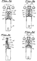
- the tool according to the invention comprises a substantially cylindrical body 10 forming the handle of the tool itself and a part 20 for engagement with/operation of the nut 30 to be screwed/unscrewed.
- the handle 10 has, housed inside it, a motor 11 for operation of a shaft 11a projecting axially from the body 10, which motor is provided with on/off switching means 12 and means 13 for adjusting its speed of rotation.
- Said means for switching it on comprise a switch 12 acting, with a translatory movement, against the thrusting action of a spring 12a which is coaxial with the shaft 11 and which has the function of preventing random and unintentional displacement of the switch with consequent unwanted switching-on of the motor.
- Said switch forms a single body with the external cylindrical casing of the screwing device, thus producing the axial movement of the latter as will be further explained below.
- the motor may be provided with a mixed power supply from the mains and a rechargeable battery which is known per se and therefore not illustrated.
- the part 20 for engaging with and operating the nut 30 comprises a first bevel gearwheel 21a which is mounted on the free end of the shaft 11a and is designed to engage with/operate a corresponding second bevel gearwheel 21b mounted on a pin 21c substantially perpendicular to the axis of the motor shaft 11a.
- a pinion 22 which is designed to engage with and operate two toothed wheels 23 respectively mounted on corresponding pins 23a, on each of which a shaped arm 24 rotating on the associated pin 23a is also mounted.
- the two arms 24 are arranged symmetrically with respect to the longitudinal axis of the tool and shaped so as to form grippers which are kept in the closed condition by a spring 26 arranged between the two arms 25.
- the spring 26 is positioned at the end of the arms 25 opposite to the gripping end, relative to the pin 23a, and is therefore a compression spring which pushes against the arms so as to keep them normally rotated in the closed condition.
- the arms 24 are locked in their working position, engaged with the nut 30, by means of displacement, in the axial direction, of the cylindrical switch 12 which, moving forwards as a result of closing of the starting contact of the motor, comes into abutment against the inner end of the arms 25, preventing the opening rotational movement thereof and thus ensuring a stable grip on the nut.
- Each arm 24 also carries idle rollers 25 on associated pins 25a, which are designed to engage with a corresponding annular seat 32 in the nut 30 so as to allow correct engagement between the parts and facilitate the displacement of the tool in the axial direction together with and in unison with the nut 30 during screwing/unscrewing thereof, as will be further explained below with reference to the description of operation of the tool.
- Fig. 3 shows in schematic form a hydraulic union of the known type comprising a plurality of inlets/outlets provided with a locking nut 30, the operating mode of the tool is as follows:
- the tool according to the invention allows perfect and functional engagement, in the radial direction, with a nut provided with external toothing and how operation of the tool allows screwing/unscrewing of the nut also in the case of frontal and/or perpendicular joining together of parts which prevent the use of normal power-driven tools, frontal access of the latter to the nut not being permitted.
- screwing device also allows rapid and secure tightening of the nuts since the tool may be calibrated so as to provide a predetermined tightening torque which produces the desired engagement, but without causing damage to the individual parts, damage which is particularly serious in the case, for example, of connections of the hydraulic type where even a small deformation of a component may be the cause of leakages from the union.
- toothed wheels 23 may be replaced by rubber-lined rollers 123 which allow screwing/unscrewing of nuts which do not have the said toothing 31.
- an endless belt pulley 223 with a double toothing is provided on the toothed wheels 23 so that the internal toothing receives movement from the toothed wheels themselves and the external toothing transmits the movement to the nut 30.
Landscapes
- Engineering & Computer Science (AREA)
- Mechanical Engineering (AREA)
- Details Of Spanners, Wrenches, And Screw Drivers And Accessories (AREA)
- Dowels (AREA)
Applications Claiming Priority (2)
| Application Number | Priority Date | Filing Date | Title |
|---|---|---|---|
| ITMI972155 | 1997-09-24 | ||
| ITMI972155 IT1295054B1 (it) | 1997-09-24 | 1997-09-24 | Utensile per l'avvitamento/svitamento di dadi dotati di dentatura sulla propria superficie esterna |
Publications (1)
| Publication Number | Publication Date |
|---|---|
| EP0904899A2 true EP0904899A2 (de) | 1999-03-31 |
Family
ID=11377919
Family Applications (1)
| Application Number | Title | Priority Date | Filing Date |
|---|---|---|---|
| EP19980203056 Withdrawn EP0904899A2 (de) | 1997-09-24 | 1998-09-12 | Werkzeug zum Anziehen/Lösen von Muttern deren äussere Oberfläche mit Zähnen versehenen sind |
Country Status (2)
| Country | Link |
|---|---|
| EP (1) | EP0904899A2 (de) |
| IT (1) | IT1295054B1 (de) |
Cited By (4)
| Publication number | Priority date | Publication date | Assignee | Title |
|---|---|---|---|---|
| EP1118434A3 (de) * | 2000-01-20 | 2002-10-30 | Lindner Armaturen GmbH | Vorrichtung zur Verbindung einer Rohrleitung mit einem Rohrleitungselement mittels Klemm- oder Schneidring |
| ITRE20100070A1 (it) * | 2010-09-13 | 2012-03-14 | Casarini Srl | Gruppo per l'avvitamento di corpi filettati |
| EP3055603B1 (de) | 2013-10-11 | 2020-09-16 | Designerscope Limited | Schrankplanierungsvorrichtung |
| US11786035B2 (en) | 2017-09-04 | 2023-10-17 | Designerscope Limited | Cabinet levelling apparatus |
-
1997
- 1997-09-24 IT ITMI972155 patent/IT1295054B1/it active IP Right Grant
-
1998
- 1998-09-12 EP EP19980203056 patent/EP0904899A2/de not_active Withdrawn
Cited By (8)
| Publication number | Priority date | Publication date | Assignee | Title |
|---|---|---|---|---|
| EP1118434A3 (de) * | 2000-01-20 | 2002-10-30 | Lindner Armaturen GmbH | Vorrichtung zur Verbindung einer Rohrleitung mit einem Rohrleitungselement mittels Klemm- oder Schneidring |
| ITRE20100070A1 (it) * | 2010-09-13 | 2012-03-14 | Casarini Srl | Gruppo per l'avvitamento di corpi filettati |
| EP3055603B1 (de) | 2013-10-11 | 2020-09-16 | Designerscope Limited | Schrankplanierungsvorrichtung |
| EP3767151A1 (de) | 2013-10-11 | 2021-01-20 | Designerscope Limited | Schranknivelliervorrichtung |
| EP4089309A1 (de) * | 2013-10-11 | 2022-11-16 | Häfele SE & Co KG | Schranknivelliervorrichtung |
| EP4276235A3 (de) * | 2013-10-11 | 2024-01-10 | Häfele SE & Co KG | Schranknivelliervorrichtung |
| EP3767151B1 (de) | 2013-10-11 | 2024-07-03 | Häfele SE & Co KG | Schranknivelliervorrichtung |
| US11786035B2 (en) | 2017-09-04 | 2023-10-17 | Designerscope Limited | Cabinet levelling apparatus |
Also Published As
| Publication number | Publication date |
|---|---|
| IT1295054B1 (it) | 1999-04-27 |
| ITMI972155A1 (it) | 1999-03-24 |
Similar Documents
| Publication | Publication Date | Title |
|---|---|---|
| US9381625B2 (en) | Electrical wrench | |
| CA1082011A (en) | Torque responsive speed shift mechanism for power tool | |
| US4231270A (en) | Electrically driven fastening appliance | |
| EP0525911B1 (de) | Getriebe eines elektrisch angetriebenen Werkzeuges | |
| US4155278A (en) | Swivel head reaction bar nut runner | |
| CA1097103A (en) | Power-driven drill and screwdriver | |
| US3937036A (en) | Rotary driving tool having a torque responsive clutch | |
| US4106371A (en) | Clamping tool | |
| US4930793A (en) | Keyless chuck | |
| JPH0727121A (ja) | 締付け用ネジ | |
| JP2000506448A (ja) | トルク解放クラッチと調節工具を備えた動力ナットランナー | |
| US8439763B2 (en) | Wedge clutch assembly | |
| JP2000506447A (ja) | 動力ナットランナー | |
| JPH11309677A (ja) | 手持ち電動工具機械 | |
| US20180250803A1 (en) | Speed-changing tool | |
| US6173792B1 (en) | Power-driven screwdriver with torque-dependent release clutch | |
| US4318314A (en) | Ratchet wrench assembly | |
| US4472985A (en) | Fastening tool | |
| US6843141B2 (en) | Hand-held power tool with a torque cut-off device | |
| EP0904899A2 (de) | Werkzeug zum Anziehen/Lösen von Muttern deren äussere Oberfläche mit Zähnen versehenen sind | |
| US2606431A (en) | Adjustable drive clutch for regulating the torque imparted to a driven member | |
| US6899653B2 (en) | Fastener with gear assembly | |
| US4785649A (en) | Tapered thread roll-forming machine | |
| US4727780A (en) | Vehicle-carrying purpose wrench | |
| DE3919648C2 (de) | Winkelschrauber |
Legal Events
| Date | Code | Title | Description |
|---|---|---|---|
| PUAI | Public reference made under article 153(3) epc to a published international application that has entered the european phase |
Free format text: ORIGINAL CODE: 0009012 |
|
| AK | Designated contracting states |
Kind code of ref document: A2 Designated state(s): AT BE CH CY DE DK ES FI FR GB GR IE IT LI LU MC NL PT SE |
|
| AX | Request for extension of the european patent |
Free format text: AL;LT;LV;MK;RO;SI |
|
| STAA | Information on the status of an ep patent application or granted ep patent |
Free format text: STATUS: THE APPLICATION IS DEEMED TO BE WITHDRAWN |
|
| 18D | Application deemed to be withdrawn |
Effective date: 20010403 |