EP0904899A2 - Tool for screwing/unscrewing nuts provided with toothing on their external surface - Google Patents
Tool for screwing/unscrewing nuts provided with toothing on their external surface Download PDFInfo
- Publication number
- EP0904899A2 EP0904899A2 EP19980203056 EP98203056A EP0904899A2 EP 0904899 A2 EP0904899 A2 EP 0904899A2 EP 19980203056 EP19980203056 EP 19980203056 EP 98203056 A EP98203056 A EP 98203056A EP 0904899 A2 EP0904899 A2 EP 0904899A2
- Authority
- EP
- European Patent Office
- Prior art keywords
- nut
- tool according
- arms
- tool
- motor
- Prior art date
- Legal status (The legal status is an assumption and is not a legal conclusion. Google has not performed a legal analysis and makes no representation as to the accuracy of the status listed.)
- Withdrawn
Links
- 230000006835 compression Effects 0.000 claims description 2
- 238000007906 compression Methods 0.000 claims description 2
- 230000005540 biological transmission Effects 0.000 claims 2
- 238000006073 displacement reaction Methods 0.000 description 4
- 238000012423 maintenance Methods 0.000 description 1
- 238000004519 manufacturing process Methods 0.000 description 1
- 230000001681 protective effect Effects 0.000 description 1
Images


Classifications
-
- B—PERFORMING OPERATIONS; TRANSPORTING
- B25—HAND TOOLS; PORTABLE POWER-DRIVEN TOOLS; MANIPULATORS
- B25B—TOOLS OR BENCH DEVICES NOT OTHERWISE PROVIDED FOR, FOR FASTENING, CONNECTING, DISENGAGING OR HOLDING
- B25B21/00—Portable power-driven screw or nut setting or loosening tools; Attachments for drilling apparatus serving the same purpose
- B25B21/002—Portable power-driven screw or nut setting or loosening tools; Attachments for drilling apparatus serving the same purpose for special purposes
-
- B—PERFORMING OPERATIONS; TRANSPORTING
- B25—HAND TOOLS; PORTABLE POWER-DRIVEN TOOLS; MANIPULATORS
- B25B—TOOLS OR BENCH DEVICES NOT OTHERWISE PROVIDED FOR, FOR FASTENING, CONNECTING, DISENGAGING OR HOLDING
- B25B13/00—Spanners; Wrenches
- B25B13/48—Spanners; Wrenches for special purposes
- B25B13/50—Spanners; Wrenches for special purposes for operating on work of special profile, e.g. pipes
- B25B13/5008—Spanners; Wrenches for special purposes for operating on work of special profile, e.g. pipes for operating on pipes or cylindrical objects
- B25B13/5016—Spanners; Wrenches for special purposes for operating on work of special profile, e.g. pipes for operating on pipes or cylindrical objects by externally gripping the pipe
Definitions
- the present invention relates to a tool for screwing/unscrewing nuts provided with a radial toothing on their external surface.
- the tool should be easy and inexpensive to manufacture, consisting of a small number of parts, that it should be easily accessible for any maintenance operations and that it should have small overall dimensions so as to facilitate storage, transportation and use by the user also in difficult conditions.
- a tool for screwing/unscrewing nuts provided with toothing on their external surface, which comprises an operating part and a part for engaging with said nut, said engaging part essentially consisting of two arms which are associated with corresponding means for operating said arms so as to close them in the radial direction onto the nut and means for engagement with and rotational operation of the nut in both directions for screwing/unscrewing thereof.
- the tool according to the invention comprises a substantially cylindrical body 10 forming the handle of the tool itself and a part 20 for engagement with/operation of the nut 30 to be screwed/unscrewed.
- the handle 10 has, housed inside it, a motor 11 for operation of a shaft 11a projecting axially from the body 10, which motor is provided with on/off switching means 12 and means 13 for adjusting its speed of rotation.
- Said means for switching it on comprise a switch 12 acting, with a translatory movement, against the thrusting action of a spring 12a which is coaxial with the shaft 11 and which has the function of preventing random and unintentional displacement of the switch with consequent unwanted switching-on of the motor.
- Said switch forms a single body with the external cylindrical casing of the screwing device, thus producing the axial movement of the latter as will be further explained below.
- the motor may be provided with a mixed power supply from the mains and a rechargeable battery which is known per se and therefore not illustrated.
- the part 20 for engaging with and operating the nut 30 comprises a first bevel gearwheel 21a which is mounted on the free end of the shaft 11a and is designed to engage with/operate a corresponding second bevel gearwheel 21b mounted on a pin 21c substantially perpendicular to the axis of the motor shaft 11a.
- a pinion 22 which is designed to engage with and operate two toothed wheels 23 respectively mounted on corresponding pins 23a, on each of which a shaped arm 24 rotating on the associated pin 23a is also mounted.
- the two arms 24 are arranged symmetrically with respect to the longitudinal axis of the tool and shaped so as to form grippers which are kept in the closed condition by a spring 26 arranged between the two arms 25.
- the spring 26 is positioned at the end of the arms 25 opposite to the gripping end, relative to the pin 23a, and is therefore a compression spring which pushes against the arms so as to keep them normally rotated in the closed condition.
- the arms 24 are locked in their working position, engaged with the nut 30, by means of displacement, in the axial direction, of the cylindrical switch 12 which, moving forwards as a result of closing of the starting contact of the motor, comes into abutment against the inner end of the arms 25, preventing the opening rotational movement thereof and thus ensuring a stable grip on the nut.
- Each arm 24 also carries idle rollers 25 on associated pins 25a, which are designed to engage with a corresponding annular seat 32 in the nut 30 so as to allow correct engagement between the parts and facilitate the displacement of the tool in the axial direction together with and in unison with the nut 30 during screwing/unscrewing thereof, as will be further explained below with reference to the description of operation of the tool.
- Fig. 3 shows in schematic form a hydraulic union of the known type comprising a plurality of inlets/outlets provided with a locking nut 30, the operating mode of the tool is as follows:
- the tool according to the invention allows perfect and functional engagement, in the radial direction, with a nut provided with external toothing and how operation of the tool allows screwing/unscrewing of the nut also in the case of frontal and/or perpendicular joining together of parts which prevent the use of normal power-driven tools, frontal access of the latter to the nut not being permitted.
- screwing device also allows rapid and secure tightening of the nuts since the tool may be calibrated so as to provide a predetermined tightening torque which produces the desired engagement, but without causing damage to the individual parts, damage which is particularly serious in the case, for example, of connections of the hydraulic type where even a small deformation of a component may be the cause of leakages from the union.
- toothed wheels 23 may be replaced by rubber-lined rollers 123 which allow screwing/unscrewing of nuts which do not have the said toothing 31.
- an endless belt pulley 223 with a double toothing is provided on the toothed wheels 23 so that the internal toothing receives movement from the toothed wheels themselves and the external toothing transmits the movement to the nut 30.
Landscapes
- Engineering & Computer Science (AREA)
- Mechanical Engineering (AREA)
- Dowels (AREA)
- Details Of Spanners, Wrenches, And Screw Drivers And Accessories (AREA)
Abstract
Tool for screwing/unscrewing nuts (30) provided with
toothing (31) on their external surface, which comprises
an operating part (10) and a part (20) for engaging with
said nut (30), said engaging part essentially consisting
of two arms (24) which are associated with corresponding
means (26) for operating said arms so as to close them in
the radial direction onto the nut (30) and means
(23;123;223) for engagement with and rotational operation
of the nut (30) in both directions for
screwing/unscrewing thereof.
Description
- The present invention relates to a tool for screwing/unscrewing nuts provided with a radial toothing on their external surface.
- It is known in the technical sector relating to the connection of pipes to threaded connections of hydraulic equipment and the like that there exists the need to screw onto the threading of the said connection the locking nut of the union which provides the sealed connection between the two parts.
- It is also known that tightening of the nut of the union cannot be performed by means of power-driven tightening tools, of the screwing and similar type, since access to the nut with the tool is possible only in a radial direction and not in the axial direction which is prevented by the presence of the pipe, on the one hand, and the connection itself, on the other hand.
- An Italian patent application in the name of the same Applicant describes a locking nut provided with a radial toothing formed on its external surface and suitable for radial engagement with a corresponding tightening tool. The technical problem which is posed, therefore, is that of providing a manual or power-driven tool, of the screwing/unscrewing type, suitable for engagement in the radial direction with locking nuts for connection elements of parts to be joined together in frontal and/or perpendicular directions such as, for example, those of the unions for the sealed connection of pipes with threaded connections of hydraulic, pneumatic and similar equipment.
- Within the scope of this problem a further requirement is that the tool should be easy and inexpensive to manufacture, consisting of a small number of parts, that it should be easily accessible for any maintenance operations and that it should have small overall dimensions so as to facilitate storage, transportation and use by the user also in difficult conditions.
- These technical problems are solved according to the present invention by a tool for screwing/unscrewing nuts provided with toothing on their external surface, which comprises an operating part and a part for engaging with said nut, said engaging part essentially consisting of two arms which are associated with corresponding means for operating said arms so as to close them in the radial direction onto the nut and means for engagement with and rotational operation of the nut in both directions for screwing/unscrewing thereof.
- Further details may be obtained from the following description of a non-limiting example of embodiment of the invention provided with reference to the accompanying drawings, in which:
- Figure 1 shows a partially sectioned front view of a first example of embodiment of the tool according to the invention;
- Figure 2 shows a partially sectioned side view of the tool according to Fig. 1;
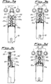
- Figs. 3a-3d show the sequence for gripping and screwing, by means of the tool according to the invention, a nut with an external toothing;
- Figure 4 shows a first alternative example of embodiment of the tool according to the invention; and
- Figure 5 shows a second alternative example of embodiment of the tool according to the invention.
- As illustrated in Figs. 1 and 2, the tool according to the invention comprises a substantially
cylindrical body 10 forming the handle of the tool itself and apart 20 for engagement with/operation of thenut 30 to be screwed/unscrewed. - The
handle 10 has, housed inside it, amotor 11 for operation of ashaft 11a projecting axially from thebody 10, which motor is provided with on/off switching means 12 and means 13 for adjusting its speed of rotation. - Said means for switching it on comprise a
switch 12 acting, with a translatory movement, against the thrusting action of aspring 12a which is coaxial with theshaft 11 and which has the function of preventing random and unintentional displacement of the switch with consequent unwanted switching-on of the motor. - Said switch forms a single body with the external cylindrical casing of the screwing device, thus producing the axial movement of the latter as will be further explained below.
- The motor may be provided with a mixed power supply from the mains and a rechargeable battery which is known per se and therefore not illustrated.
- The
part 20 for engaging with and operating thenut 30 comprises afirst bevel gearwheel 21a which is mounted on the free end of theshaft 11a and is designed to engage with/operate a corresponding second bevel gearwheel 21b mounted on apin 21c substantially perpendicular to the axis of themotor shaft 11a. - On the
same pin 21c there is also mounted apinion 22 which is designed to engage with and operate twotoothed wheels 23 respectively mounted oncorresponding pins 23a, on each of which ashaped arm 24 rotating on the associatedpin 23a is also mounted. - As shown, the two
arms 24 are arranged symmetrically with respect to the longitudinal axis of the tool and shaped so as to form grippers which are kept in the closed condition by aspring 26 arranged between the twoarms 25. In the example shown thespring 26 is positioned at the end of thearms 25 opposite to the gripping end, relative to thepin 23a, and is therefore a compression spring which pushes against the arms so as to keep them normally rotated in the closed condition. - The
arms 24 are locked in their working position, engaged with thenut 30, by means of displacement, in the axial direction, of thecylindrical switch 12 which, moving forwards as a result of closing of the starting contact of the motor, comes into abutment against the inner end of thearms 25, preventing the opening rotational movement thereof and thus ensuring a stable grip on the nut. - However, it is obviously within the competence of a person skilled in the art to envisage equivalent variations in the arrangement of the spring and its action, provided that the operation described above is maintained.
- Each
arm 24 also carriesidle rollers 25 on associated pins 25a, which are designed to engage with a correspondingannular seat 32 in thenut 30 so as to allow correct engagement between the parts and facilitate the displacement of the tool in the axial direction together with and in unison with thenut 30 during screwing/unscrewing thereof, as will be further explained below with reference to the description of operation of the tool. - The
part 20 engaging with thenut 30, finally, is completed by a protection and safety cover 26' which encloses all the moving parts and leaves exposed only the parts of thearms 24 which are intended to engage with thenut 30. - As illustrated in sequence in Fig. 3, which shows in schematic form a hydraulic union of the known type comprising a plurality of inlets/outlets provided with a
locking nut 30, the operating mode of the tool is as follows: - keeping the actuating
motor 11 switched off, the grippingarms 24 are moved towards the nut 30 (Fig. 3a); - exerting a pressure on the tool in the axial direction
causes widening of the
arms 24 and their engagement, in the radial direction, with thenut 30 so that thearms 24 are inserted into the correspondingannular seat 32 of thenut 30 and thetoothed wheels 23 mesh with theexternal toothing 31 of the nut (Figs. 3b,3c); - at this point the motor is actuated by means of the
switch 12, causing screwing/unscrewing of thenut 30 of the union, by means of the action of the tool which is able to operate with constant characteristics also during displacement of the nut in the axial direction due to screwing/unscrewing thereof on the threading of the fixed connection, owing to engagement of therollers 25 of thearms 24 with theannular seat 32 of thenut 30. - It is therefore obvious how the tool according to the invention allows perfect and functional engagement, in the radial direction, with a nut provided with external toothing and how operation of the tool allows screwing/unscrewing of the nut also in the case of frontal and/or perpendicular joining together of parts which prevent the use of normal power-driven tools, frontal access of the latter to the nut not being permitted.
- In addition to this, use of the screwing device according to the invention also allows rapid and secure tightening of the nuts since the tool may be calibrated so as to provide a predetermined tightening torque which produces the desired engagement, but without causing damage to the individual parts, damage which is particularly serious in the case, for example, of connections of the hydraulic type where even a small deformation of a component may be the cause of leakages from the union.
- Many variations of the individual parts which make up the tool may be introduced without departing from the protective scope of the present patent.
- For example, it is envisaged (Fig. 4) that the
toothed wheels 23 may be replaced by rubber-linedrollers 123 which allow screwing/unscrewing of nuts which do not have the said toothing 31. - In a further embodiment, an
endless belt pulley 223 with a double toothing is provided on thetoothed wheels 23 so that the internal toothing receives movement from the toothed wheels themselves and the external toothing transmits the movement to thenut 30.
Claims (19)
- Tool for screwing/unscrewing nuts (30) provided with toothing (31) on their external surface, which comprises an operating part (10) and a part (20) for engaging with said nut (30), characterized in that said engaging part (20) essentially consists of two arms (24) which are associated with corresponding means (26) for operating said arms so as to close them in the radial direction onto the nut (30) and means (23;123;223) for engagement with and rotational operation of the nut (30) in both directions for screwing/unscrewing thereof.
- Tool according to Claim 1, characterized in that said arms (24) are arranged symmetrically with respect to the longitudinal axis of the tool so as to form grippers which can be clamped onto the nut (30).
- Tool according to Claim 1, characterized in that said arms (24) rotate about an associated support pin (23a) fixed to the tool.
- Tool according to Claim 1, characterized in that said means for clamping the arms (24) onto the nut (30) are resilient means (26).
- Tool according to Claims 1 and 4, characterized in that said resilient means consist of a compression spring arranged between the arms themselves.
- Tool according to Claim 1, characterized in that it comprises means (12) for locking the arms (24) upon start-up of the motor of the tool.
- Tool according to Claim 6, characterized in that said means (12) for locking the arms (24) consist of a cylindrical casing integral with the switch for switching the motor on/off and movable axially therewith.
- Tool according to Claim 1, characterized in that said arms (24) carry rollers (25) designed to engage with an associated annular seat (32) in the nut (30).
- Tool according to Claim 1, characterized in that said means (23;123;223) for rotational operation of the nut (30) are coaxially mounted on each fixed pin (23a) supporting the arms.
- Tool according to Claim 1, characterized in that said means for rotational operation of the nut (30) consist of a pair of toothed wheels (23).
- Tool according to Claims 1 and 7, characterized in that said means for rotational operation of the nut (30) consist of a pair of toothed wheels (23), the part of which engaging with the nut consists of a rubberized covering (123).
- Tool according to Claim 1, characterized in that said means for operational rotation of the nut (30) consist of a pair of toothed wheels (23), the part of which engaging with the nut consists of a toothed belt (223) with a double toothing for receiving/transmitting the movement.
- Tool according to Claim 1, characterized in that said part (10) for generating the movement for operation of the nut (30) comprises at least one pinion (22) for operation and synchronization of the toothed wheels (23) associated with a bevel gearwheel (21a,21b) for transmission of the movement from the shaft (11a) of a motor (11) to the pinion (22) itself.
- Tool according to Claim 1, characterized in that said shaft of the motor (11) is arranged in a direction substantially parallel to the longitudinal axis of the tool.
- Tool according to Claim 1, characterized in that the fixed pins (21c,23a) supporting the gearwheels (22,23) for transmission of the movement to the nut (30) are substantially perpendicular to the motor shaft (11a).
- Tool according to Claim 1, characterized in that the motor (11) is of the variable-speed type.
- Tool according to Claims 1 and 14, characterized in that means (13) for adjusting the speed of rotation of the motor are provided.
- Tool according to Claim 1, characterized in that it comprises means (12) for switching the motor (11) on/off, which are associated with a safety device (12a).
- Tool according to Claims 1 and 18, characterized in that said safety device consists of a resilient element (12a) coaxial with the motor shaft (11a) and acting against said on/off switching means (12).
Applications Claiming Priority (2)
| Application Number | Priority Date | Filing Date | Title |
|---|---|---|---|
| ITMI972155 IT1295054B1 (en) | 1997-09-24 | 1997-09-24 | TOOL FOR SCREWING / UNSCREWING NUTS EQUIPPED WITH TOOTHING ON ITS OUTER SURFACE |
| ITMI972155 | 1997-09-24 |
Publications (1)
| Publication Number | Publication Date |
|---|---|
| EP0904899A2 true EP0904899A2 (en) | 1999-03-31 |
Family
ID=11377919
Family Applications (1)
| Application Number | Title | Priority Date | Filing Date |
|---|---|---|---|
| EP19980203056 Withdrawn EP0904899A2 (en) | 1997-09-24 | 1998-09-12 | Tool for screwing/unscrewing nuts provided with toothing on their external surface |
Country Status (2)
| Country | Link |
|---|---|
| EP (1) | EP0904899A2 (en) |
| IT (1) | IT1295054B1 (en) |
Cited By (4)
| Publication number | Priority date | Publication date | Assignee | Title |
|---|---|---|---|---|
| EP1118434A3 (en) * | 2000-01-20 | 2002-10-30 | Lindner Armaturen GmbH | Device for connecting a pipe with a tubing element by crimping ring or bite ring |
| ITRE20100070A1 (en) * | 2010-09-13 | 2012-03-14 | Casarini Srl | GROUP FOR THE SCREWING OF THREADED BODIES |
| EP3055603B1 (en) | 2013-10-11 | 2020-09-16 | Designerscope Limited | Cabinet levelling apparatus |
| US11786035B2 (en) | 2017-09-04 | 2023-10-17 | Designerscope Limited | Cabinet levelling apparatus |
-
1997
- 1997-09-24 IT ITMI972155 patent/IT1295054B1/en active IP Right Grant
-
1998
- 1998-09-12 EP EP19980203056 patent/EP0904899A2/en not_active Withdrawn
Cited By (8)
| Publication number | Priority date | Publication date | Assignee | Title |
|---|---|---|---|---|
| EP1118434A3 (en) * | 2000-01-20 | 2002-10-30 | Lindner Armaturen GmbH | Device for connecting a pipe with a tubing element by crimping ring or bite ring |
| ITRE20100070A1 (en) * | 2010-09-13 | 2012-03-14 | Casarini Srl | GROUP FOR THE SCREWING OF THREADED BODIES |
| EP3055603B1 (en) | 2013-10-11 | 2020-09-16 | Designerscope Limited | Cabinet levelling apparatus |
| EP3767151A1 (en) | 2013-10-11 | 2021-01-20 | Designerscope Limited | Cabinet levelling apparatus |
| EP4089309A1 (en) * | 2013-10-11 | 2022-11-16 | Häfele SE & Co KG | Cabinet levelling apparatus |
| EP4276235A3 (en) * | 2013-10-11 | 2024-01-10 | Häfele SE & Co KG | Cabinet levelling apparatus |
| EP3767151B1 (en) | 2013-10-11 | 2024-07-03 | Häfele SE & Co KG | Cabinet levelling apparatus |
| US11786035B2 (en) | 2017-09-04 | 2023-10-17 | Designerscope Limited | Cabinet levelling apparatus |
Also Published As
| Publication number | Publication date |
|---|---|
| ITMI972155A1 (en) | 1999-03-24 |
| IT1295054B1 (en) | 1999-04-27 |
Similar Documents
| Publication | Publication Date | Title |
|---|---|---|
| US9381625B2 (en) | Electrical wrench | |
| US4215594A (en) | Torque responsive speed shift mechanism for power tool | |
| US4231270A (en) | Electrically driven fastening appliance | |
| US4448098A (en) | Electrically driven screw-driver | |
| EP0525911B1 (en) | Transmission for electrically driven tool | |
| US4155278A (en) | Swivel head reaction bar nut runner | |
| US5356350A (en) | Motor-driven screwdriver with variable torque setting for equal torques regardless or countertorques by fasteners | |
| CA1097103A (en) | Power-driven drill and screwdriver | |
| US3937036A (en) | Rotary driving tool having a torque responsive clutch | |
| US4930793A (en) | Keyless chuck | |
| JP2000506448A (en) | Power nutrunner with torque release clutch and adjustment tool | |
| US10751869B2 (en) | Speed-changing tool | |
| JP2000506447A (en) | Power nutrunner | |
| JPH11309677A (en) | Portable power tool | |
| US6173792B1 (en) | Power-driven screwdriver with torque-dependent release clutch | |
| US20110214960A1 (en) | Wedge clutch assembly | |
| US4318314A (en) | Ratchet wrench assembly | |
| US6843141B2 (en) | Hand-held power tool with a torque cut-off device | |
| EP0904899A2 (en) | Tool for screwing/unscrewing nuts provided with toothing on their external surface | |
| US2606431A (en) | Adjustable drive clutch for regulating the torque imparted to a driven member | |
| US6899653B2 (en) | Fastener with gear assembly | |
| US4785649A (en) | Tapered thread roll-forming machine | |
| US4727780A (en) | Vehicle-carrying purpose wrench | |
| DE3919648C2 (en) | Angle screwdriver | |
| EP0088836B1 (en) | An electrically driven screw-driver |
Legal Events
| Date | Code | Title | Description |
|---|---|---|---|
| PUAI | Public reference made under article 153(3) epc to a published international application that has entered the european phase |
Free format text: ORIGINAL CODE: 0009012 |
|
| AK | Designated contracting states |
Kind code of ref document: A2 Designated state(s): AT BE CH CY DE DK ES FI FR GB GR IE IT LI LU MC NL PT SE |
|
| AX | Request for extension of the european patent |
Free format text: AL;LT;LV;MK;RO;SI |
|
| STAA | Information on the status of an ep patent application or granted ep patent |
Free format text: STATUS: THE APPLICATION IS DEEMED TO BE WITHDRAWN |
|
| 18D | Application deemed to be withdrawn |
Effective date: 20010403 |