EP0904843B1 - Spraying apparatus for artificial hair augmenting agent - Google Patents
Spraying apparatus for artificial hair augmenting agent Download PDFInfo
- Publication number
- EP0904843B1 EP0904843B1 EP98907244A EP98907244A EP0904843B1 EP 0904843 B1 EP0904843 B1 EP 0904843B1 EP 98907244 A EP98907244 A EP 98907244A EP 98907244 A EP98907244 A EP 98907244A EP 0904843 B1 EP0904843 B1 EP 0904843B1
- Authority
- EP
- European Patent Office
- Prior art keywords
- increasing material
- container
- pseudo hair
- hair increasing
- injection
- Prior art date
- Legal status (The legal status is an assumption and is not a legal conclusion. Google has not performed a legal analysis and makes no representation as to the accuracy of the status listed.)
- Expired - Lifetime
Links
- 210000004209 hair Anatomy 0.000 title claims description 243
- 238000005507 spraying Methods 0.000 title claims description 62
- 230000003190 augmentative effect Effects 0.000 title 1
- 230000001965 increasing effect Effects 0.000 claims description 190
- 239000000463 material Substances 0.000 claims description 190
- 238000002347 injection Methods 0.000 claims description 157
- 239000007924 injection Substances 0.000 claims description 157
- 239000003380 propellant Substances 0.000 claims description 79
- 239000000203 mixture Substances 0.000 claims description 46
- 239000007788 liquid Substances 0.000 claims description 29
- 239000004744 fabric Substances 0.000 claims description 21
- 239000000843 powder Substances 0.000 claims description 17
- 238000007599 discharging Methods 0.000 claims description 7
- 239000007789 gas Substances 0.000 description 92
- 239000000443 aerosol Substances 0.000 description 31
- 210000003128 head Anatomy 0.000 description 25
- 230000003247 decreasing effect Effects 0.000 description 16
- 238000003860 storage Methods 0.000 description 15
- LCGLNKUTAGEVQW-UHFFFAOYSA-N Dimethyl ether Chemical compound COC LCGLNKUTAGEVQW-UHFFFAOYSA-N 0.000 description 12
- LFQSCWFLJHTTHZ-UHFFFAOYSA-N Ethanol Chemical compound CCO LFQSCWFLJHTTHZ-UHFFFAOYSA-N 0.000 description 12
- 238000009472 formulation Methods 0.000 description 9
- 230000000694 effects Effects 0.000 description 8
- 238000000034 method Methods 0.000 description 8
- 239000000853 adhesive Substances 0.000 description 7
- 230000001070 adhesive effect Effects 0.000 description 7
- 210000004761 scalp Anatomy 0.000 description 6
- 238000010276 construction Methods 0.000 description 5
- 229920001577 copolymer Polymers 0.000 description 5
- 239000000835 fiber Substances 0.000 description 5
- 230000002093 peripheral effect Effects 0.000 description 5
- 238000003825 pressing Methods 0.000 description 5
- 230000003068 static effect Effects 0.000 description 5
- 239000003915 liquefied petroleum gas Substances 0.000 description 4
- 239000002304 perfume Substances 0.000 description 4
- 229920000642 polymer Polymers 0.000 description 4
- 239000008213 purified water Substances 0.000 description 4
- -1 substitute freon Substances 0.000 description 4
- XLYOFNOQVPJJNP-UHFFFAOYSA-N water Chemical compound O XLYOFNOQVPJJNP-UHFFFAOYSA-N 0.000 description 4
- 229920001971 elastomer Polymers 0.000 description 3
- 238000003780 insertion Methods 0.000 description 3
- 230000037431 insertion Effects 0.000 description 3
- 239000006210 lotion Substances 0.000 description 3
- 238000000926 separation method Methods 0.000 description 3
- 239000007921 spray Substances 0.000 description 3
- 230000001502 supplementing effect Effects 0.000 description 3
- 229940098465 tincture Drugs 0.000 description 3
- YBJHBAHKTGYVGT-ZKWXMUAHSA-N (+)-Biotin Chemical compound N1C(=O)N[C@@H]2[C@H](CCCCC(=O)O)SC[C@@H]21 YBJHBAHKTGYVGT-ZKWXMUAHSA-N 0.000 description 2
- NOOLISFMXDJSKH-KXUCPTDWSA-N (-)-Menthol Chemical compound CC(C)[C@@H]1CC[C@@H](C)C[C@H]1O NOOLISFMXDJSKH-KXUCPTDWSA-N 0.000 description 2
- FFJCNSLCJOQHKM-CLFAGFIQSA-N (z)-1-[(z)-octadec-9-enoxy]octadec-9-ene Chemical compound CCCCCCCC\C=C/CCCCCCCCOCCCCCCCC\C=C/CCCCCCCC FFJCNSLCJOQHKM-CLFAGFIQSA-N 0.000 description 2
- GVJHHUAWPYXKBD-UHFFFAOYSA-N (±)-α-Tocopherol Chemical compound OC1=C(C)C(C)=C2OC(CCCC(C)CCCC(C)CCCC(C)C)(C)CCC2=C1C GVJHHUAWPYXKBD-UHFFFAOYSA-N 0.000 description 2
- MPDGHEJMBKOTSU-YKLVYJNSSA-N 18beta-glycyrrhetic acid Chemical compound C([C@H]1C2=CC(=O)[C@H]34)[C@@](C)(C(O)=O)CC[C@]1(C)CC[C@@]2(C)[C@]4(C)CC[C@@H]1[C@]3(C)CC[C@H](O)C1(C)C MPDGHEJMBKOTSU-YKLVYJNSSA-N 0.000 description 2
- 239000004925 Acrylic resin Substances 0.000 description 2
- 229920000178 Acrylic resin Polymers 0.000 description 2
- 102000008186 Collagen Human genes 0.000 description 2
- 108010035532 Collagen Proteins 0.000 description 2
- RTZKZFJDLAIYFH-UHFFFAOYSA-N Diethyl ether Chemical compound CCOCC RTZKZFJDLAIYFH-UHFFFAOYSA-N 0.000 description 2
- VEXZGXHMUGYJMC-UHFFFAOYSA-N Hydrochloric acid Chemical compound Cl VEXZGXHMUGYJMC-UHFFFAOYSA-N 0.000 description 2
- TWRXJAOTZQYOKJ-UHFFFAOYSA-L Magnesium chloride Chemical compound [Mg+2].[Cl-].[Cl-] TWRXJAOTZQYOKJ-UHFFFAOYSA-L 0.000 description 2
- CSNNHWWHGAXBCP-UHFFFAOYSA-L Magnesium sulfate Chemical compound [Mg+2].[O-][S+2]([O-])([O-])[O-] CSNNHWWHGAXBCP-UHFFFAOYSA-L 0.000 description 2
- WHNWPMSKXPGLAX-UHFFFAOYSA-N N-Vinyl-2-pyrrolidone Chemical compound C=CN1CCCC1=O WHNWPMSKXPGLAX-UHFFFAOYSA-N 0.000 description 2
- 229920003171 Poly (ethylene oxide) Polymers 0.000 description 2
- 239000004372 Polyvinyl alcohol Substances 0.000 description 2
- ATUOYWHBWRKTHZ-UHFFFAOYSA-N Propane Chemical compound CCC ATUOYWHBWRKTHZ-UHFFFAOYSA-N 0.000 description 2
- FAPWRFPIFSIZLT-UHFFFAOYSA-M Sodium chloride Chemical compound [Na+].[Cl-] FAPWRFPIFSIZLT-UHFFFAOYSA-M 0.000 description 2
- 241001530209 Swertia Species 0.000 description 2
- 229920006318 anionic polymer Polymers 0.000 description 2
- FUWUEFKEXZQKKA-UHFFFAOYSA-N beta-thujaplicin Chemical compound CC(C)C=1C=CC=C(O)C(=O)C=1 FUWUEFKEXZQKKA-UHFFFAOYSA-N 0.000 description 2
- 229920006317 cationic polymer Polymers 0.000 description 2
- 229920001436 collagen Polymers 0.000 description 2
- 238000007906 compression Methods 0.000 description 2
- 230000006835 compression Effects 0.000 description 2
- 239000006185 dispersion Substances 0.000 description 2
- 239000000839 emulsion Substances 0.000 description 2
- 150000004676 glycans Chemical class 0.000 description 2
- 230000037308 hair color Effects 0.000 description 2
- 230000001788 irregular Effects 0.000 description 2
- NNPPMTNAJDCUHE-UHFFFAOYSA-N isobutane Chemical compound CC(C)C NNPPMTNAJDCUHE-UHFFFAOYSA-N 0.000 description 2
- 238000004519 manufacturing process Methods 0.000 description 2
- 229920000191 poly(N-vinyl pyrrolidone) Polymers 0.000 description 2
- 229920001282 polysaccharide Polymers 0.000 description 2
- 239000005017 polysaccharide Substances 0.000 description 2
- 229920002451 polyvinyl alcohol Polymers 0.000 description 2
- 229920000036 polyvinylpyrrolidone Polymers 0.000 description 2
- 239000001267 polyvinylpyrrolidone Substances 0.000 description 2
- 235000013855 polyvinylpyrrolidone Nutrition 0.000 description 2
- 235000002639 sodium chloride Nutrition 0.000 description 2
- 239000000243 solution Substances 0.000 description 2
- 239000000126 substance Substances 0.000 description 2
- 229940117958 vinyl acetate Drugs 0.000 description 2
- 239000002699 waste material Substances 0.000 description 2
- DNXHEGUUPJUMQT-UHFFFAOYSA-N (+)-estrone Natural products OC1=CC=C2C3CCC(C)(C(CC4)=O)C4C3CCC2=C1 DNXHEGUUPJUMQT-UHFFFAOYSA-N 0.000 description 1
- MTCFGRXMJLQNBG-REOHCLBHSA-N (2S)-2-Amino-3-hydroxypropansäure Chemical compound OC[C@H](N)C(O)=O MTCFGRXMJLQNBG-REOHCLBHSA-N 0.000 description 1
- MRAMPOPITCOOIN-VIFPVBQESA-N (2r)-n-(3-ethoxypropyl)-2,4-dihydroxy-3,3-dimethylbutanamide Chemical compound CCOCCCNC(=O)[C@H](O)C(C)(C)CO MRAMPOPITCOOIN-VIFPVBQESA-N 0.000 description 1
- DSSYKIVIOFKYAU-XCBNKYQSSA-N (R)-camphor Chemical compound C1C[C@@]2(C)C(=O)C[C@@H]1C2(C)C DSSYKIVIOFKYAU-XCBNKYQSSA-N 0.000 description 1
- LVGUZGTVOIAKKC-UHFFFAOYSA-N 1,1,1,2-tetrafluoroethane Chemical compound FCC(F)(F)F LVGUZGTVOIAKKC-UHFFFAOYSA-N 0.000 description 1
- BOSAWIQFTJIYIS-UHFFFAOYSA-N 1,1,1-trichloro-2,2,2-trifluoroethane Chemical compound FC(F)(F)C(Cl)(Cl)Cl BOSAWIQFTJIYIS-UHFFFAOYSA-N 0.000 description 1
- UJPMYEOUBPIPHQ-UHFFFAOYSA-N 1,1,1-trifluoroethane Chemical compound CC(F)(F)F UJPMYEOUBPIPHQ-UHFFFAOYSA-N 0.000 description 1
- NPNPZTNLOVBDOC-UHFFFAOYSA-N 1,1-difluoroethane Chemical compound CC(F)F NPNPZTNLOVBDOC-UHFFFAOYSA-N 0.000 description 1
- DDMOUSALMHHKOS-UHFFFAOYSA-N 1,2-dichloro-1,1,2,2-tetrafluoroethane Chemical compound FC(F)(Cl)C(F)(F)Cl DDMOUSALMHHKOS-UHFFFAOYSA-N 0.000 description 1
- BFPYWIDHMRZLRN-UHFFFAOYSA-N 17alpha-ethynyl estradiol Natural products OC1=CC=C2C3CCC(C)(C(CC4)(O)C#C)C4C3CCC2=C1 BFPYWIDHMRZLRN-UHFFFAOYSA-N 0.000 description 1
- VOXZDWNPVJITMN-ZBRFXRBCSA-N 17β-estradiol Chemical compound OC1=CC=C2[C@H]3CC[C@](C)([C@H](CC4)O)[C@@H]4[C@@H]3CCC2=C1 VOXZDWNPVJITMN-ZBRFXRBCSA-N 0.000 description 1
- VFKZECOCJCGZQK-UHFFFAOYSA-M 3-hydroxypropyl(trimethyl)azanium;chloride Chemical compound [Cl-].C[N+](C)(C)CCCO VFKZECOCJCGZQK-UHFFFAOYSA-M 0.000 description 1
- 229920000856 Amylose Polymers 0.000 description 1
- 240000004160 Capsicum annuum Species 0.000 description 1
- 235000008534 Capsicum annuum var annuum Nutrition 0.000 description 1
- 235000007862 Capsicum baccatum Nutrition 0.000 description 1
- 229920000049 Carbon (fiber) Polymers 0.000 description 1
- 229920002134 Carboxymethyl cellulose Polymers 0.000 description 1
- 229920002101 Chitin Polymers 0.000 description 1
- VEXZGXHMUGYJMC-UHFFFAOYSA-M Chloride anion Chemical compound [Cl-] VEXZGXHMUGYJMC-UHFFFAOYSA-M 0.000 description 1
- VOPWNXZWBYDODV-UHFFFAOYSA-N Chlorodifluoromethane Chemical compound FC(F)Cl VOPWNXZWBYDODV-UHFFFAOYSA-N 0.000 description 1
- 241000723346 Cinnamomum camphora Species 0.000 description 1
- 229920000742 Cotton Polymers 0.000 description 1
- ZAKOWWREFLAJOT-CEFNRUSXSA-N D-alpha-tocopherylacetate Chemical compound CC(=O)OC1=C(C)C(C)=C2O[C@@](CCC[C@H](C)CCC[C@H](C)CCCC(C)C)(C)CCC2=C1C ZAKOWWREFLAJOT-CEFNRUSXSA-N 0.000 description 1
- 239000011626 DL-alpha-tocopherylacetate Substances 0.000 description 1
- 235000001809 DL-alpha-tocopherylacetate Nutrition 0.000 description 1
- 229920001353 Dextrin Polymers 0.000 description 1
- 239000004338 Dichlorodifluoromethane Substances 0.000 description 1
- DNXHEGUUPJUMQT-CBZIJGRNSA-N Estrone Chemical compound OC1=CC=C2[C@H]3CC[C@](C)(C(CC4)=O)[C@@H]4[C@@H]3CCC2=C1 DNXHEGUUPJUMQT-CBZIJGRNSA-N 0.000 description 1
- BFPYWIDHMRZLRN-SLHNCBLASA-N Ethinyl estradiol Chemical compound OC1=CC=C2[C@H]3CC[C@](C)([C@](CC4)(O)C#C)[C@@H]4[C@@H]3CCC2=C1 BFPYWIDHMRZLRN-SLHNCBLASA-N 0.000 description 1
- 239000006000 Garlic extract Substances 0.000 description 1
- 241001071795 Gentiana Species 0.000 description 1
- MPDGHEJMBKOTSU-UHFFFAOYSA-N Glycyrrhetinsaeure Natural products C12C(=O)C=C3C4CC(C)(C(O)=O)CCC4(C)CCC3(C)C1(C)CCC1C2(C)CCC(O)C1(C)C MPDGHEJMBKOTSU-UHFFFAOYSA-N 0.000 description 1
- 241000202807 Glycyrrhiza Species 0.000 description 1
- BIVBRWYINDPWKA-VLQRKCJKSA-L Glycyrrhizinate dipotassium Chemical compound [K+].[K+].O([C@@H]1[C@@H](O)[C@H](O)[C@H](O[C@@H]1O[C@H]1CC[C@]2(C)[C@H]3C(=O)C=C4[C@@H]5C[C@](C)(CC[C@@]5(CC[C@@]4(C)[C@]3(C)CC[C@H]2C1(C)C)C)C(O)=O)C([O-])=O)[C@@H]1O[C@H](C([O-])=O)[C@@H](O)[C@H](O)[C@H]1O BIVBRWYINDPWKA-VLQRKCJKSA-L 0.000 description 1
- 229920000663 Hydroxyethyl cellulose Polymers 0.000 description 1
- 239000004354 Hydroxyethyl cellulose Substances 0.000 description 1
- ROHFNLRQFUQHCH-YFKPBYRVSA-N L-leucine Chemical compound CC(C)C[C@H](N)C(O)=O ROHFNLRQFUQHCH-YFKPBYRVSA-N 0.000 description 1
- FFEARJCKVFRZRR-BYPYZUCNSA-N L-methionine Chemical compound CSCC[C@H](N)C(O)=O FFEARJCKVFRZRR-BYPYZUCNSA-N 0.000 description 1
- QIVBCDIJIAJPQS-VIFPVBQESA-N L-tryptophane Chemical compound C1=CC=C2C(C[C@H](N)C(O)=O)=CNC2=C1 QIVBCDIJIAJPQS-VIFPVBQESA-N 0.000 description 1
- ROHFNLRQFUQHCH-UHFFFAOYSA-N Leucine Natural products CC(C)CC(N)C(O)=O ROHFNLRQFUQHCH-UHFFFAOYSA-N 0.000 description 1
- 241001071917 Lithospermum Species 0.000 description 1
- ZFMITUMMTDLWHR-UHFFFAOYSA-N Minoxidil Chemical compound NC1=[N+]([O-])C(N)=CC(N2CCCCC2)=N1 ZFMITUMMTDLWHR-UHFFFAOYSA-N 0.000 description 1
- PVNIIMVLHYAWGP-UHFFFAOYSA-N Niacin Chemical compound OC(=O)C1=CC=CN=C1 PVNIIMVLHYAWGP-UHFFFAOYSA-N 0.000 description 1
- 239000004677 Nylon Substances 0.000 description 1
- MTCFGRXMJLQNBG-UHFFFAOYSA-N Serine Natural products OCC(N)C(O)=O MTCFGRXMJLQNBG-UHFFFAOYSA-N 0.000 description 1
- VYPSYNLAJGMNEJ-UHFFFAOYSA-N Silicium dioxide Chemical compound O=[Si]=O VYPSYNLAJGMNEJ-UHFFFAOYSA-N 0.000 description 1
- 239000004115 Sodium Silicate Substances 0.000 description 1
- PMZURENOXWZQFD-UHFFFAOYSA-L Sodium Sulfate Chemical compound [Na+].[Na+].[O-]S([O-])(=O)=O PMZURENOXWZQFD-UHFFFAOYSA-L 0.000 description 1
- 229920002472 Starch Polymers 0.000 description 1
- QIVBCDIJIAJPQS-UHFFFAOYSA-N Tryptophan Natural products C1=CC=C2C(CC(N)C(O)=O)=CNC2=C1 QIVBCDIJIAJPQS-UHFFFAOYSA-N 0.000 description 1
- 239000006035 Tryptophane Substances 0.000 description 1
- 229920002978 Vinylon Polymers 0.000 description 1
- 229930003427 Vitamin E Natural products 0.000 description 1
- 244000273928 Zingiber officinale Species 0.000 description 1
- 235000006886 Zingiber officinale Nutrition 0.000 description 1
- 230000003213 activating effect Effects 0.000 description 1
- 125000005250 alkyl acrylate group Chemical group 0.000 description 1
- 229940069521 aloe extract Drugs 0.000 description 1
- SOGAXMICEFXMKE-UHFFFAOYSA-N alpha-Methyl-n-butyl acrylate Natural products CCCCOC(=O)C(C)=C SOGAXMICEFXMKE-UHFFFAOYSA-N 0.000 description 1
- TUFYVOCKVJOUIR-UHFFFAOYSA-N alpha-Thujaplicin Natural products CC(C)C=1C=CC=CC(=O)C=1O TUFYVOCKVJOUIR-UHFFFAOYSA-N 0.000 description 1
- 150000001413 amino acids Chemical class 0.000 description 1
- 239000002280 amphoteric surfactant Substances 0.000 description 1
- 239000001180 angelica archangelica l. root extract Substances 0.000 description 1
- 239000003945 anionic surfactant Substances 0.000 description 1
- 230000000844 anti-bacterial effect Effects 0.000 description 1
- 230000003110 anti-inflammatory effect Effects 0.000 description 1
- 229960002685 biotin Drugs 0.000 description 1
- 235000020958 biotin Nutrition 0.000 description 1
- 239000011616 biotin Substances 0.000 description 1
- 230000017531 blood circulation Effects 0.000 description 1
- 229960000846 camphor Drugs 0.000 description 1
- 229930008380 camphor Natural products 0.000 description 1
- 239000001728 capsicum frutescens Substances 0.000 description 1
- 239000004917 carbon fiber Substances 0.000 description 1
- 239000001768 carboxy methyl cellulose Substances 0.000 description 1
- 235000010948 carboxy methyl cellulose Nutrition 0.000 description 1
- 239000008112 carboxymethyl-cellulose Substances 0.000 description 1
- 229940008396 carrot extract Drugs 0.000 description 1
- 239000003093 cationic surfactant Substances 0.000 description 1
- 239000001913 cellulose Substances 0.000 description 1
- 229920002678 cellulose Polymers 0.000 description 1
- 239000008119 colloidal silica Substances 0.000 description 1
- 239000003086 colorant Substances 0.000 description 1
- 239000002537 cosmetic Substances 0.000 description 1
- 238000005520 cutting process Methods 0.000 description 1
- XUJNEKJLAYXESH-UHFFFAOYSA-N cysteine Natural products SCC(N)C(O)=O XUJNEKJLAYXESH-UHFFFAOYSA-N 0.000 description 1
- FYGDTMLNYKFZSV-MRCIVHHJSA-N dextrin Chemical compound O[C@@H]1[C@@H](O)[C@H](O)[C@@H](CO)OC1O[C@@H]1[C@@H](CO)OC(O[C@@H]2[C@H](O[C@H](O)[C@H](O)[C@H]2O)CO)[C@H](O)[C@H]1O FYGDTMLNYKFZSV-MRCIVHHJSA-N 0.000 description 1
- PXBRQCKWGAHEHS-UHFFFAOYSA-N dichlorodifluoromethane Chemical compound FC(F)(Cl)Cl PXBRQCKWGAHEHS-UHFFFAOYSA-N 0.000 description 1
- 235000019404 dichlorodifluoromethane Nutrition 0.000 description 1
- 229940042935 dichlorodifluoromethane Drugs 0.000 description 1
- 229940087091 dichlorotetrafluoroethane Drugs 0.000 description 1
- DENRZWYUOJLTMF-UHFFFAOYSA-N diethyl sulfate Chemical class CCOS(=O)(=O)OCC DENRZWYUOJLTMF-UHFFFAOYSA-N 0.000 description 1
- ZZVUWRFHKOJYTH-UHFFFAOYSA-N diphenhydramine Chemical compound C=1C=CC=CC=1C(OCCN(C)C)C1=CC=CC=C1 ZZVUWRFHKOJYTH-UHFFFAOYSA-N 0.000 description 1
- 229960000520 diphenhydramine Drugs 0.000 description 1
- 229940101029 dipotassium glycyrrhizinate Drugs 0.000 description 1
- SZXQTJUDPRGNJN-UHFFFAOYSA-N dipropylene glycol Chemical compound OCCCOCCCO SZXQTJUDPRGNJN-UHFFFAOYSA-N 0.000 description 1
- 238000009826 distribution Methods 0.000 description 1
- 230000002708 enhancing effect Effects 0.000 description 1
- 229960003720 enoxolone Drugs 0.000 description 1
- 229960005309 estradiol Drugs 0.000 description 1
- 229930182833 estradiol Natural products 0.000 description 1
- 229960003399 estrone Drugs 0.000 description 1
- CYKDLUMZOVATFT-UHFFFAOYSA-N ethenyl acetate;prop-2-enoic acid Chemical compound OC(=O)C=C.CC(=O)OC=C CYKDLUMZOVATFT-UHFFFAOYSA-N 0.000 description 1
- 229960002568 ethinylestradiol Drugs 0.000 description 1
- 238000001704 evaporation Methods 0.000 description 1
- 230000008020 evaporation Effects 0.000 description 1
- 230000001747 exhibiting effect Effects 0.000 description 1
- WIGCFUFOHFEKBI-UHFFFAOYSA-N gamma-tocopherol Natural products CC(C)CCCC(C)CCCC(C)CCCC1CCC2C(C)C(O)C(C)C(C)C2O1 WIGCFUFOHFEKBI-UHFFFAOYSA-N 0.000 description 1
- 235000020706 garlic extract Nutrition 0.000 description 1
- 235000008397 ginger Nutrition 0.000 description 1
- 239000008187 granular material Substances 0.000 description 1
- 235000019447 hydroxyethyl cellulose Nutrition 0.000 description 1
- LTINPJMVDKPJJI-UHFFFAOYSA-N iodinated glycerol Chemical compound CC(I)C1OCC(CO)O1 LTINPJMVDKPJJI-UHFFFAOYSA-N 0.000 description 1
- 239000001282 iso-butane Substances 0.000 description 1
- 229910001629 magnesium chloride Inorganic materials 0.000 description 1
- 235000011147 magnesium chloride Nutrition 0.000 description 1
- 229910052943 magnesium sulfate Inorganic materials 0.000 description 1
- 235000019341 magnesium sulphate Nutrition 0.000 description 1
- 239000001525 mentha piperita l. herb oil Substances 0.000 description 1
- 230000002503 metabolic effect Effects 0.000 description 1
- 229910052751 metal Inorganic materials 0.000 description 1
- 239000002184 metal Substances 0.000 description 1
- VNWKTOKETHGBQD-UHFFFAOYSA-N methane Chemical compound C VNWKTOKETHGBQD-UHFFFAOYSA-N 0.000 description 1
- 229930182817 methionine Natural products 0.000 description 1
- 229960003632 minoxidil Drugs 0.000 description 1
- 238000000465 moulding Methods 0.000 description 1
- IJDNQMDRQITEOD-UHFFFAOYSA-N n-butane Chemical compound CCCC IJDNQMDRQITEOD-UHFFFAOYSA-N 0.000 description 1
- 229920006173 natural rubber latex Polymers 0.000 description 1
- 235000001968 nicotinic acid Nutrition 0.000 description 1
- 239000011664 nicotinic acid Substances 0.000 description 1
- FBUKVWPVBMHYJY-UHFFFAOYSA-N nonanoic acid Chemical compound CCCCCCCCC(O)=O FBUKVWPVBMHYJY-UHFFFAOYSA-N 0.000 description 1
- 230000000050 nutritive effect Effects 0.000 description 1
- 229920001778 nylon Polymers 0.000 description 1
- 230000003287 optical effect Effects 0.000 description 1
- 230000002611 ovarian Effects 0.000 description 1
- 239000002245 particle Substances 0.000 description 1
- WQEPLUUGTLDZJY-UHFFFAOYSA-M pentadecanoate Chemical compound CCCCCCCCCCCCCCC([O-])=O WQEPLUUGTLDZJY-UHFFFAOYSA-M 0.000 description 1
- 235000019477 peppermint oil Nutrition 0.000 description 1
- 210000005259 peripheral blood Anatomy 0.000 description 1
- 239000011886 peripheral blood Substances 0.000 description 1
- 210000002826 placenta Anatomy 0.000 description 1
- 229920000728 polyester Polymers 0.000 description 1
- 239000001294 propane Substances 0.000 description 1
- 238000010298 pulverizing process Methods 0.000 description 1
- 150000003839 salts Chemical class 0.000 description 1
- 238000007873 sieving Methods 0.000 description 1
- 150000003377 silicon compounds Chemical class 0.000 description 1
- 239000011780 sodium chloride Substances 0.000 description 1
- NTHWMYGWWRZVTN-UHFFFAOYSA-N sodium silicate Chemical compound [Na+].[Na+].[O-][Si]([O-])=O NTHWMYGWWRZVTN-UHFFFAOYSA-N 0.000 description 1
- 229910052911 sodium silicate Inorganic materials 0.000 description 1
- 235000019794 sodium silicate Nutrition 0.000 description 1
- 229910052938 sodium sulfate Inorganic materials 0.000 description 1
- 235000011152 sodium sulphate Nutrition 0.000 description 1
- 239000008107 starch Substances 0.000 description 1
- 235000019698 starch Nutrition 0.000 description 1
- 230000004936 stimulating effect Effects 0.000 description 1
- 239000004094 surface-active agent Substances 0.000 description 1
- 229920002994 synthetic fiber Polymers 0.000 description 1
- 239000012209 synthetic fiber Substances 0.000 description 1
- 230000008719 thickening Effects 0.000 description 1
- 229940042585 tocopherol acetate Drugs 0.000 description 1
- CYRMSUTZVYGINF-UHFFFAOYSA-N trichlorofluoromethane Chemical compound FC(Cl)(Cl)Cl CYRMSUTZVYGINF-UHFFFAOYSA-N 0.000 description 1
- 229940029284 trichlorofluoromethane Drugs 0.000 description 1
- 229960004799 tryptophan Drugs 0.000 description 1
- 235000013343 vitamin Nutrition 0.000 description 1
- 229940046009 vitamin E Drugs 0.000 description 1
- 239000011709 vitamin E Substances 0.000 description 1
- 235000019165 vitamin E Nutrition 0.000 description 1
- 238000003466 welding Methods 0.000 description 1
- 210000002268 wool Anatomy 0.000 description 1
- 229930007845 β-thujaplicin Natural products 0.000 description 1
Images



Classifications
-
- B—PERFORMING OPERATIONS; TRANSPORTING
- B05—SPRAYING OR ATOMISING IN GENERAL; APPLYING FLUENT MATERIALS TO SURFACES, IN GENERAL
- B05B—SPRAYING APPARATUS; ATOMISING APPARATUS; NOZZLES
- B05B7/00—Spraying apparatus for discharge of liquids or other fluent materials from two or more sources, e.g. of liquid and air, of powder and gas
- B05B7/14—Spraying apparatus for discharge of liquids or other fluent materials from two or more sources, e.g. of liquid and air, of powder and gas designed for spraying particulate materials
- B05B7/1404—Arrangements for supplying particulate material
- B05B7/1413—Apparatus to be carried on or by a person, e.g. by hand; Apparatus comprising a container fixed to the discharge device
-
- B—PERFORMING OPERATIONS; TRANSPORTING
- B65—CONVEYING; PACKING; STORING; HANDLING THIN OR FILAMENTARY MATERIAL
- B65D—CONTAINERS FOR STORAGE OR TRANSPORT OF ARTICLES OR MATERIALS, e.g. BAGS, BARRELS, BOTTLES, BOXES, CANS, CARTONS, CRATES, DRUMS, JARS, TANKS, HOPPERS, FORWARDING CONTAINERS; ACCESSORIES, CLOSURES, OR FITTINGS THEREFOR; PACKAGING ELEMENTS; PACKAGES
- B65D83/00—Containers or packages with special means for dispensing contents
- B65D83/14—Containers for dispensing liquid or semi-liquid contents by internal gaseous pressure, i.e. aerosol containers comprising propellant
- B65D83/60—Containers for dispensing liquid or semi-liquid contents by internal gaseous pressure, i.e. aerosol containers comprising propellant with contents and propellant separated
- B65D83/66—Containers for dispensing liquid or semi-liquid contents by internal gaseous pressure, i.e. aerosol containers comprising propellant with contents and propellant separated initially separated and subsequently mixed, e.g. in a dispensing head
Definitions
- This invention relates to an apparatus for spraying pseudo hair increasing material (or adding material, or thickening material) suited to be used for supplementing a locally hair-decreased area of the head of a person who needs more hair.
- a method for temporarily supplementing a locally hair-decreased area of a person's head, as disclosed, for example, in Japanese Patent Examined Publication (Kokoku) No. Sho 48-40036 .
- Kokoku Japanese Patent Examined Publication
- this method pseudo hair increasing material is applied to a locally hair-decreased area of a person's head through a reticular aperture (or mesh aperture) formed in a container and then, combed or brushed so that the material will come to be intimate with the natural hair.
- the above method cannot obtain the user's satisfaction in respect of effects and easiness of use because the amount of discharged pseudo hair increasing material tends to be irregular and difficult to be sprayed towards the targeted hair-decreased area.
- JP 08 168704 discloses a spraying device for a pseudo hair increasing material capable of injecting a liquid cosmetic composition for hair simultaneously with injection of this pseudo hair increasing material.
- JP 08 173862 relates to a device for shaking out powder such as a fine hair.
- a first object of the present invention to provide an apparatus for spraying pseudo hair increasing material, in which pseudo hair increasing material in the form of powder or short fabrics can be sprayed to an area of a person's head where hair is locally decreased, continuously and in a stable manner, and pseudo hair increasing material or propellant gas can easily be supplemented without soiling the peripheral area and hand, simply by replacing the container containing pseudo hair increasing material or the container containing propellant gas.
- a second object of the present invention is to provide an apparatus for spraying pseudo hair increasing material, in which pseudo hair increasing material in the form of powder or short fabrics can be sprayed to an area of a person's head where hair is locally decreased, continuously and in a stable manner, and an attachment force for attaching the pseudo hair increasing material thus sprayed, to the natural hair and the scalp of a person's head can be increased.
- the first object can be achieved by providing an apparatus for spraying pseudo hair increasing material including a first container for storing therein pseudo hair increasing material in a form of powder or short fibers, and a second container for storing therein propellant gas, the first and second containers being detachably coupled to each other through a coupler, the second container being provided therein with an injection mechanism for injecting the propellant gas into the first container through an injection nozzle, the first container being formed with a discharge port for discharging the pseudo hair increasing material therethrough, the discharge port having an axis in alignment with that of the injection nozzle, a bore of the discharge port being larger than that of an injection port formed on a distal end of the injection nozzle, through operation of the injection mechanism, the propellant gas from the injection nozzle being injected to thereby cause the pseudo hair increasing material to be discharged from the discharge port towards a predetermined area
- said apparatus for spraying pseudo hair increasing material being characterized in that it further includes a discharge amount adjustment mechanism for adjusting
- the second object is achieved by providing an apparatus for spraying pseudo hair increasing material including a first container for storing therein pseudo hair increasing material in a form of powder or short fabrics, a second container for storing therein a first propellant gas, a third container for storing therein a liquid composition for fixing pseudo hair and a second propellant gas, and an injection mechanism for injecting the first propellant gas into the first container through an injection nozzle and for injecting the hair fixing liquid composition towards a predetermined area by the second propellant gas, and a discharge amount adjustment mechanism for adjusting an amount of said pseudo hair increasing material to be discharged from the discharge port by varying a distance between said discharge port for said pseudo hair increasing material and the injection port of the injection nozzle,
- the first container being formed with a discharge port for discharging the pseudo hair increasing material therethrough, the discharge port having an axis in alignment with that of the injection nozzle, a bore of the discharge port being larger than that of an injection port formed on a distal end of the injection nozzle, through operation of the injection mechanism, the hair fixing liquid composition being injected towards a predetermined area and the pseudo hair increasing material being discharged towards the predetermined area by the first propellant gas injected from the injection nozzle, through the discharge port.
- Reference Figs. 1 and 2 are views showing an apparatus for spraying pseudo hair increasing material according to the present embodiment (first embodiment), Reference Fig. 1(a) is a plan view, Reference Fig. 1(b) is a side sectional view, and Reference Fig. 2 is a schematic view showing a state of use.
- reference numeral 1 denotes an apparatus for spraying pseudo hair increasing material (hereinafter referred to the "spraying apparatus").
- the spraying apparatus 1 includes a first container 3 for storing therein pseudo hair increasing material 2 in a form of powder or short fabrics, and a second container 4 for storing therein propellant gas, the first and second containers 3 and 4 being detachably coupled to each other through a coupler 30 coupled to the first container 3.
- the second container 4 is provided therein with an injection mechanism for injecting the propellant gas into the first container 3 through an injection nozzle 5, the first container 3 being formed with a discharge port 31 for discharging the pseudo hair increasing material 2 therethrough, the discharge port 31 having an axis in alignment with that of the injection nozzle 5, a bore of the discharge port 31 being larger than that of an injection port 50 formed on a distal end of the injection nozzle 50, through operation of the injection mechanism, the propellant gas from the injection nozzle 5 being injected to thereby cause the pseudo hair increasing material 2 to be discharged from the discharge port 31 towards a predetermined area.
- the spraying apparatus 1 according to the first embodiment will now be described in detail.
- the spraying apparatus 1 generally includes the first container 3 for storing therein the pseudo hair increasing material 2 in the form of powder or short fabrics, and the cylindrical second container 4 for filling therein the propellant gas, the first and second containers 3 and 4 being detachably coupled to each other through the coupler 30 coupled to the first container 3.
- the first container 3 comprises a first member 32 exhibiting a generally rectangular configuration in top sectional view and having an upper wall portion defined by an arcuate curved surface, and a second member 33 formed of a box-like member having a bottom which exhibits a generally rectangular configuration in top sectional view and unremovably bonded to the first member 32.
- An annular coupler 30 engagingly locked to an upper part of the second container 4 is continuous with a rear surface portion 32b of the first member 32.
- the coupler 30 is formed by integral molding together with the first container 3. In the alternative, the coupler 30 is separately molded and then coupled to the first container 3 by welding or the like.
- the coupler 30 is an annular member which is formed on an upper portion thereof with an annular stopper 30a projecting inwardly and whose inside diameter is generally equal to the outside diameter of the second container 4.
- the coupler 30 is engagingly locked to upper part of the second container 4.
- the first container 3 and the second container 4 can easily be separated from each other by pulling up the coupler 30 which is engagingly locked to the upper part of the second container 4 after a joint tube 8 of an injection mechanism, as later described, is detached from the injection nozzle 5.
- the first container 3 has an attachment port 34 for the injection nozzle 5 formed in an upper center of the rear surface portion 32b and a discharge port 31 for the pseudo hair increasing material 2 formed in an upper center of a front surface portion 32a confronting the attachment port 34.
- the discharge port 31 is circular in section and same in inside diameter at its opposite ends.
- the inside diameter of the discharge port 31 at its end on the side of the interior of the container 3 is larger than the inside diameter of the injection port 50 of the injection nozzle 5 firmly fitted into the attachment port 34 on the side of the interior of the container 3.
- the attachment port 34 has a circular configuration in section and is formed in such a location that the axis of the injection port 50 of the injection nozzle 5 firmly fitted is in alignment with that of the discharge port 31.
- the bore of the discharge port for the pseudo hair increasing material and the bore of the injection port at a distal end of the injection nozzle in the present invention refer to the inside diameters, respectively, at the end portion on the side of the first container.
- the bore R 1 of the discharge port, the bore R 2 of the injection port at the distal end of the injection nozzle 5, the bore ratio (R 1 /R 2 ) and the distance L between the discharge port and the injection port and the [preferred values] thereof are as follows. In each item listed below, the numerical value listed first shows the numerical value of each portion in this embodiment.
- the second container 4 is chiefly fabricated of a conventional well-known aerosol container capable of injecting the propellant gas filled therein by pushing down the nozzle member 6 disposed on an upper end portion thereof through a spring.
- a button 7 Fitted to an upper end portion of the nozzle member 6 is a button 7 having therein a vertical conduit and a horizontal conduit communicated with each other and adapted to introduce the propellant gas into the first container 3.
- the nozzle member 6, the button 7 and the joint tube 8 constitute the injection mechanism.
- the injection nozzle 5 is a hollow tubular member made of metal.
- the injection nozzle 5 has the injection port 50 formed on a distal end portion thereof and having the inside diameter smaller than the remaining portion.
- An annular projection 51 projecting in a circumferential direction is formed on the injection nozzle 5 at a location a little to its rear end portion from its axial center.
- the injection nozzle 5 is fixed with its area from the distal end portion where the injection port 50 is formed to the annular projection 51 fitted to the attachment port 34 of the first container 3.
- the joint tube 8 made of flexible rubber is connected to the injection nozzle 5 at its area offset to its rear end side from the annular projection 51. Through this joint tube 8, the injection nozzle 5 and the injection mechanism can be separated from each other and connected together.
- the injection nozzle 5 is formed on a connecting area of the joint tube 8 with three annular detachment-preventive projections (not shown) projecting in an outer peripheral direction, such that the joint tube 8 will not be detached merely by increase of the internal pressure of the joint tube 8 when in use or the like.
- the joint tube 8 can easily be pulled out of the injection nozzle 5 by hand.
- the pseudo hair increasing material 2 in the form of powder or short fabrics is stored in the first container 3 and the propellant gas is filled or stored in the second container 4.
- the discharge port 31 is pointed to the area of the head where the pseudo hair-increase material is needed while confirming through a mirror or the like and actuated by operating the injection mechanism disposed at the second container 4.
- the button 7 is pushed downward.
- the nozzle member 6 is simultaneously pushed downward.
- the propellant gas stored or filled in the second container 4 is injected into the first container 3 via the nozzle member 6, the button 7, the joint tube 8 and the injection nozzle 5.
- the propellant gas injected into the first container proceeds straight towards the discharge port 31 and injected outside through the discharge port 31 as shown in Fig. 2 .
- the sectional area of the gas jet stream injected from the injection nozzle 5 is somewhat increased at the area for the gas jet stream to enter the interior of the discharge port 31 compared with at the area where the gas jet stream passes immediately after it is injected from the injection port 50.
- the gas jet stream never circulates within the first container 3.
- negative pressure is generated within the first container 3 and the gas contacting an outer peripheral portion of this velocity within the container 3 is dragged and begins to move to thereby generate a swirl or vortical flow within the first container 3.
- the pseudo hair increasing material 2 is circulated within the first container 3 carried by the vortical flow. Accordingly, there is no fear that the pseudo hair increasing material is frosted unlike the case where the propellant gas is injected directly to the pseudo hair increasing material 2. Moreover, the pseudo hair increasing material is never formed into a mass by being mutually tangled or press fitted under compression.
- the pseudo hair increasing material coming close to this jet stream is drawn into the jet stream by the negative pressure and injected from the discharge port 31 so as to be sprayed to a desired area of the head such as the area where hair is locally decreased.
- the pseudo hair increasing material in the form of powder or short fabrics can easily be sprayed to the area of the head where hair is decreased, continuously and in a stable manner.
- the pseudo hair increasing material when the pseudo hair increasing material is circulated within the first container 3 carried by the vortical flow, the individual pseudo hair increasing material are vigorously contacted with each other within the container and a static current generated by the contacting friction is charged to the pseudo hair increasing material. Accordingly, the sprayed pseudo hair increasing material is favorably adhered to the natural hair or the scalp of a person's head under the effect of the static current.
- the spraying apparatus 1 of this embodiment merely by pushing down the injection button 7, the pseudo hair increasing material can be sprayed to the area of the head where hair is decreased, continuously and in a stable manner and the pseudo hair increasing material thus sprayed has a sufficient adhesive force with respect to the natural hair or the scalp of a person's head.
- a wrapper tube serves to keep more than a predetermined distance between the discharge port 31 and the head, so that the sprayed pseudo hair increasing material will be normally in a good condition and in addition, to prevent the pseudo hair increasing material from dispersing outside the head, so that the pseudo hair increasing material will be more correctly sprayed to the targeted area.
- the first container can easily be replaced with a new container or a container containing the pseudo hair increasing material of a desired color in case the pseudo hair increasing material stored in the first container 3 is used up or the selected color of the pseudo hair increasing material is not in match with the own hair of the person who needs more hair. Accordingly, even in case the pseudo-hair increasing material becomes short while the spraying operation is undergoing, the spraying operation can be immediately started again by replacing the container.
- the aerosol container 4 can easily be replaced with a new aerosol container 4'. Accordingly, the propellant gas can be supplemented quite easily and the pseudo hair increasing material remained in the first container can effectively completely be used without any waste.
- Reference Figs. 3 and 4 are views showing a second embodiment of a pseudo hair increasing material
- Reference Fig. 3 is a side sectional view
- Reference Fig. 4 is a sectional view taken on line A-A' of Reference Fig. 3
- reference numeral 10 denotes a spraying apparatus for pseudo hair increasing material (hereinafter referred to as the "spraying apparatus").
- the spraying apparatus 10 generally includes, in a case 11 having a bottom, a pseudo hair increasing material storage container 3 (first container) for storing therein pseudo hair increasing material in a form of powder or short fabrics, an aerosol container 4 (second container) for storing therein a first propellant gas, an aerosol container 12 (third container) for storing therein a liquid composition for fixing pseudo hair and a second propellant gas, and an injection mechanism13 for injecting the first propellant gas into the pseudo hair increasing material storage container 3 through an injection nozzle 5 and for injecting the hair fixing liquid composition towards a predetermined area by the second propellant gas.
- a pseudo hair increasing material storage container 3 first container
- an aerosol container 4 second container
- aerosol container 12 third container for storing therein a liquid composition for fixing pseudo hair and a second propellant gas
- an injection mechanism13 for injecting the first propellant gas into the pseudo hair increasing material storage container 3 through an injection nozzle 5 and for injecting the hair fixing liquid composition towards a predetermined area by the second propellant gas.
- the pseudo hair increasing material storage container 3 and the injection nozzle 5 according to this embodiment are the same in construction as the first container and the injection nozzle 5 according to the first embodiment.
- the pseudo hair increasing storage container 3 is formed with a discharge port 31 for discharging the pseudo hair increasing material 2 therethrough, the discharge port 31 having an axis in alignment with that of the injection nozzle 5, a bore of the discharge port 31 being larger than that of an injection port 50 formed on a distal end of the injection nozzle 5.
- the bore of the discharge port 31, the bore of the injection port 50 at the distal end of the injection nozzle 5, the distance L therebetween, the range of preferred numerical values, etc. are also the same as those in the above embodiment.
- the hair fixing liquid composition is injected towards a predetermined area and the pseudo hair increasing material 2 is discharged towards the predetermined area by the first propellant gas injected from the injection nozzle 5, through the discharge port 31.
- the case 11 is of a construction dividable along a B-B' plane as shown in Reference Fig. 4 .
- the pseudo hair increasing material 3 the aerosol container 4 and the aerosol container 12 are independently detachably stored.
- Formed within the case 11 are fixing wall portions 14a, 14b, and 14c for fixedly holding the aerosol containers 4 and 12 in the case 11.
- fixing members 14d are disposed at predetermined locations within the case 11.
- the fixing wall portion 14c is formed with insertion holes generally coaxial with the aerosol containers 4 and 12 when the aerosol containers 4 and 12 are arranged and penetrable through leg portions of the injection button 15 as later described.
- insertion holes generally coaxial with the aerosol containers 4 and 12 when the aerosol containers 4 and 12 are arranged and penetrable through leg portions of the injection button 15 as later described.
- the aerosol container 4 is chiefly fabricated of a conventional well-known aerosol container capable of injecting the propellant gas filled therein by pushing down the nozzle member 4a disposed on an upper end portion thereof through a spring.
- the other aerosol container 12 is chiefly fabricated of a conventional well-known aerosol container capable of injecting the propellant gas and the hair fixing liquid composition filled therein by pushing down the nozzle member 12a disposed on an upper end portion thereof through a spring.
- the nozzle member 4a of the aerosol container 4 and the nozzle member 12a of the aerosol container 12 are fitted with the injection button 15.
- the two legs of the injection button 15 simultaneously push down the nozzle members 4a and 12a.
- the injection button 15 is formed with the injection port 16 for injecting the first propellant gas stored in the aerosol container 4 and the injection port 17 for injecting the second propellant gas and the hair fixing liquid composition in the aerosol container 12, such that the propellant gas or the propellant gas and the hair fixing liquid composition are injected in opposite directions.
- an injection conduit 15a for introducing the pseudo hair increasing material, which is discharged from the discharge port 31 of the pseudo hair increasing storage container 3 by the first propellant gas, outside is generally horizontally formed in the injection button 15.
- the injection port 16 is fitted with a flexible joint tube 8' made of rubber.
- the other end of the joint tube 8' is connected to the injection nozzle 5 fixedly attached to the attachment port for the pseudo hair increasing material storage container 3.
- the first propellant gas injected from the injection port 16 is injected into the pseudo hair increasing material storage container 3 from the injection port 50 at the distal end of the injection nozzle 5 through the joint tube 8'.
- an attachment port 34 for fixedly attaching the injection nozzle 5 is formed in an upper center of the rear surface portion 32b of the pseudo hair increasing material storage container 3, the construction and the manner of attachment of the injection nozzle 5 are the same as in the first embodiment.
- a discharge port 31 for the pseudo hair increasing material 2 is formed in an upper center of a front surface portion 32a confronting the rear surface portion 32b where the attachment port 34 is formed, in the pseudo hair increasing material storage container 3.
- the discharge port 31 is circular in section and the inside diameter of the discharge port 31 is the same at opposite ends thereof.
- the discharge port 31 has an axis in alignment with the axis of the injection nozzle 5 and also a bore larger than the bore of the injection port 50 at the distal end of the injection nozzle 5.
- the discharge port 31 is communicated with the discharge conduit 15a of the injection button 15 through a flexible horizontal tubular member 18 (made of rubber).
- the pseudo hair increasing material and the first propellant gas discharged from the discharge port 31 are passed through the horizontal tubular member 18 and the discharge conduit 15a and discharged from a discharge opening portion 15b at the other end.
- An opening portion 11a is formed in a front surface of the case 11 where the discharge opening portion 15b and the injection port 17 for injecting the second propellant gas and the hair-fixing liquid composition are open.
- the first propellant gas, the pseudo hair increasing material, the second propellant gas and the hair fixing liquid composition are injected towards a predetermined area from the opening portion 11a in their admixed condition.
- a lever type switch lever 20 is disposed on an upper portion of the injection button 15 with the projection 19 in abutment with the upper end portion of the injection button 15.
- the lever type switch lever 20 is fixed at one end thereof by a pin 21 formed on the case 11, so that the other end portion can be moved upward and downward about the one end.
- the other end portion is normally biased upward under the effect of the spring for biasing the nozzle members 4a, 12a upward.
- a pressing portion 22 is formed on an upper surface of the other end portion.
- the projection 19 presses the upper end portion of the injection button 15 under the principles of a lever. That is, the pin 21 and the projection 19 function as a fulcrum and a point of application.
- the nozzle member 4a of the aerosol container 4, the nozzle member 12a of the aerosol container 12, the injection button 15 and the lever type switch lever 20 constitute the injection mechanism 13.
- the pseudo hair increasing material in the form of powder or short fabrics is filled or stored in the pseudo-hair increasing material storage container 3 as the first container, the first propellant gas, in the aerosol container 4 as the second container, and the hair fixingliquid composition and the second propellant gas, in the aerosol container 12 as the third container, respectively and then the injection mechanism is actuated.
- the opening portion 11a disposed at the front surface of the case 11 is pointed to the area of the head where the pseudo hair-increase material is needed while confirming through a mirror or the like and the pressing portion 22 of the lever type switch lever 20 is pushed down.
- the pressing portion 22 is pushed down, the projection 19 is lowered about the pin 21 to push down the injection button 15.
- the injection button 15 the nozzle members 4a and 12a of the aerosol containers 4 and 12 are pushed down and the first propellant gas is injected from the injection port 16 and the second propellant gas is injected from the injection port 17 together with the hair fixing liquid composition.
- the first propellant gas injected from the injection port 16 is injected into the pseudo hair increasing material storage container 3 via the joint tube 8' and the injection nozzle 5.
- the gas proceeds straight within the container 3 and is then flowed into the discharge port 31.
- the sectional area of the gas jet stream injected from the injection nozzle 5 is somewhat increased at the area for the gas jet stream to enter the interior of the discharge port 31 compared with at the area where the gas jet stream passes immediately after it is injected from the injection port 50.
- the gas jet stream never circulates within the pseudo hair increasing material storage container 3.
- negative pressure is generated within the first container 3 and the gas contacting an outer peripheral portion of this velocity within the container 3 is dragged and begins to move to thereby generate a swirl or vortical flow within the first container 3.
- the pseudo hair increasing material is circulated within the container 3 carried by the vortical flow. Accordingly, there is no fear that the pseudo hair increasing material is frosted unlike the case where the propellant gas is injected directly to the pseudo hair increasing material. Moreover, the pseudo hair increasing material is never formed into a mass by being mutually tangled or press fitted under compression.
- the pseudo hair increasing material coming close to this jet stream is drawn into the jet stream by the negative pressure and introduced into the discharge port 31.
- the pseudo hair increasing material thus introduced into the discharge port 31 is passed through the horizontal conduit 18 and the discharge conduit 15a and then injected from the discharge opening 15b so as to be sprayed to the area where hair is locally decreased.
- the individual pseudo hair increasing material When the pseudo hair increasing material is circulated within the container carried by the vortical flow, the individual pseudo hair increasing material are vigorously contacted with each other within the container and a static current generated by the contacting friction is charged to the pseudo hair increasing material. Accordingly, the sprayed pseudo hair increasing material is favorably adhered to the natural hair or the scalp of a person's head under the effect of the static current.
- the second propellant gas and the hair fixing liquid composition injected from the injection port 17 are also likewise sprayed to the area of the head where hair is locally decreased. Since the hair fixing liquid composition is sprayed simultaneous with the pseudo hair increasing material, the pseudo hair increasing material is positively adhered to the natural hair or the scalp of the head by the adhesive force attributable to the hair fixing liquid composition in addition to the adhesive force attributable to the charging of the static current.
- the spraying apparatus 10 of this embodiment merely by pushing down the pressing portion 22 of the lever type switch lever 20, the pseudo hair increasing material can be sprayed to the area of the head where hair is locally decreased, together with the hair fixing liquid composition.
- the injection opening portion 15b and the injection port 17 for the pseudo hair increasing material are formed in such a manner as to be oriented in the same direction and formed such that the hair fixing liquid composition can be injected at a wide angle.
- the sprayed pseudo hair increasing material and hair fixing liquid composition are favorably admixed in air, so that the adhered pseudo hair increasing material will come to be more intimate with the natural hair.
- the aerosol container 4 and the aerosol container 12 are merely fixed within the case 11 by the fixing wall portions 14a, 14b, 14c and the fixing member 14d, even when any one of the pseudo hair increasing material, the first propellant gas for the pseudo hair increasing material, the hair fixing liquid composition and the second propellant gas is used up, it can easily be supplemented by replacing the specific container removed from the case 11.
- the pseudo hair increasing storage container 3 is disposed at a backward location within the case 11 and the aerosol containers 4 and 12 are disposed in side by side relation ahead of the container 3. Accordingly, the portion for storing the aerosol containers 4 and 12 can be served as a grip portion in use. Since the spraying operation can be performed with the grip portion held by hand, operability at the spraying time is extremely good.
- the apparatus for spraying pseudo hair increasing material employs, as in the first embodiment, a pseudo hair increasing material storage container obtained by adhering a plurality of members together and then integrating thereof, the pseudo hair increasing material does not leak into the case 11 thereby keeping the interior of the case 11 from soiling, and injection can be made continuously and in a stable manner.
- the apparatus for spraying pseudo hair increasing material according to the present invention should not be limited to the above embodiments but various changes can be made without departing from the scope of the present invention.
- the spraying apparatus of the present invention includes, as shown in Fig. 1 , a discharge amount adjustment mechanism for pseudo hair increasing material.
- Fig. 1 is a sectional view showing a discharge amount adjustment mechanism for pseudo hair increasing material.
- This discharge amount adjustment mechanism 9 is an adjustment mechanism for adjusting the amount of the pseudo hair increasing material discharged from the discharge port 31 or injected through the discharge port 31, by varying the distance L between the discharge port 31 and the injection port 50 of the injection nozzle 5 for the pseudo hair increasing material in the first or second embodiment.
- the adjustment mechanism 9 includes an attachment port 34 disposed at the first container, an adjustment member 90 threadingly engaged with a projection 34a forming the attachment port 34 and capable of moving back and forth in accordance with rotation, an injection nozzle 5 capable of moving back and forth with a distal end portion thereof inserted in the attachment port 34 and a rear end portion thereof inserted in an insertion hole 90a formed in the adjustment member 90, and a coiled spring 91 for normally biasing the injection nozzle 5 towards the adjustment member 90 with one end portion thereof abutted with an annular projection 51 of the injection nozzle 5.
- the discharge amount is adjusted by the discharge amount adjustment mechanism 9 in the following manner. That is, in case the discharge amount is to be increased, the adjustment member 90 is rotated in a direction for retracting the injection nozzle 5.
- the distance L between the injection port 50 at the distal end of the injection nozzle 5 and the discharge port 31 is increased and the amount of the pseudo hair increasing material drawn into the jet stream formed between the injection port 50 and the injection port 34 is increased.
- the amount of the pseudo hair increasing material discharged from the discharge port 34 is increased and the amount of the pseudo hair increasing material injected from the injection opening portion 15b is also increased.
- the adjustment member 90 is rotated in the opposite direction to advance the injection nozzle 5.
- the distance L between the injection port 50 and the discharge port 31 is decreased and the amount of the pseudo hair increasing material drawn into the jet stream is decreased.
- the amount of the pseudo hair increasing material discharged from the discharge port 31 is decreased and the amount of the pseudo hair increasing material injected from the injection opening portion 15b is also decreased.
- the discharge amount adjustment mechanism 9 By virtue of a provision of the discharge amount adjustment mechanism 9 thus constructed, the amount of injection of the pseudo hair increasing material can be adjusted notwithstanding the extremely simple construction. That is, there is provided an apparatus for spraying pseudo hair increasing material, capable of performing an adjustment with a high degree of precision notwithstanding the simple construction without a need of a provision of a complicated gas supplying device, a special valve provided at the aerosol container and adapted to adjust the injection amount, etc.
- the injection nozzle 5 may be formed integrally with the first container in advance.
- an injection nozzle 5' is integral with a first container 3'. Owing to this arrangement, the number of the component parts can be reduced to simplify the manufacturing management and to reduce the manufacturing cost.
- the first container for storing the pseudo hair increasing material is preferably, either wholly or partly, transparent or semitransparent, so that the remaining amount of the pseudo hair increasing material stored therein can easily be confirmed. Owing to this arrangement, the user feels at ease in using the apparatus while confirming the remaining amount. Moreover, the user can prepare for the case of shortage of the pseudo hair increasing material by, for example, storing a supplementing container in advance of the shortage.
- first propellant gas for injecting the pseudo hair increasing material
- freon gas substitute freon
- liquid petroleum gas dimethyl ether, and the like
- freon gas examples include trichloromonofluoromethane, dichlorodifluoromethane, dichlorotetrafluoroethane, trichlorotrifluoroethane and the like.
- substitute freon gas examples include monochlorodifluoromethane, difluoroethane, trifluoroethane, tetrafluoroethane and the like.
- liquid petroleum gas include propane, n-butane, isobutane and the like.
- One or more of the propellant gas mentioned above can be used, but it is most preferable to solely use dimethylether because reduction in injection pressure during injection is small, while providing sufficient injection pressure in the temperature range of ordinary use.
- the above-described propellant gas for injecting the pseudo hair increasing material can also be used as the propellant gas for injecting the liquid composition for fixing pseudo hair (i.e., the second propellant gas).
- the pseudo hair increasing materials in a form of powder or short fiber used in the present invention include natural fiber such as human hair, wool, cotton and silk or regenerated fiber thereof and synthetic fiber or carbon fiber such as nylon, vinylon and polyester whose color are black or the like similar to human hair color or which can be dyed such color.
- the average diameter of the pseudo hair increasing materials in a form of powder or short fiber preferably ranges from 5 to 120 ⁇ m under optical microscope observation and the length thereof preferably ranges from 10 to 2000 ⁇ m.
- a conventional cutting method such as a guillotine cutter, or a method of pulverizing with a pulverizer followed by sieving out is applicable. Making the length uniform is not essential and distribution in length is permissible as far as the length falls within the rang of 10 to 2000 ⁇ m.
- the separation accelerator examples include inorganic salts such as sodium silicate, magnesium sulfate, sodium chloride, sodium sulfate and magnesium chloride; surfactants such as anionic surfactant, cationic surfactant and amphoteric surfactant; organic silicon compounds such as colloidal silica; and alminasol and the like.
- the liquid composition for fixing pseudo hair to be injected together with the pseudo hair increasing materials is not particularly limited as far as it can be injected with the second propellant gas.
- examples thereof include a composition for hair set spray, a hair growing and hair nourishing composition, a hair lotion composition, an adhesive, and the like.
- composition for hair set spray examples include ones containing, as a film-forming component, one or more of mixture of cationic polymer, nonionic polymer, anionic polymer and amphoteric polymer.
- cationic polymer examples include hydroxyethylcellulose hydroxypropyltrimethylammonium chloride ether (manufactured by UNION CARBIDE, under tradename “POLYMER-JR-400”), vinylpyrrolidone-N,N-dimethylaminoethylmethacrylate copolymer diethylsulfate salt (manufactured by ISP, under tradename "Gafquart 734”) and the like.
- nonionic polymer examples include polyvinylpyrrolidone (manufactured by BASF, under tradename “Luviskol K Series”), polyvinylpyrrolidone/vinylacetate copolymer (manufactured by BASF, under tradename “Luviskol VA Series”) and the like.
- anionic polymer examples include alkanolamine solution of acrylic resin (manufactured by GOO Chemical Co., under tradename: "Plascize L-53PB”), vinylacetate-crotonic acid copolymer (manufactured by HOECHST JAPAN, tradename:"ARISTFLEX A60”) and the like.
- amphoteric polymer examples include N-methacryloylethyl N,N'-dimethylammonium ⁇ -N-methylcarboxybetaine butylmethacrylate copolymer (manufactured by MITSUBISHI Chemical, under tradename "Yukaformer AM-75”) and the like.
- composition for hair set spray examples include the following formulation examples.
- the hair glowing and hair nourishing composition which can be injected with the propellant gas, contains blood-flow facilitating components for peripheral blood vessel such as Vitamin E and its derivatives, Swertia herb extract, garlic extract, carrot extract, aloe extract, gentian extract, Rabdosiae herb, Angelica root extract, cepharathin, capronium chloride, and minoxidil; local stimulating components such as red pepper tincture, nonylic acid vanylamide, catharidis tincture, ginger tincture, peppermint oil, 1-menthol, camphor and nicotinate; ovarian hormon components such as estrone, estradiol and ethinylestradiol; metabolic activating components such as hinokitiol, pantothenylethylether, placenta extract, biotin and pentadecanoate glycerid; nutritive components such as Vitamines (A, B 2 , B 6 , B 12 , D, etc.) and amino acids (cystein
- the hair glowing and hair nourishing composition include the following formulation examples.
- the hair lotion composition contains hair lotion component of low viscosity such as hair liquid and can be injected in spraying by the propellant gas or the like.
- hair lotion component of low viscosity such as hair liquid
- Examples thereof include the following formulation examples.
- the adhesive examples include ones that contain, as the adhesive component, one or more of water-soluble substances such as polysaccharides or the derivatives thereof or polyvinyl alcohol and viscoelastic granules and that can be injected in spraying by the propellant gas or the like.
- polysaccharides and the derivatives thereof examples include natural starch, caroxymethyl cellulose, dextrine, chitin, amylose and the like.
- viscoelastic particles examples include natural rubber latex emulsion, emulsion of alkylacrylate vinylacetate copolymer and the like.
- the apparatus for spraying pseudo hair increasing material according to the present invention is, by no means, limited to the above embodiments but various changes including dimension, configuration, etc. can be made in accordance with necessity, without departing from the scope of the present invention.
- the discharge port 31 may be tapered as shown in Reference Fig. 6 .
- the pseudo hair increasing material in the form of powder or short fabrics can be sprayed to the area of the head where hair is locally decreased, continuously and in a stable manner.
- the pseudo hair increasing material or the first propellant gas is used up, it can very easily be supplemented without soiling the periphery by replacing the specific containers.
- the pseudo hair increasing material or the propellant gas can efficiently be used without any waste and even in case the pseudo-hair increasing material becomes short while the spraying operation is undergoing, the spraying operation can be immediately started again by replacing the container.
- the pseudo hair increasing material in the form of powder or short fabrics together with the hair fixing liquid composition, the pseudo hair increasing material can be sprayed continuously and in a stable manner and the adhesive force of the pseudo hair increasing material with respect to the natural hair or the scalp of the head can be enhanced.
- the discharge amount of the pseudo hair increasing material can be adjusted without a need of enlarging the apparatus.
- the pseudo hair increasing material can be sprayed in accordance with the condition of the area of the head where the material is to be sprayed. For example, in case the area of the head where hair is decreased is large, the discharge amount of the pseudo hair increasing material is increased and the pseudo hair increasing material is sprayed from a location far from the head. On the other hand, in case the area is small, the discharge amount is decreased and the pseudo hair increasing material is sprayed from a location near the head.
Landscapes
- Cosmetics (AREA)
- Containers And Packaging Bodies Having A Special Means To Remove Contents (AREA)
- Nozzles (AREA)
Description
- This invention relates to an apparatus for spraying pseudo hair increasing material (or adding material, or thickening material) suited to be used for supplementing a locally hair-decreased area of the head of a person who needs more hair.
- As well known, there is generally practiced, as related art, a method (apparatus) for temporarily supplementing a locally hair-decreased area of a person's head, as disclosed, for example, in
Japanese Patent Examined Publication (Kokoku) No. Sho 48-40036 - Also, a method (apparatus) as disclosed by
Japanese Patent Examined Publication (Kokoku) No. Hei 6-26684 - In the above method (apparatus), however, since propellant gas is injected directly to the pseudo hair increasing material to cause the pseudo hair increasing material to be dispersed under the effect of its injection pressure, a discharge amount of the pseudo hair increasing material varies greatly depending on the largeness of the space where the pseudo hair increasing material is dispersed. When liquid gas is used as the propellant gas, the gas is cooled by its evaporation heat and as a result, the pseudo hair increasing material is deposited with frost, thus sometimes resulting in insufficient dispersion of the pseudo hair increasing material. Moreover, this apparatus is incapable of injecting the liquid composition simultaneously.
- An apparatus for discharging fine fabric material such as collagen fine fabric, although this is not an apparatus for spraying pseudo hair increasing material, is disclosed by
Japanese Patent Unexamined Publication (Kokai) No. Hei 6-142562 -
JP 08 168704 -
JP 08 173862 - It is, therefore, a first object of the present invention to provide an apparatus for spraying pseudo hair increasing material, in which pseudo hair increasing material in the form of powder or short fabrics can be sprayed to an area of a person's head where hair is locally decreased, continuously and in a stable manner, and pseudo hair increasing material or propellant gas can easily be supplemented without soiling the peripheral area and hand, simply by replacing the container containing pseudo hair increasing material or the container containing propellant gas.
- A second object of the present invention is to provide an apparatus for spraying pseudo hair increasing material, in which pseudo hair increasing material in the form of powder or short fabrics can be sprayed to an area of a person's head where hair is locally decreased, continuously and in a stable manner, and an attachment force for attaching the pseudo hair increasing material thus sprayed, to the natural hair and the scalp of a person's head can be increased.
- According to the feature of the present invention as recited in
claim 1, the first object can be achieved by providing an apparatus for spraying pseudo hair increasing material including a first container for storing therein pseudo hair increasing material in a form of powder or short fibers, and a second container for storing therein propellant gas, the first and second containers being detachably coupled to each other through a coupler, the second container being provided therein with an injection mechanism for injecting the propellant gas into the first container through an injection nozzle, the first container being formed with a discharge port for discharging the pseudo hair increasing material therethrough, the discharge port having an axis in alignment with that of the injection nozzle, a bore of the discharge port being larger than that of an injection port formed on a distal end of the injection nozzle, through operation of the injection mechanism, the propellant gas from the injection nozzle being injected to thereby cause the pseudo hair increasing material to be discharged from the discharge port towards a predetermined area said apparatus for spraying pseudo hair increasing material being characterized in that it further includes a discharge amount adjustment mechanism for adjusting an amount of said pseudo hair increasing material to be discharged from said discharge port by varying a distance between said discharge port for said pseudo hair increasing material and said injection port of said injection nozzle. - According to the feature of the present invention as recited in
claim 3 the second object is achieved by providing an apparatus for spraying pseudo hair increasing material including a first container for storing therein pseudo hair increasing material in a form of powder or short fabrics, a second container for storing therein a first propellant gas, a third container for storing therein a liquid composition for fixing pseudo hair and a second propellant gas, and an injection mechanism for injecting the first propellant gas into the first container through an injection nozzle and for injecting the hair fixing liquid composition towards a predetermined area by the second propellant gas, and a discharge amount adjustment mechanism for adjusting an amount of said pseudo hair increasing material to be discharged from the discharge port by varying a distance between said discharge port for said pseudo hair increasing material and the injection port of the injection nozzle, - the first container being formed with a discharge port for discharging the pseudo hair increasing material therethrough, the discharge port having an axis in alignment with that of the injection nozzle, a bore of the discharge port being larger than that of an injection port formed on a distal end of the injection nozzle, through operation of the injection mechanism, the hair fixing liquid composition being injected towards a predetermined area and the pseudo hair increasing material being discharged towards the predetermined area by the first propellant gas injected from the injection nozzle, through the discharge port.
-
- Reference
Fig. 1 shows a first embodiment of an apparatus for spraying pseudo hair increasing material, ReferenceFig. 1(a) is a plan view and ReferenceFig. 1(b) is a side sectional view; - Reference
Fig. 2 is a schematic view showing a spraying state in the spraying apparatus of ReferenceFig 1 ; - Reference
Fig. 3 is a side sectional view showing a second embodiment of the apparatus for spraying pseudo hair increasing material; - Reference
Fig. 4 is a sectional view taken on line A-A' of the spraying apparatus of ReferenceFig. 3 ; -
Fig. 1 is a sectional view showing an essential portion of another embodiment of an apparatus for spraying pseudo hair increasing material according to the present invention; -
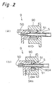
Fig. 2 shows a discharge amount adjustment mechanism of the apparatus for spraying pseudo hair increasing material ofFig. 1 ,Fig. 2(a) is a sectional view (discharge (injection): large in amount) andFig. 2(b) is a sectional view (discharge (injection): small in amount); - Reference
Fig. 5 is a sectional view showing an essential portion of still another embodiment of an apparatus for spraying pseudo hair increasing material; and - Reference
Fig. 6 is a sectional view showing an essential portion of yet another embodiment of an apparatus for spraying pseudo hair increasing material. - Specific embodiments incorporated with the present invention will be described hereinafter with reference to the drawings. Here, Reference
Figs. 1 and2 are views showing an apparatus for spraying pseudo hair increasing material according to the present embodiment (first embodiment), ReferenceFig. 1(a) is a plan view, ReferenceFig. 1(b) is a side sectional view, and ReferenceFig. 2 is a schematic view showing a state of use. In the illustration,reference numeral 1 denotes an apparatus for spraying pseudo hair increasing material (hereinafter referred to the "spraying apparatus"). - As shown in Reference
Fig. 1 , thespraying apparatus 1 according to the first embodiment includes afirst container 3 for storing therein pseudohair increasing material 2 in a form of powder or short fabrics, and asecond container 4 for storing therein propellant gas, the first andsecond containers coupler 30 coupled to thefirst container 3. - The
second container 4 is provided therein with an injection mechanism for injecting the propellant gas into thefirst container 3 through aninjection nozzle 5, thefirst container 3 being formed with adischarge port 31 for discharging the pseudohair increasing material 2 therethrough, thedischarge port 31 having an axis in alignment with that of theinjection nozzle 5, a bore of thedischarge port 31 being larger than that of aninjection port 50 formed on a distal end of theinjection nozzle 50, through operation of the injection mechanism, the propellant gas from theinjection nozzle 5 being injected to thereby cause the pseudohair increasing material 2 to be discharged from thedischarge port 31 towards a predetermined area. - The
spraying apparatus 1 according to the first embodiment will now be described in detail. - As shown in Reference
Fig. 1 , thespraying apparatus 1 according to this embodiment generally includes thefirst container 3 for storing therein the pseudohair increasing material 2 in the form of powder or short fabrics, and the cylindricalsecond container 4 for filling therein the propellant gas,
the first andsecond containers coupler 30 coupled to thefirst container 3. - The
first container 3 comprises afirst member 32 exhibiting a generally rectangular configuration in top sectional view and having an upper wall portion defined by an arcuate curved surface, and asecond member 33 formed of a box-like member having a bottom which exhibits a generally rectangular configuration in top sectional view and unremovably bonded to thefirst member 32. - An
annular coupler 30 engagingly locked to an upper part of thesecond container 4 is continuous with arear surface portion 32b of thefirst member 32. Thecoupler 30 is formed by integral molding together with thefirst container 3. In the alternative, thecoupler 30 is separately molded and then coupled to thefirst container 3 by welding or the like. - As shown in Reference
Fig. 1 , thecoupler 30 is an annular member which is formed on an upper portion thereof with anannular stopper 30a projecting inwardly and whose inside diameter is generally equal to the outside diameter of thesecond container 4. Thecoupler 30 is engagingly locked to upper part of thesecond container 4. - The
first container 3 and thesecond container 4 can easily be separated from each other by pulling up thecoupler 30 which is engagingly locked to the upper part of thesecond container 4 after ajoint tube 8 of an injection mechanism, as later described, is detached from theinjection nozzle 5. - The
first container 3 has anattachment port 34 for theinjection nozzle 5 formed in an upper center of therear surface portion 32b and adischarge port 31 for the pseudohair increasing material 2 formed in an upper center of afront surface portion 32a confronting theattachment port 34. Thedischarge port 31 is circular in section and same in inside diameter at its opposite ends. The inside diameter of thedischarge port 31 at its end on the side of the interior of thecontainer 3 is larger than the inside diameter of theinjection port 50 of theinjection nozzle 5 firmly fitted into theattachment port 34 on the side of the interior of thecontainer 3. Theattachment port 34 has a circular configuration in section and is formed in such a location that the axis of theinjection port 50 of theinjection nozzle 5 firmly fitted is in alignment with that of thedischarge port 31. - The bore of the discharge port for the pseudo hair increasing material and the bore of the injection port at a distal end of the injection nozzle in the present invention refer to the inside diameters, respectively, at the end portion on the side of the first container. In the spraying apparatus for pseudo hair increasing material of this embodiment, the bore R1 of the discharge port, the bore R2 of the injection port at the distal end of the
injection nozzle 5, the bore ratio (R1/R2) and the distance L between the discharge port and the injection port and the [preferred values] thereof are as follows. In each item listed below, the numerical value listed first shows the numerical value of each portion in this embodiment. - Discharge port bore R1 : 4 mm diameter [3 to 10 mm, particularly, 4 to 7 mm]
- Injection port bore R2 : 0.5 mm diameter; [0.2 to 1.0 mm, particularly, 0.4 to 0.8 mm]
- Bore ratio (R1/R2) : 8 [3 to 50, particularly, 5 to 15]
- Distance L between discharge port and injection port : (see
Fig. 5 ) : 44 mm [30 to 60 mm, particularly, 34 to 54 mm] - The
second container 4 is chiefly fabricated of a conventional well-known aerosol container capable of injecting the propellant gas filled therein by pushing down thenozzle member 6 disposed on an upper end portion thereof through a spring. Fitted to an upper end portion of thenozzle member 6 is a button 7 having therein a vertical conduit and a horizontal conduit communicated with each other and adapted to introduce the propellant gas into thefirst container 3. Theinjection nozzle 5, which is disposed on an upper portion within thefirst container 3 such that the propellant gas can be injected in a horizontal direction, is attached to a distal end portion of a horizontal tube portion 70 of the button 7 through a flexiblejoint tube 8. Here, thenozzle member 6, the button 7 and thejoint tube 8 constitute the injection mechanism. - The
injection nozzle 5 is a hollow tubular member made of metal. Theinjection nozzle 5 has theinjection port 50 formed on a distal end portion thereof and having the inside diameter smaller than the remaining portion. Anannular projection 51 projecting in a circumferential direction is formed on theinjection nozzle 5 at a location a little to its rear end portion from its axial center. Theinjection nozzle 5 is fixed with its area from the distal end portion where theinjection port 50 is formed to theannular projection 51 fitted to theattachment port 34 of thefirst container 3. Thejoint tube 8 made of flexible rubber is connected to theinjection nozzle 5 at its area offset to its rear end side from theannular projection 51. Through thisjoint tube 8, theinjection nozzle 5 and the injection mechanism can be separated from each other and connected together. Specifically, theinjection nozzle 5 is formed on a connecting area of thejoint tube 8 with three annular detachment-preventive projections (not shown) projecting in an outer peripheral direction, such that thejoint tube 8 will not be detached merely by increase of the internal pressure of thejoint tube 8 when in use or the like. However, thejoint tube 8 can easily be pulled out of theinjection nozzle 5 by hand. - One example of a way of use of the apparatus for spraying pseudo hair increasing material according to the first embodiment will now be described. First, the pseudo
hair increasing material 2 in the form of powder or short fabrics is stored in thefirst container 3 and the propellant gas is filled or stored in thesecond container 4. - Then, with the
aerosol container 4 held with hand, thedischarge port 31 is pointed to the area of the head where the pseudo hair-increase material is needed while confirming through a mirror or the like and actuated by operating the injection mechanism disposed at thesecond container 4. - Specifically, the button 7 is pushed downward. When the pushing pressure pushes the button 7 downward, the
nozzle member 6 is simultaneously pushed downward. As a result, the propellant gas stored or filled in thesecond container 4 is injected into thefirst container 3 via thenozzle member 6, the button 7, thejoint tube 8 and theinjection nozzle 5. - The propellant gas injected into the first container proceeds straight towards the
discharge port 31 and injected outside through thedischarge port 31 as shown inFig. 2 . The sectional area of the gas jet stream injected from theinjection nozzle 5 is somewhat increased at the area for the gas jet stream to enter the interior of thedischarge port 31 compared with at the area where the gas jet stream passes immediately after it is injected from theinjection port 50. However, since the bore of thedischarge port 31 is larger than that of theinjection port 50, the gas jet stream never circulates within thefirst container 3. By this gas jet stream, negative pressure is generated within thefirst container 3 and the gas contacting an outer peripheral portion of this velocity within thecontainer 3 is dragged and begins to move to thereby generate a swirl or vortical flow within thefirst container 3. - The pseudo
hair increasing material 2 is circulated within thefirst container 3 carried by the vortical flow. Accordingly, there is no fear that the pseudo hair increasing material is frosted unlike the case where the propellant gas is injected directly to the pseudohair increasing material 2. Moreover, the pseudo hair increasing material is never formed into a mass by being mutually tangled or press fitted under compression. - The pseudo hair increasing material coming close to this jet stream is drawn into the jet stream by the negative pressure and injected from the
discharge port 31 so as to be sprayed to a desired area of the head such as the area where hair is locally decreased. - According to the
spraying apparatus 1 of this embodiment, merely by pushing down the injection button 7, the pseudo hair increasing material in the form of powder or short fabrics can easily be sprayed to the area of the head where hair is decreased, continuously and in a stable manner. - Moreover, when the pseudo hair increasing material is circulated within the
first container 3 carried by the vortical flow, the individual pseudo hair increasing material are vigorously contacted with each other within the container and a static current generated by the contacting friction is charged to the pseudo hair increasing material. Accordingly, the sprayed pseudo hair increasing material is favorably adhered to the natural hair or the scalp of a person's head under the effect of the static current. Thus, according to thespraying apparatus 1 of this embodiment, merely by pushing down the injection button 7, the pseudo hair increasing material can be sprayed to the area of the head where hair is decreased, continuously and in a stable manner and the pseudo hair increasing material thus sprayed has a sufficient adhesive force with respect to the natural hair or the scalp of a person's head.Reference numeral 40 ofFig. 2 denotes a wrapper tube serves to keep more than a predetermined distance between thedischarge port 31 and the head, so that the sprayed pseudo hair increasing material will be normally in a good condition and in addition, to prevent the pseudo hair increasing material from dispersing outside the head, so that the pseudo hair increasing material will be more correctly sprayed to the targeted area. - Furthermore, according to the spraying apparatus of this embodiment, since the first and second containers are detachably attached to each other through the coupler, the first container can easily be replaced with a new container or a container containing the pseudo hair increasing material of a desired color in case the pseudo hair increasing material stored in the
first container 3 is used up or the selected color of the pseudo hair increasing material is not in match with the own hair of the person who needs more hair. Accordingly, even in case the pseudo-hair increasing material becomes short while the spraying operation is undergoing, the spraying operation can be immediately started again by replacing the container. It is also possible to replace the container with other containers containing the pseudo hair increasing material of different colors so that a container containing the pseudo hair increasing material of a color most suited to the person's own hair color can be selected for use. Also, when the replacement is made, the periphery and hand are not soiled by the pseudo hair increasing material. - Likewise, when the propellant gas in the
aerosol container 4 as the second container is used up, theaerosol container 4 can easily be replaced with a new aerosol container 4'. Accordingly, the propellant gas can be supplemented quite easily and the pseudo hair increasing material remained in the first container can effectively completely be used without any waste. - Reference
Figs. 3 and4 are views showing a second embodiment of a pseudo hair increasing material, ReferenceFig. 3 is a side sectional view, and ReferenceFig. 4 is a sectional view taken on line A-A' of ReferenceFig. 3 . In the illustration,reference numeral 10 denotes a spraying apparatus for pseudo hair increasing material (hereinafter referred to as the "spraying apparatus"). - As shown in Reference
Fig. 3 , the sprayingapparatus 10 according to the second embodiment generally includes, in acase 11 having a bottom, a pseudo hair increasing material storage container 3 (first container) for storing therein pseudo hair increasing material in a form of powder or short fabrics, an aerosol container 4 (second container) for storing therein a first propellant gas, an aerosol container 12 (third container) for storing therein a liquid composition for fixing pseudo hair and a second propellant gas, and an injection mechanism13 for injecting the first propellant gas into the pseudo hair increasingmaterial storage container 3 through aninjection nozzle 5 and for injecting the hair fixing liquid composition towards a predetermined area by the second propellant gas. The pseudo hair increasingmaterial storage container 3 and theinjection nozzle 5 according to this embodiment are the same in construction as the first container and theinjection nozzle 5 according to the first embodiment. The pseudo hair increasingstorage container 3 is formed with adischarge port 31 for discharging the pseudohair increasing material 2 therethrough, thedischarge port 31 having an axis in alignment with that of theinjection nozzle 5, a bore of thedischarge port 31 being larger than that of aninjection port 50 formed on a distal end of theinjection nozzle 5. The bore of thedischarge port 31, the bore of theinjection port 50 at the distal end of theinjection nozzle 5, the distance L therebetween, the range of preferred numerical values, etc. are also the same as those in the above embodiment. - In the spraying apparatus for pseudo hair increasing material according to this embodiment, through operation of the
injection mechanism 13, the hair fixing liquid composition is injected towards a predetermined area and the pseudohair increasing material 2 is discharged towards the predetermined area by the first propellant gas injected from theinjection nozzle 5, through thedischarge port 31. - The
case 11 is of a construction dividable along a B-B' plane as shown in ReferenceFig. 4 . Within thedividable case 11, the pseudohair increasing material 3, theaerosol container 4 and theaerosol container 12 are independently detachably stored. Formed within thecase 11 are fixingwall portions aerosol containers case 11. Moreover, fixingmembers 14d are disposed at predetermined locations within thecase 11. - The fixing wall portion 14c is formed with insertion holes generally coaxial with the
aerosol containers aerosol containers injection button 15 as later described. When theaerosols containers nozzle members - The
aerosol container 4 is chiefly fabricated of a conventional well-known aerosol container capable of injecting the propellant gas filled therein by pushing down thenozzle member 4a disposed on an upper end portion thereof through a spring. Theother aerosol container 12 is chiefly fabricated of a conventional well-known aerosol container capable of injecting the propellant gas and the hair fixing liquid composition filled therein by pushing down thenozzle member 12a disposed on an upper end portion thereof through a spring. - The
nozzle member 4a of theaerosol container 4 and thenozzle member 12a of theaerosol container 12 are fitted with theinjection button 15. By pushing down theinjection button 15, the two legs of theinjection button 15 simultaneously push down thenozzle members - The
injection button 15 is formed with the injection port 16 for injecting the first propellant gas stored in theaerosol container 4 and the injection port 17 for injecting the second propellant gas and the hair fixing liquid composition in theaerosol container 12, such that the propellant gas or the propellant gas and the hair fixing liquid composition are injected in opposite directions. Above the injection ports 16 and 17, aninjection conduit 15a for introducing the pseudo hair increasing material, which is discharged from thedischarge port 31 of the pseudo hair increasingstorage container 3 by the first propellant gas, outside is generally horizontally formed in theinjection button 15. - The injection port 16 is fitted with a flexible joint tube 8' made of rubber. The other end of the joint tube 8' is connected to the
injection nozzle 5 fixedly attached to the attachment port for the pseudo hair increasingmaterial storage container 3. The first propellant gas injected from the injection port 16 is injected into the pseudo hair increasingmaterial storage container 3 from theinjection port 50 at the distal end of theinjection nozzle 5 through the joint tube 8'. - The feature that an
attachment port 34 for fixedly attaching theinjection nozzle 5 is formed in an upper center of therear surface portion 32b of the pseudo hair increasingmaterial storage container 3, the construction and the manner of attachment of theinjection nozzle 5 are the same as in the first embodiment. - A
discharge port 31 for the pseudohair increasing material 2 is formed in an upper center of afront surface portion 32a confronting therear surface portion 32b where theattachment port 34 is formed, in the pseudo hair increasingmaterial storage container 3. Thedischarge port 31 is circular in section and the inside diameter of thedischarge port 31 is the same at opposite ends thereof. Thedischarge port 31 has an axis in alignment with the axis of theinjection nozzle 5 and also a bore larger than the bore of theinjection port 50 at the distal end of theinjection nozzle 5. - The
discharge port 31 is communicated with thedischarge conduit 15a of theinjection button 15 through a flexible horizontal tubular member 18 (made of rubber). The pseudo hair increasing material and the first propellant gas discharged from thedischarge port 31 are passed through thehorizontal tubular member 18 and thedischarge conduit 15a and discharged from adischarge opening portion 15b at the other end. - An opening portion 11a is formed in a front surface of the
case 11 where thedischarge opening portion 15b and the injection port 17 for injecting the second propellant gas and the hair-fixing liquid composition are open. The first propellant gas, the pseudo hair increasing material, the second propellant gas and the hair fixing liquid composition are injected towards a predetermined area from the opening portion 11a in their admixed condition. - A lever
type switch lever 20 is disposed on an upper portion of theinjection button 15 with theprojection 19 in abutment with the upper end portion of theinjection button 15. - The lever
type switch lever 20 is fixed at one end thereof by apin 21 formed on thecase 11, so that the other end portion can be moved upward and downward about the one end. The other end portion is normally biased upward under the effect of the spring for biasing thenozzle members pressing portion 22 is formed on an upper surface of the other end portion. When thepressing portion 22 is pressed downward by finger, theprojection 19 presses the upper end portion of theinjection button 15 under the principles of a lever. That is, thepin 21 and theprojection 19 function as a fulcrum and a point of application. Here, thenozzle member 4a of theaerosol container 4, thenozzle member 12a of theaerosol container 12, theinjection button 15 and the levertype switch lever 20 constitute theinjection mechanism 13. - In operation of the spraying
apparatus 10 according to this embodiment, the pseudo hair increasing material in the form of powder or short fabrics is filled or stored in the pseudo-hair increasingmaterial storage container 3 as the first container, the first propellant gas, in theaerosol container 4 as the second container, and the hair fixingliquid composition and the second propellant gas, in theaerosol container 12 as the third container, respectively and then the injection mechanism is actuated. - Specifically, with the
case 11 held with hand, the opening portion 11a disposed at the front surface of thecase 11 is pointed to the area of the head where the pseudo hair-increase material is needed while confirming through a mirror or the like and thepressing portion 22 of the levertype switch lever 20 is pushed down. When thepressing portion 22 is pushed down, theprojection 19 is lowered about thepin 21 to push down theinjection button 15. Then, by theinjection button 15, thenozzle members aerosol containers - The first propellant gas injected from the injection port 16 is injected into the pseudo hair increasing
material storage container 3 via the joint tube 8' and theinjection nozzle 5. - When the first propellant gas is injected into the pseudo hair increasing
material storage container 3, the gas proceeds straight within thecontainer 3 and is then flowed into thedischarge port 31. - The sectional area of the gas jet stream injected from the
injection nozzle 5 is somewhat increased at the area for the gas jet stream to enter the interior of thedischarge port 31 compared with at the area where the gas jet stream passes immediately after it is injected from theinjection port 50. However, since the bore of thedischarge port 31 is larger than that of theinjection port 50, the gas jet stream never circulates within the pseudo hair increasingmaterial storage container 3. By this gas jet stream, negative pressure is generated within thefirst container 3 and the gas contacting an outer peripheral portion of this velocity within thecontainer 3 is dragged and begins to move to thereby generate a swirl or vortical flow within thefirst container 3. - The pseudo hair increasing material is circulated within the
container 3 carried by the vortical flow. Accordingly, there is no fear that the pseudo hair increasing material is frosted unlike the case where the propellant gas is injected directly to the pseudo hair increasing material. Moreover, the pseudo hair increasing material is never formed into a mass by being mutually tangled or press fitted under compression. - The pseudo hair increasing material coming close to this jet stream is drawn into the jet stream by the negative pressure and introduced into the
discharge port 31. The pseudo hair increasing material thus introduced into thedischarge port 31 is passed through thehorizontal conduit 18 and thedischarge conduit 15a and then injected from thedischarge opening 15b so as to be sprayed to the area where hair is locally decreased. - When the pseudo hair increasing material is circulated within the container carried by the vortical flow, the individual pseudo hair increasing material are vigorously contacted with each other within the container and a static current generated by the contacting friction is charged to the pseudo hair increasing material. Accordingly, the sprayed pseudo hair increasing material is favorably adhered to the natural hair or the scalp of a person's head under the effect of the static current.
- The second propellant gas and the hair fixing liquid composition injected from the injection port 17 are also likewise sprayed to the area of the head where hair is locally decreased. Since the hair fixing liquid composition is sprayed simultaneous with the pseudo hair increasing material, the pseudo hair increasing material is positively adhered to the natural hair or the scalp of the head by the adhesive force attributable to the hair fixing liquid composition in addition to the adhesive force attributable to the charging of the static current.
- In this way, according to the
spraying apparatus 10 of this embodiment, merely by pushing down thepressing portion 22 of the levertype switch lever 20, the pseudo hair increasing material can be sprayed to the area of the head where hair is locally decreased, together with the hair fixing liquid composition. - In the
spraying apparatus 10 according to this embodiment, theinjection opening portion 15b and the injection port 17 for the pseudo hair increasing material are formed in such a manner as to be oriented in the same direction and formed such that the hair fixing liquid composition can be injected at a wide angle. Owing to this arrangement, the sprayed pseudo hair increasing material and hair fixing liquid composition are favorably admixed in air, so that the adhered pseudo hair increasing material will come to be more intimate with the natural hair. - Since the pseudo
hair increasing container 3, theaerosol container 4 and theaerosol container 12 are merely fixed within thecase 11 by the fixingwall portions member 14d, even when any one of the pseudo hair increasing material, the first propellant gas for the pseudo hair increasing material, the hair fixing liquid composition and the second propellant gas is used up, it can easily be supplemented by replacing the specific container removed from thecase 11. - Furthermore, in the
spraying apparatus 10 according to this embodiment, the pseudo hair increasingstorage container 3 is disposed at a backward location within thecase 11 and theaerosol containers container 3. Accordingly, the portion for storing theaerosol containers - Moreover, since the apparatus for spraying pseudo hair increasing material according to this embodiment employs, as in the first embodiment, a pseudo hair increasing material storage container obtained by adhering a plurality of members together and then integrating thereof, the pseudo hair increasing material does not leak into the
case 11 thereby keeping the interior of thecase 11 from soiling, and injection can be made continuously and in a stable manner. - The apparatus for spraying pseudo hair increasing material according to the present invention should not be limited to the above embodiments but various changes can be made without departing from the scope of the present invention. The spraying apparatus of the present invention includes, as shown in
Fig. 1 , a discharge amount adjustment mechanism for pseudo hair increasing material. -
Fig. 1 is a sectional view showing a discharge amount adjustment mechanism for pseudo hair increasing material. This dischargeamount adjustment mechanism 9 is an adjustment mechanism for adjusting the amount of the pseudo hair increasing material discharged from thedischarge port 31 or injected through thedischarge port 31, by varying the distance L between thedischarge port 31 and theinjection port 50 of theinjection nozzle 5 for the pseudo hair increasing material in the first or second embodiment. Theadjustment mechanism 9 includes anattachment port 34 disposed at the first container, anadjustment member 90 threadingly engaged with aprojection 34a forming theattachment port 34 and capable of moving back and forth in accordance with rotation, aninjection nozzle 5 capable of moving back and forth with a distal end portion thereof inserted in theattachment port 34 and a rear end portion thereof inserted in aninsertion hole 90a formed in theadjustment member 90, and acoiled spring 91 for normally biasing theinjection nozzle 5 towards theadjustment member 90 with one end portion thereof abutted with anannular projection 51 of theinjection nozzle 5. - The discharge amount is adjusted by the discharge
amount adjustment mechanism 9 in the following manner. That is, in case the discharge amount is to be increased, theadjustment member 90 is rotated in a direction for retracting theinjection nozzle 5. When theinjection nozzle 5 is retracted as shown inFig. 6(a) , the distance L between theinjection port 50 at the distal end of theinjection nozzle 5 and thedischarge port 31 is increased and the amount of the pseudo hair increasing material drawn into the jet stream formed between theinjection port 50 and theinjection port 34 is increased. As a consequence, the amount of the pseudo hair increasing material discharged from thedischarge port 34 is increased and the amount of the pseudo hair increasing material injected from theinjection opening portion 15b is also increased. - In contrast, in case the discharge amount is to be decreased, the
adjustment member 90 is rotated in the opposite direction to advance theinjection nozzle 5. When theinjection nozzle 5 is advanced as shown inFig. 2 (b) , the distance L between theinjection port 50 and thedischarge port 31 is decreased and the amount of the pseudo hair increasing material drawn into the jet stream is decreased. As a consequence, the amount of the pseudo hair increasing material discharged from thedischarge port 31 is decreased and the amount of the pseudo hair increasing material injected from theinjection opening portion 15b is also decreased. - By virtue of a provision of the discharge
amount adjustment mechanism 9 thus constructed, the amount of injection of the pseudo hair increasing material can be adjusted notwithstanding the extremely simple construction. That is, there is provided an apparatus for spraying pseudo hair increasing material, capable of performing an adjustment with a high degree of precision notwithstanding the simple construction without a need of a provision of a complicated gas supplying device, a special valve provided at the aerosol container and adapted to adjust the injection amount, etc. - In the apparatus for spraying pseudo hair increasing material according to the present invention, the
injection nozzle 5 may be formed integrally with the first container in advance. In the apparatus for spraying pseudo hair increasing material according to the embodiment shown in ReferenceFig. 5 , an injection nozzle 5' is integral with a first container 3'. Owing to this arrangement, the number of the component parts can be reduced to simplify the manufacturing management and to reduce the manufacturing cost. - In the apparatus for spraying pseudo hair increasing material according to the present invention, the first container for storing the pseudo hair increasing material is preferably, either wholly or partly, transparent or semitransparent, so that the remaining amount of the pseudo hair increasing material stored therein can easily be confirmed. Owing to this arrangement, the user feels at ease in using the apparatus while confirming the remaining amount. Moreover, the user can prepare for the case of shortage of the pseudo hair increasing material by, for example, storing a supplementing container in advance of the shortage.
- In the present invention, as the propellant gas (first propellant gas) for injecting the pseudo hair increasing material, freon gas, substitute freon, liquid petroleum gas, dimethyl ether, and the like can be used.
- Examples of the freon gas include trichloromonofluoromethane, dichlorodifluoromethane, dichlorotetrafluoroethane, trichlorotrifluoroethane and the like. Examples of the substitute freon gas include monochlorodifluoromethane, difluoroethane, trifluoroethane, tetrafluoroethane and the like. Examples of liquid petroleum gas include propane, n-butane, isobutane and the like. One or more of the propellant gas mentioned above can be used, but it is most preferable to solely use dimethylether because reduction in injection pressure during injection is small, while providing sufficient injection pressure in the temperature range of ordinary use.
- In the present invention, the above-described propellant gas for injecting the pseudo hair increasing material can also be used as the propellant gas for injecting the liquid composition for fixing pseudo hair (i.e., the second propellant gas).
- The pseudo hair increasing materials in a form of powder or short fiber used in the present invention include natural fiber such as human hair, wool, cotton and silk or regenerated fiber thereof and synthetic fiber or carbon fiber such as nylon, vinylon and polyester whose color are black or the like similar to human hair color or which can be dyed such color.
- The average diameter of the pseudo hair increasing materials in a form of powder or short fiber preferably ranges from 5 to 120 µm under optical microscope observation and the length thereof preferably ranges from 10 to 2000 µm. In order to make the length uniform to fall within the above-mentioned range, a conventional cutting method such as a guillotine cutter, or a method of pulverizing with a pulverizer followed by sieving out is applicable. Making the length uniform is not essential and distribution in length is permissible as far as the length falls within the rang of 10 to 2000 µm.
- In addition, for purpose of enhancing the scatter and separation property of the pseudo hair increasing materials, they can be treated with a conventional separation accelerator in accordance with material nature thereof.
- Examples of the separation accelerator include inorganic salts such as sodium silicate, magnesium sulfate, sodium chloride, sodium sulfate and magnesium chloride; surfactants such as anionic surfactant, cationic surfactant and amphoteric surfactant; organic silicon compounds such as colloidal silica; and alminasol and the like.
- The liquid composition for fixing pseudo hair to be injected together with the pseudo hair increasing materials is not particularly limited as far as it can be injected with the second propellant gas. Examples thereof include a composition for hair set spray, a hair growing and hair nourishing composition, a hair lotion composition, an adhesive, and the like.
- Examples of the composition for hair set spray include ones containing, as a film-forming component, one or more of mixture of cationic polymer, nonionic polymer, anionic polymer and amphoteric polymer.
- Examples of the cationic polymer include hydroxyethylcellulose hydroxypropyltrimethylammonium chloride ether (manufactured by UNION CARBIDE, under tradename "POLYMER-JR-400"), vinylpyrrolidone-N,N-dimethylaminoethylmethacrylate copolymer diethylsulfate salt (manufactured by ISP, under tradename "Gafquart 734") and the like.
- Examples of the nonionic polymer include polyvinylpyrrolidone (manufactured by BASF, under tradename "Luviskol K Series"), polyvinylpyrrolidone/vinylacetate copolymer (manufactured by BASF, under tradename "Luviskol VA Series") and the like.
- Examples of the anionic polymer include alkanolamine solution of acrylic resin (manufactured by GOO Chemical Co., under tradename: "Plascize L-53PB"), vinylacetate-crotonic acid copolymer (manufactured by HOECHST JAPAN, tradename:"ARISTFLEX A60") and the like.
- Examples of amphoteric polymer include N-methacryloylethyl N,N'-dimethylammoniumα-N-methylcarboxybetaine butylmethacrylate copolymer (manufactured by MITSUBISHI Chemical, under tradename "Yukaformer AM-75") and the like.
- Examples of the composition for hair set spray include the following formulation examples.
[Formulation Example 1 (hard type)] alkanolamine solution of acrylic resin (30 %) 5.0 wt% polyoxyethylene oleyl ether 0.02 wt% perfume 0.17 wt% ethanol 49.81 wt% LPG (propellant gas; 2.5 kg/cm2) 45.00 wt% [Formulation Example 2 (soft type)] Yukaformer AM-75 (30 %) 3.0 wt% polyoxyethylene oleyl ether 0.03 wt% perfume 0.17 wt% ethanol 51.80 wt% LPG (propellant gas; 2.5 kg/cm2) 45.00 wt% - The hair glowing and hair nourishing composition, which can be injected with the propellant gas, contains blood-flow facilitating components for peripheral blood vessel such as Vitamin E and its derivatives, Swertia herb extract, garlic extract, carrot extract, aloe extract, gentian extract, Rabdosiae herb, Angelica root extract, cepharathin, capronium chloride, and minoxidil; local stimulating components such as red pepper tincture, nonylic acid vanylamide, catharidis tincture, ginger tincture, peppermint oil, 1-menthol, camphor and nicotinate; ovarian hormon components such as estrone, estradiol and ethinylestradiol; metabolic activating components such as hinokitiol, pantothenylethylether, placenta extract, biotin and pentadecanoate glycerid; nutritive components such as Vitamines (A, B2, B6, B12, D, etc.) and amino acids (cystein, serine, methionine, leucine, tryptophane, etc.); anti-inflammatory components such as components derived from glycyrrhetinic acid and glycyrrhiza extract, hydrochloric acid diphenhydramine, lithospermum root and the like; and keratine-soluble components, antiseborrhoeic components, bactericidal components and the like.
- Specific examples of the hair glowing and hair nourishing composition include the following formulation examples.
[Formulation Example 3] dipotassium glycyrrhizinate 0.1 wt% dl-α-tocopherol acetate 0.05 wt% Swertia herb extract 1.5 wt% 1-menthol 0.1 wt% dipropylene glycol 1.0 wt% perfume appropriate amount ethanol 50.0 wt% purified water balance dimethylether (propellant gas) 15.0 wt% - Furthermore, the hair lotion composition contains hair lotion component of low viscosity such as hair liquid and can be injected in spraying by the propellant gas or the like. Examples thereof include the following formulation examples.
[Formulation Example 4] polyoxypropylenebutylether (40P.O.) 10.0 wt% ethanol 30.0 wt% perfume appropriate amount purified water balance dimethylether (propellant gas) 45.0 wt% - Examples of the adhesive include ones that contain, as the adhesive component, one or more of water-soluble substances such as polysaccharides or the derivatives thereof or polyvinyl alcohol and viscoelastic granules and that can be injected in spraying by the propellant gas or the like.
- Examples of the polysaccharides and the derivatives thereof include natural starch, caroxymethyl cellulose, dextrine, chitin, amylose and the like.
- Examples of the viscoelastic particles include natural rubber latex emulsion, emulsion of alkylacrylate vinylacetate copolymer and the like.
[Formulation Example 5] carboxymethyl cellulose 0.5 wt% polyvinyl alcohol 2.0 wt% ethanol 10.0 wt% purified water balance dimethylether (propellant gas) 30.0 wt% [Formulation Example 6] aqueous dispersion of lauric acrylate-vinyl acetate copoymer (20 %) 8.0 wt% ethanol 5.0wt% purified water balance dimethylether (propellant gas) 50.0 wt% - The apparatus for spraying pseudo hair increasing material according to the present invention is, by no means, limited to the above embodiments but various changes including dimension, configuration, etc. can be made in accordance with necessity, without departing from the scope of the present invention. For example, the
discharge port 31 may be tapered as shown in ReferenceFig. 6 . - According to the apparatus for spraying pseudo hair increasing material according to the present invention, the following effects can be exhibited.
- According to the feature of the present invention as recited in
claims - According to the feature of the invention as recited in
claims - According to the apparatus for spraying pseudo hair increasing material as recited in
claim
Claims (4)
- An apparatus for spraying pseudo hair increasing material including a first container (3) for storing therein pseudo hair increasing material (2) in a form of powder or short fabrics, and a second container (4) for storing therein propellant gas;
said first and second containers (3) and (4) being detachably coupled to each other through a coupler (30);
said second container (4) being provided therein with an injection mechanism for injecting said propellant gas into said first container (3) through an injection nozzle (5) ;
said first container (3) being formed with a discharge port (31) for discharging said pseudo hair increasing material (2) therethrough, said discharge port (31) having an axis in alignment with that of said injection nozzle (5), a bore of said discharge port (31) being larger than that of said injection port (50) formed on a distal end of said injection nozzle (5);
through operation of said injection mechanism, said propellant gas from said injection nozzle (5) being injected to thereby cause said pseudo hair increasing material (2) to be discharged from said discharge port (31) towards a predetermined area,
said apparatus for spraying pseudo hair increasing material being characterized in that it further includes a discharge amount adjustment mechanism (9) for adjusting an amount of said pseudo hair increasing material (2) to be discharged from said discharge port (31) by varying a distance (L) between said discharge port (31) for said pseudo hair increasing material (2) and said injection port (50) of said injection nozzle (5). - The apparatus for spraying pseudo hair increasing material according to claim 1, wherein said second container (4) is a cylindrical member and said coupler (30) comprises an annular member to be fixedly engaged with an upper part of said second container (4).
- An apparatus for spraying pseudo hair increasing material including a first container (3) for storing therein pseudo hair increasing material (2) in a form of powder or short fabrics, a second container (4) for storing therein a first propellant gas, a third container (12) for storing therein a liquid composition for fixing pseudo hair and a second propellant gas, and an injection mechanism for injecting said first propellant gas into said first container (3) through an injection nozzle (5) and for injecting said hair fixing liquid composition towards a predetermined area by said second propellant gas;
said first container (3) being formed with a discharge port (31) for discharging said pseudo hair increasing material (2) therethrough, said discharge port (31) having an axis in alignment with that of said injection nozzle (5), a bore of said discharge port (31) being larger than that of said injection port (50) formed on a distal end of said injection nozzle (5);
through operation of said injection mechanism, said hair fixing liquid composition being injected towards a predetermined area and said pseudo hair increasing material (2) being discharged towards said predetermined area by said first propellant gas injected from said injection nozzle (5), through said discharge port (31);
said apparatus for spraying pseudo hair increasing material being characterized in that it further includes a discharge amount adjustment mechanism (9) for adjusting an amount of said pseudo hair increasing material (2) to be discharged through said discharge port (31) by varying a distance (L) between said discharge port (31) for said pseudo hair increasing material (2) and said injection port (50) of said injection nozzle (5). - The apparatus for spraying pseudo hair increasing material (2) according to claim 3, wherein the first (3), second (4) and third containers (12) are independently detachably stored in cases, respectively.
Applications Claiming Priority (3)
| Application Number | Priority Date | Filing Date | Title |
|---|---|---|---|
| JP62951/97 | 1997-03-17 | ||
| JP06295197A JP3288949B2 (en) | 1997-03-17 | 1997-03-17 | Spraying device for artificial hair growth material |
| PCT/JP1998/001097 WO1998041332A1 (en) | 1997-03-17 | 1998-03-16 | Spraying apparatus for artificial hair augmenting agent |
Publications (3)
| Publication Number | Publication Date |
|---|---|
| EP0904843A1 EP0904843A1 (en) | 1999-03-31 |
| EP0904843A4 EP0904843A4 (en) | 2006-02-01 |
| EP0904843B1 true EP0904843B1 (en) | 2008-04-23 |
Family
ID=13215145
Family Applications (1)
| Application Number | Title | Priority Date | Filing Date |
|---|---|---|---|
| EP98907244A Expired - Lifetime EP0904843B1 (en) | 1997-03-17 | 1998-03-16 | Spraying apparatus for artificial hair augmenting agent |
Country Status (6)
| Country | Link |
|---|---|
| US (1) | US6168781B1 (en) |
| EP (1) | EP0904843B1 (en) |
| JP (1) | JP3288949B2 (en) |
| CN (1) | CN1100623C (en) |
| DE (1) | DE69839384T2 (en) |
| WO (1) | WO1998041332A1 (en) |
Families Citing this family (15)
| Publication number | Priority date | Publication date | Assignee | Title |
|---|---|---|---|---|
| EP1201317B1 (en) * | 2000-10-24 | 2008-05-14 | L'oreal | Spraying apparatus with at least two carrier gas outlets |
| FR2830778B1 (en) * | 2001-10-11 | 2004-07-09 | Oreal | DEVICE FOR SPRAYING AT LEAST ONE PRODUCT ON A SUPPORT, IN PARTICULAR A KERATINIC SUPPORT SUCH AS THE SKIN |
| FR2818101B1 (en) * | 2000-12-15 | 2003-09-26 | Oreal | DEVICE FOR SPRAYING A COSMETIC PRODUCT |
| US7140522B2 (en) * | 2003-06-26 | 2006-11-28 | Spencer Forrest, Inc. | Applicator for hair building solids |
| US8021649B2 (en) | 2007-02-22 | 2011-09-20 | Cronk Peter J | Continuous spray scalp therapy and dispensing systems for same |
| US20080206156A1 (en) * | 2007-02-22 | 2008-08-28 | Cronk Peter J | Continuous spray scalp therapy and dispensing systems for same |
| US7841494B2 (en) | 2007-03-16 | 2010-11-30 | Randall Batinkoff | Pump dispenser |
| GB2474488B (en) | 2009-10-16 | 2015-03-25 | Pangaea Lab Ltd | Hair building solids dispenser |
| GB2477913A (en) * | 2010-02-11 | 2011-08-24 | Pangaea Lab Ltd | A hair building solid agent with electrostatic effects |
| WO2015095816A1 (en) * | 2013-12-19 | 2015-06-25 | Knight Ryan | Method for eliminating baldness using hair fragments and adhesive |
| FR3039369B1 (en) * | 2015-07-31 | 2017-09-08 | Oreal | COSMETIC TREATMENT PROCESS |
| US20180027948A1 (en) * | 2016-07-29 | 2018-02-01 | Behavioral Research Group dba Hair Metrics | Method of applying hair building solids with a low rigidity, high density bristle-based applicator |
| US10166562B2 (en) | 2017-01-10 | 2019-01-01 | Top Secret Inc. | Protective cap with detachable nozzle and nozzle holder |
| JP7212212B2 (en) * | 2021-01-26 | 2023-01-25 | 東洋製罐株式会社 | Discharge device and discharge method |
| US20250197623A1 (en) | 2022-03-24 | 2025-06-19 | 3M Innovative Properties Company | Water-based adhesive composition and related methods |
Family Cites Families (15)
| Publication number | Priority date | Publication date | Assignee | Title |
|---|---|---|---|---|
| US2029408A (en) * | 1933-06-29 | 1936-02-04 | Binks Mfg Co | Powder-spraying appliance |
| US2717804A (en) * | 1946-05-06 | 1955-09-13 | Jr Roby Byron White | Spray gun |
| US3054210A (en) * | 1958-11-21 | 1962-09-18 | Union Carbide Corp | Dust and liquid spray device |
| US2993652A (en) * | 1959-07-28 | 1961-07-25 | Harold E Curry | Atomizer |
| US3263927A (en) * | 1964-05-19 | 1966-08-02 | Aero Dyne Corp | Method for spraying thixotropic glass bead mixtures and the like |
| JPS4919515B1 (en) * | 1970-03-19 | 1974-05-17 | ||
| JPS4939580B2 (en) | 1971-09-23 | 1974-10-26 | ||
| JPS61183152A (en) | 1985-02-07 | 1986-08-15 | Asahi Glass Co Ltd | Glass substrate |
| JPS61183152U (en) * | 1985-05-08 | 1986-11-15 | ||
| US4681262A (en) * | 1985-09-27 | 1987-07-21 | The Sherwin-Williams Company | Cap connecting propellant container with material container |
| JPH0626684A (en) | 1992-07-13 | 1994-02-04 | Matsushita Seiko Co Ltd | Electric part box of ventilator |
| JP3351831B2 (en) | 1992-11-02 | 2002-12-03 | 日本炭酸瓦斯株式会社 | Microfiber material ejection device |
| JP3638334B2 (en) | 1994-10-18 | 2005-04-13 | 花王株式会社 | Method and apparatus for spraying pseudo hair thickener |
| JP3563136B2 (en) | 1994-12-27 | 2004-09-08 | 株式会社ダイゾー | Powder shaker |
| JPH0929144A (en) | 1995-07-19 | 1997-02-04 | Nippon Tansan Gas Co Ltd | Microfiber material discharge device |
-
1997
- 1997-03-17 JP JP06295197A patent/JP3288949B2/en not_active Expired - Fee Related
-
1998
- 1998-03-16 DE DE69839384T patent/DE69839384T2/en not_active Expired - Lifetime
- 1998-03-16 WO PCT/JP1998/001097 patent/WO1998041332A1/en not_active Ceased
- 1998-03-16 US US09/147,265 patent/US6168781B1/en not_active Expired - Fee Related
- 1998-03-16 EP EP98907244A patent/EP0904843B1/en not_active Expired - Lifetime
- 1998-03-16 CN CN98800294A patent/CN1100623C/en not_active Expired - Fee Related
Also Published As
| Publication number | Publication date |
|---|---|
| JP3288949B2 (en) | 2002-06-04 |
| WO1998041332A1 (en) | 1998-09-24 |
| DE69839384T2 (en) | 2009-05-20 |
| CN1220621A (en) | 1999-06-23 |
| US6168781B1 (en) | 2001-01-02 |
| CN1100623C (en) | 2003-02-05 |
| DE69839384D1 (en) | 2008-06-05 |
| EP0904843A4 (en) | 2006-02-01 |
| EP0904843A1 (en) | 1999-03-31 |
| JPH10249249A (en) | 1998-09-22 |
Similar Documents
| Publication | Publication Date | Title |
|---|---|---|
| US6168781B1 (en) | Spraying apparatus for artificial hair augmenting agent | |
| CN101218036B (en) | Content discharge mechanism, and aerosol-type product and pump-type product with the same | |
| AU653143B2 (en) | Hair spray package with low volatile organic compound emission | |
| EP0745665B1 (en) | Personal cleaning composition | |
| US6415800B2 (en) | Method of shaving and a dispensing apparatus therefor | |
| JP3724812B2 (en) | Spray machine for spraying liquid products containing film-forming polymers in the form of microdroplets | |
| JP2004515317A (en) | Cosmetic spray equipment | |
| CN101203276A (en) | Product delivery system for atomizing non-liquid or highly viscous cosmetic compositions | |
| CA1248457A (en) | Process for applying reflective particles to hair | |
| EP1386669A1 (en) | Aerosol product | |
| US4915935A (en) | Process for applying reflective particles to hair | |
| JP2002326042A (en) | Spray device having at least two vector gas outlet orifices | |
| JPH10235238A (en) | Hair cosmetics | |
| JPH10236550A (en) | Aerosol spray products for hairdressing | |
| JP2004262887A (en) | Two-layer cosmetic | |
| JPH1112135A (en) | Hair cosmetics | |
| JP4628560B2 (en) | Aerosol composition and product thereof | |
| JP2020200244A (en) | Hair cosmetic | |
| JPH1149648A (en) | Hair cosmetic application products | |
| JP3638334B2 (en) | Method and apparatus for spraying pseudo hair thickener | |
| JP5183243B2 (en) | Venturi mechanism for contents injection and aerosol type products | |
| JP3351831B2 (en) | Microfiber material ejection device | |
| JP3481857B2 (en) | Simulated hair growth material discharge device | |
| JPS5628670A (en) | Foaming spray | |
| CN121042184A (en) | Shower head |
Legal Events
| Date | Code | Title | Description |
|---|---|---|---|
| PUAI | Public reference made under article 153(3) epc to a published international application that has entered the european phase |
Free format text: ORIGINAL CODE: 0009012 |
|
| AK | Designated contracting states |
Kind code of ref document: A1 Designated state(s): DE FR GB |
|
| 17P | Request for examination filed |
Effective date: 19990217 |
|
| A4 | Supplementary search report drawn up and despatched |
Effective date: 20051220 |
|
| 17Q | First examination report despatched |
Effective date: 20060622 |
|
| 17Q | First examination report despatched |
Effective date: 20060622 |
|
| GRAP | Despatch of communication of intention to grant a patent |
Free format text: ORIGINAL CODE: EPIDOSNIGR1 |
|
| GRAS | Grant fee paid |
Free format text: ORIGINAL CODE: EPIDOSNIGR3 |
|
| GRAA | (expected) grant |
Free format text: ORIGINAL CODE: 0009210 |
|
| AK | Designated contracting states |
Kind code of ref document: B1 Designated state(s): DE FR GB |
|
| REG | Reference to a national code |
Ref country code: GB Ref legal event code: FG4D |
|
| REF | Corresponds to: |
Ref document number: 69839384 Country of ref document: DE Date of ref document: 20080605 Kind code of ref document: P |
|
| EN | Fr: translation not filed | ||
| PLBE | No opposition filed within time limit |
Free format text: ORIGINAL CODE: 0009261 |
|
| STAA | Information on the status of an ep patent application or granted ep patent |
Free format text: STATUS: NO OPPOSITION FILED WITHIN TIME LIMIT |
|
| 26N | No opposition filed |
Effective date: 20090126 |
|
| PGFP | Annual fee paid to national office [announced via postgrant information from national office to epo] |
Ref country code: DE Payment date: 20110309 Year of fee payment: 14 Ref country code: GB Payment date: 20110316 Year of fee payment: 14 |
|
| PG25 | Lapsed in a contracting state [announced via postgrant information from national office to epo] |
Ref country code: FR Free format text: LAPSE BECAUSE OF FAILURE TO SUBMIT A TRANSLATION OF THE DESCRIPTION OR TO PAY THE FEE WITHIN THE PRESCRIBED TIME-LIMIT Effective date: 20090227 |
|
| GBPC | Gb: european patent ceased through non-payment of renewal fee |
Effective date: 20120316 |
|
| PG25 | Lapsed in a contracting state [announced via postgrant information from national office to epo] |
Ref country code: GB Free format text: LAPSE BECAUSE OF NON-PAYMENT OF DUE FEES Effective date: 20120316 |
|
| REG | Reference to a national code |
Ref country code: DE Ref legal event code: R119 Ref document number: 69839384 Country of ref document: DE Effective date: 20121002 |
|
| PG25 | Lapsed in a contracting state [announced via postgrant information from national office to epo] |
Ref country code: DE Free format text: LAPSE BECAUSE OF NON-PAYMENT OF DUE FEES Effective date: 20121002 |