EP0904497B1 - Zahnkupplung - Google Patents
Zahnkupplung Download PDFInfo
- Publication number
- EP0904497B1 EP0904497B1 EP97928117A EP97928117A EP0904497B1 EP 0904497 B1 EP0904497 B1 EP 0904497B1 EP 97928117 A EP97928117 A EP 97928117A EP 97928117 A EP97928117 A EP 97928117A EP 0904497 B1 EP0904497 B1 EP 0904497B1
- Authority
- EP
- European Patent Office
- Prior art keywords
- coupling
- housing
- teeth
- toothed
- component
- Prior art date
- Legal status (The legal status is an assumption and is not a legal conclusion. Google has not performed a legal analysis and makes no representation as to the accuracy of the status listed.)
- Expired - Lifetime
Links
- 230000008878 coupling Effects 0.000 title claims abstract description 177
- 238000010168 coupling process Methods 0.000 title claims abstract description 177
- 238000005859 coupling reaction Methods 0.000 title claims abstract description 177
- 230000002093 peripheral effect Effects 0.000 claims abstract description 11
- 239000000314 lubricant Substances 0.000 claims description 6
- 239000000463 material Substances 0.000 claims description 4
- 238000003466 welding Methods 0.000 claims 1
- 238000007789 sealing Methods 0.000 abstract description 12
- 230000001788 irregular Effects 0.000 abstract 1
- 235000000621 Bidens tripartita Nutrition 0.000 description 11
- 240000004082 Bidens tripartita Species 0.000 description 11
- 208000006637 fused teeth Diseases 0.000 description 11
- 239000012528 membrane Substances 0.000 description 5
- 230000007774 longterm Effects 0.000 description 3
- 230000005540 biological transmission Effects 0.000 description 2
- 238000010276 construction Methods 0.000 description 2
- 230000007797 corrosion Effects 0.000 description 2
- 238000005260 corrosion Methods 0.000 description 2
- 238000005516 engineering process Methods 0.000 description 2
- 230000001681 protective effect Effects 0.000 description 2
- 230000015572 biosynthetic process Effects 0.000 description 1
- 238000011161 development Methods 0.000 description 1
- 230000018109 developmental process Effects 0.000 description 1
- 230000000694 effects Effects 0.000 description 1
- 230000005489 elastic deformation Effects 0.000 description 1
- 239000013013 elastic material Substances 0.000 description 1
- 239000000945 filler Substances 0.000 description 1
- 210000001061 forehead Anatomy 0.000 description 1
- 238000009434 installation Methods 0.000 description 1
- 230000036316 preload Effects 0.000 description 1
- 239000012207 thread-locking agent Substances 0.000 description 1
Images


Classifications
-
- B—PERFORMING OPERATIONS; TRANSPORTING
- B61—RAILWAYS
- B61C—LOCOMOTIVES; MOTOR RAILCARS
- B61C9/00—Locomotives or motor railcars characterised by the type of transmission system used; Transmission systems specially adapted for locomotives or motor railcars
-
- F—MECHANICAL ENGINEERING; LIGHTING; HEATING; WEAPONS; BLASTING
- F16—ENGINEERING ELEMENTS AND UNITS; GENERAL MEASURES FOR PRODUCING AND MAINTAINING EFFECTIVE FUNCTIONING OF MACHINES OR INSTALLATIONS; THERMAL INSULATION IN GENERAL
- F16D—COUPLINGS FOR TRANSMITTING ROTATION; CLUTCHES; BRAKES
- F16D3/00—Yielding couplings, i.e. with means permitting movement between the connected parts during the drive
- F16D3/16—Universal joints in which flexibility is produced by means of pivots or sliding or rolling connecting parts
- F16D3/18—Universal joints in which flexibility is produced by means of pivots or sliding or rolling connecting parts the coupling parts (1) having slidably-interengaging teeth
- F16D3/185—Universal joints in which flexibility is produced by means of pivots or sliding or rolling connecting parts the coupling parts (1) having slidably-interengaging teeth radial teeth connecting concentric inner and outer coupling parts
-
- F—MECHANICAL ENGINEERING; LIGHTING; HEATING; WEAPONS; BLASTING
- F16—ENGINEERING ELEMENTS AND UNITS; GENERAL MEASURES FOR PRODUCING AND MAINTAINING EFFECTIVE FUNCTIONING OF MACHINES OR INSTALLATIONS; THERMAL INSULATION IN GENERAL
- F16D—COUPLINGS FOR TRANSMITTING ROTATION; CLUTCHES; BRAKES
- F16D3/00—Yielding couplings, i.e. with means permitting movement between the connected parts during the drive
- F16D3/84—Shrouds, e.g. casings, covers; Sealing means specially adapted therefor
- F16D3/843—Shrouds, e.g. casings, covers; Sealing means specially adapted therefor enclosed covers
- F16D3/845—Shrouds, e.g. casings, covers; Sealing means specially adapted therefor enclosed covers allowing relative movement of joint parts due to the flexing of the cover
Definitions
- the invention relates to a tooth coupling, in particular a double tooth coupling for rail vehicles, consisting essentially from a clutch housing and at least one inside of the clutch housing arranged coupling part, wherein the coupling part has a first toothing on its peripheral region has and the clutch housing on its circumferential area has a second toothing, which with the first Toothing of the coupling part forms a driving toothing, the teeth of which are movable relative to one another, and wherein each on the end faces between the clutch housing and the coupling part at least one ring-shaped, the Driving tooth protective cover is provided.
- Such tooth couplings are used in a wide variety of areas drive technology e.g. for connecting a drive shaft used with an output shaft when it has two coupling parts with rotatable shafts and if between a relative movement of the two shafts due to radial, axial and / or angular deflections occurs and from the Coupling must be balanced.
- the relative movement between the clutch housing and the clutch parts including the waves consequently lead to the relative movement between the first and second toothings of the Driving gears.
- elastic membrane sealing rings that are convex on the front are those between the clutch housing and the clutch parts radially directed end faces completely sealed locked.
- the invention is therefore based on the object of a tooth coupling to create that is designed so suitably that media exchange and uneven running when the clutch is rotating, Imbalance and wear of the sealing elements can be avoided should.
- the drive teeth and the assigned corrugated pipes can depending on the position of the peripheral areas of the clutch housing and Coupling parts to each other, i.e. outside or inside the Circumferential region of the clutch housing can be arranged, wherein in the following the gear coupling with the clutch housing inside circumferential area of the coupling parts located largely detailed is explained.
- the corrugated tube preferably consists of a bellows that is corrosion-resistant Material.
- the corrugated tube can between the clutch housing or Coupling housing connected coupling housing parts and each a coupling part biased axially or be installed in a relaxed manner and ensures axial relative movement of the clutch parts, the reset of the clutch housing to the predetermined, preferably central position between two coupling parts.
- the corrugated tube can optionally be on its front outer edge areas annular or flange-like fasteners have, which are preferably aligned parallel to each other are.
- the fasteners can be multi-ring be formed, the outer edge region of the corrugated tube bonded to one of the rings, in particular is welded.
- the corrugated pipe can have one or more walls depending on the rigidity requirements be formed, the corrugated tube in Longitudinal section preferably single or multiple meandering is trained.
- the shaft geometry can of the corrugated pipe to be installed such that the outer envelope of the corrugated tube, preferably a cylinder or a truncated cone or the like.
- the support cover consists essentially of radially directed an outer and an inner fastening part and is by means of its outer fastening part depending on the position of the driving teeth with the clutch housing or with the clutch part and by means of its inner fastening part connected to the corrugated tube, preferably clamped or welded attached and covers the associated, axially directed most of the free space on the front.
- the clutch parts each from the front to the inside of the coupling part directed with an annular, preferably circumferential trough-like recess in the cross section provided in the the corrugated tube preferably in the middle of crowning center lines of the coupling part toothings centered and to the coupling housing axis of rotation is installed axially directed.
- the support cover can with its outer attachment part on Coupling housing or on the coupling housing parts preferably attached by means of a releasable locking device be.
- the front, outer free spaces with the respectively assigned inner part of the coupling part representing inner free spaces are by at least one acting as a choke Pressure equalization opening connected through which the lubricant, in particular, flow oil and air to equalize pressure can.
- the invention opens up the possibility of any design the tooth clutches, especially the double tooth clutches the interior between the coupling parts and the clutch housing both from the outside in and vice versa Seal direction completely so that no leakage of the Lubricant from the free spaces to the outside as well as none Media can enter the drive teeth from the inside is what largely increases long-term life.
- the Invention protects the cambered gears (coupling stars) of the coupling parts on both sides on their inside and Outdoor areas long-term from wear.
- Corrugated tube which is closed all the way around the wall continues to be a simple construction of the coupling parts ensures that material costs and assembly time are saved can be. If required, corrugated pipes can also be used one behind the other, one inside the other or parallel to each other in the Recesses of the coupling parts must be placed.
- the drive teeth belonging to a clutch can preferably each from a straight internal toothing of the clutch housing and an engaging cambered External teeth of the coupling part exist.
- the invention can be used in all toothed clutches independently of the Training in the construction of the coupling parts and coupling housing and regardless of the location and education of the Drive teeth forming gears used become.
- the corrugated pipes according to the invention can, as described above, also outside the circumferential area of the clutch housing between the clutch housing and the clutch parts are attached, with front and outer Enclosure of the clutch housing by the peripheral areas of the Coupling parts the coupling part gears (first gears) as internal gears and the clutch housing gears (second toothing) designed as external toothing are.
- the clutch housing is between the internally toothed coupling parts in the form of an externally toothed Intermediate piece arranged.
- Fig. 1 is a tooth coupling according to the invention, in particular a double tooth clutch 1 with a clutch housing 2 and two coupling parts arranged inside the clutch housing 2 3,4, for example, formed in one piece are shown, the coupling parts 3, 4 inside the Coupling housing 2 each have a coupling part inner region Specify 17.65, between which a flange portion 56 is present is.
- the clutch housing 2 expediently consists of the two largely symmetrical coupling housing parts (also called bushings or sleeves) 5.6, the by means of fitting screws 23 on the clutch housing parts 5.6 existing, facing flanges 42, 43 screwed together are and a radially directed, the clutch part inner areas 17.65 sealing inner cover 45.46 contain.
- the coupling parts 3, 4 have on their outer peripheral area 7 external teeth 9,10 (first teeth) with cambered clutch teeth.
- the clutch housing 2 has 8 internal gears 11, 12 on its inner peripheral region (second toothing).
- the external teeth 9, 10 of the Coupling parts 3.4 and the internal gears 11.12 of the clutch housing 2 each form in the clutch housing parts 5,6 drive teeth 13, 14, in which accordingly a relative movement between the coupling parts 3, 4 and the internal gear teeth 11, 12 to the clutch housing 2 and the external teeth 9, 10 can also be moved relative to one another are.
- the relative movement is caused by axial and / or angular deflections of the coupling parts 3.4 to the clutch housing 2 or to the clutch housing parts 5.6.
- the axially directed end faces 19, 20 is between the Coupling housing parts 5.6 and the respectively assigned Coupling part 3, 4, a circumferential, outer free space 15 or 16 available.
- support covers 21,22 On the end faces 19, 20 of the clutch housing 2 there are support covers 21,22 provided, which is essentially in the form of a Ring disc are formed and an outer radially directed Fastening part 28, 29 and an inner fastening part Own 60.61.
- the support cover 21,22 are with their outer Fastening part 28, 29 on the clutch housing 2 or on the Coupled housing parts 5.6, the axially directed The front open spaces 15, 16 are largely covered are.
- both the associated drive teeth 13, 14 seals as well as a predetermined position of the clutch housing 2 resiliently.
- the corrugated tube 18, 47 is between the clutch housing parts 5.6 and a coupling part 3.4 axially directed installed and secures the axial relative movement of the Coupling parts 3, 4 reset the clutch housing 2 to the predetermined central position between the two coupling parts 3.4.
- the corrugated tube 18, 47 can be in the prestressed that is, tensioned or tensioned or relaxed Condition.
- the corrugated tube 18, 47 preferably consists of a bellows which is corrosion-resistant Material.
- the corrugated tube 18, 47 has on its outer edge regions on both sides annular or flange-like fasteners 53.54 or 40.41, in particular bellows flanges, which are preferred are aligned parallel to each other.
- the corrugated pipe 18.47 can on its fasteners 53.54 and 40.41 firmly attached, in particular welded.
- the corrugated tube 18, 47 can be single-walled or multi-walled be.
- FIG. 2 is an enlarged section of the corrugated tube 47 shown in the middle installation position, whereby for further Explanation also to the left-hand representation in Fig. 1 Reference is made.
- the corrugated tube 47, 18 can also be simple or in longitudinal section be formed several times in a meandering shape.
- the Shaft geometry can be changed.
- the outer envelope 55 of the corrugated tube 47, 18 of a cylindrical shape differ.
- the corrugated tubes 47, 18 are on the end face on the inner fastening parts 60.61 of the support cover 22.21 attached.
- the coupling parts 4, 3 are each from the end face 20, 19 directed towards the coupling part interior area 65, 17 with a annular or circumferential, cross-sectional trough-shaped recess 50 and 51 provided in which Corrugated tube 47 or 18 preferably centered on the crowning center lines 52 or 48 of the coupling part teeth 10.9 centered and axially biased to the respective support cover 22,21 is installed.
- the corrugated tubes 18, 47 can for example through a screw connection, a weld or a Deadlock or the like be attached, the weld at least one outer edge side of the corrugated tube 47, 18 preferably without existing own fastening element on the Support cover 22,21 is feasible.
- the outer free spaces 16, 15 can expediently be connected to the in each case associated inner part of the coupling part representing inner free spaces 65.17 by at least one as a choke acting pressure equalization opening 30 (FIG. 2), 31 (FIG. 3) be connected through which the lubricant, especially oil and air can flow to equalize pressure.
- the pressure compensation openings 30, 31 are each in the connection area a protruding external toothed ring 49.44 preferably directed paraxially between the outer Free space 16.15 and the coupling part inner area 65.17 arranged.
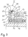
- Fig. 3 is a part of the section of FIG. 1 in one shown enlarged view. The explanation is Fig. 1 to be considered.
- the support covers 21, 22 are on the clutch housing parts 5, 6 attached via a releasable locking device 39, 38, which essentially consists of an outer radial annular groove 34.35 in the clutch housing parts 5.6, from a radial inner annular groove 32,33 in the support covers 21,22 and one resilient ring, in particular snap ring 24.25, when locked in both opposing ring grooves 32,34 or 33.35 intervenes.
- the locking springy Rings 24, 25 are form-fitting to the ring grooves 32, 33, 34, 35 educated.
- each at least three openings especially threaded holes 26 and 27 provided, which are offset by about 120 ° to the outer fastening parts 29, 28 preferably radially from the outside are introduced.
- the support cover 21,22 can also with their outer fastening parts 28.29 by simple screw connections on the front be attached to the clutch housing parts 5.6.
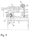
- FIG. 4 is a section similar to FIG. 2, 3 Attachment of the corrugated tube 47 on the support cover 66 and on the Coupling part 4 shown in a simplified manner of assembly.
- the corrugated tube 47 on the one hand on the end face at an outer edge region without integral fastening element on the associated support cover 66 at the connection point 67 directly attached, in particular welded or get stuck.
- the corrugated tube 47 can be on the inside of the other Outer edge area and the coupling part 4 facing an annular Have fastener 68, which also has several rings, e.g. from a welded to the corrugated tube 47, outer clamping ring 69 and a fitted in this, guided inner fitting ring 70, be formed can, the attachment to the coupling part 4 by means of the threaded bore located in the fitting ring 70 and associated Thread lock 71 takes place, so that by the screw the clamping ring 69 between the fitting ring 70 and the coupling part 4 is jammed.
- annular Have fastener 68 which also has several rings, e.g. from a welded to the corrugated tube 47, outer clamping ring 69 and a fitted in this, guided inner fitting ring 70, be formed can, the attachment to the coupling part 4 by means of the threaded bore located in the fitting ring 70 and associated Thread lock 71 takes place, so that by the screw the clamping ring 69 between the fitting ring 70 and
- Corrugated tube 47 on the inner fastening part 60 of the associated Support cover 66 can also have its outer fastening part 28 simplified form, in particular flanged and e.g. by a screw connection 72 on the outside flange Coupling part housing 6 may be attached.
- outer fastening part 28 simplified form, in particular flanged and e.g. by a screw connection 72 on the outside flange Coupling part housing 6 may be attached.
- double tooth clutches the arrangement of the other corrugated tube 18 is the same Way provided.
- FIG. 5 shows the tooth coupling 1 according to the invention shown in FIG. 1 Functionally shown in a radial deflection.
- the invention can also be used for tooth clutches, in particular Double tooth clutches in which the driving tooth area from cambered second toothings (External teeth) of the clutch housing or the clutch housing parts and straight first gears (Internal teeth) of the coupling parts.
Landscapes
- Engineering & Computer Science (AREA)
- General Engineering & Computer Science (AREA)
- Mechanical Engineering (AREA)
- Transportation (AREA)
- Mechanical Operated Clutches (AREA)
- Joints Allowing Movement (AREA)
- Gears, Cams (AREA)
- Diaphragms And Bellows (AREA)
- Sealing Devices (AREA)
- Joints With Sleeves (AREA)
Description
- Fig. 1
- eine schematische Darstellung mit einem halben Längsschnitt einer erfindungsgemäßen Doppelzahnkupplung,
- Fig. 2
- einen vergrößerten Ausschnitt längs der Kreislinie I aus dem Wellrohrumfeld in Fig.1,
- Fig. 3
- einen vergrößerten Ausschnitt längs der Kreislinie II aus dem Befestigungsumfeld des Stützdeckels in Fig.1,
- Fig. 4
- einen vergrößerten Ausschnitt ähnlich den Fig. 2,3 mit einem mehrringteiligen Befestigungselement am Wellrohr und
- Fig. 5
- eine schematische Darstellung der Doppelzahnkupplung nach Fig. 1 bei radialer Auslenkung der Kupplungsteile.
- 1
- Doppelzahnkupplung
- 2
- Kupplungsgehäuse
- 3
- Kupplungsteil
- 4
- Kupplungsteil
- 5
- Kupplungsgehäuseteil
- 6
- Kupplungsgehäuseteil
- 7
- Umfangsbereich
- 8
- Umfangsbereich
- 9
- Außenverzahnung
- 10
- Außenverzahnung
- 11
- Innenverzahnung
- 12
- Innenverzahnung
- 13
- Mitnahmeverzahnung
- 14
- Mitnahmeverzahnung
- 15
- Freiraum
- 16
- Freiraum
- 17
- Kupplungsteilinnenbereich
- 18
- Wellrohr
- 19
- Stirnseite
- 20
- Stirnseite
- 21
- Stützdeckel
- 22
- Stützdeckel
- 23
- Paßschrauben
- 24
- Ring
- 25
- Ring
- 26
- Öffnung
- 27
- Öffnung
- 28
- äußeres Befestigungsteil
- 29
- äußeres Befestigungsteil
- 30
- Druckausgleichsöffnung
- 31
- Druckausgleichsöffnung
- 32
- innere Ringnut
- 33
- innere Ringnut
- 34
- äußere Ringnut
- 35
- äußere Ringnut
- 36
- Bombierungsmittellinienpunkt
- 37
- Bombierungsmittellinienpunkt
- 38
- Verriegelungseinrichtung
- 39
- Verriegelungseinrichtung
- 40
- Befestigungselement
- 41
- Befestigungselement
- 42
- Flansch
- 43
- Flansch
- 44
- Außenverzahnungsring
- 45
- Innendeckel
- 46
- Innendeckel
- 47
- Wellrohr
- 48
- Bombierungsmittellinie
- 49
- Außenverzahnungsring
- 50
- Aussparung
- 51
- Aussparung
- 52
- Bombierungsmittellinie
- 53
- Befestigungselement
- 54
- Befestigungselement
- 55
- Einhüllende
- 56
- Flanschbereich
- 57
- Einfüllöffnung
- 58
- Einfüllöffnung
- 59
- Kupplungsgehäusedrehachse
- 60
- inneres Befestigungsteil
- 61
- inneres Befestigungsteil
- 62
- Verschlußteil
- 63
- Kupplungsteildrehachse
- 64
- Kupplungsteildrehachse
- 65
- Kupplungsteilinnenbereich
- 66
- Stützdeckel
- 67
- Verbindungsstelle
- 68
- Befestigungselement
- 69
- Verklemmungsring
- 70
- Paßring
- 71
- Schraubensicherung
- 72
- Verschraubung
- δ
- Auslenkwinkel
Claims (21)
- Zahnkupplung, insbesondere Doppelzahnkupplung (1) für Schienenfahrzeuge, bestehend im wesentlichen aus einem Kupplungsgehäuse (2;5,6) und mindestens einem innerhalb des Kupplungsgehäuses (2;5,6) angeordneten Kupplungsteil (3,4), wobei das Kupplungsteil (3,4) an seinem Umfangsbereich (7) eine erste Verzahnung (9,10) besitzt und das Kupplungsgehäuse (2;5,6) an seinem Umfangsbereich (8) eine zweite Verzahnung (11,12) aufweist, die mit der ersten Verzahnung (9,10) des Kupplungsteils (3,4) eine Mitnahmeverzahnung (13,14) bildet, deren Verzahnungen (9,11;10,12) relativ zueinander bewegbar sind, und wobei jeweils an Stirnseiten (19,20) zwischen dem Kupplungsgehäuse (2;5,6) und dem Kupplungsteil (3,4) mindestens ein ringscheibenförmiger, die Mitnahmeverzahnungen (13,14) schützender Stützdeckel (21,22) vorgesehen ist,
dadurch gekennzeichnet,
daß zwischen dem Kupplungsgehäuse (2;5,6) und jeweils einem Kupplungsteil (3,4) mindestens ein an zumindest einem von beiden Teilen (2,3;2,4 bzw. 5,3;6,4) befestigtes, axial gerichtetes Wellrohr (18,47) angeordnet ist, das sowohl die Mitnahmeverzahnung (13,14) abdichtet als auch eine vorgegebene Lage des Kupplungsgehäuses (2;5,6) federnd einstellt. - Zahnkupplung nach Anspruch 1,
dadurch gekennzeichnet,
daß die Wellrohre (18,47) zwischen dem Kupplungsgehäuse (2) bzw. den zum Kupplungsgehäuse (2) verbundenen Kupplungsgehäuseteilen (5,6) und jeweils einem Kupplungsteil (3,4) axial gerichtet vorgespannt oder entspannt eingebaut sind und bei axialer Relativbewegung der Kupplungsteile (3,4) die Rückstellung des Kupplungsgehäuses (2;5,6) auf eine vorgegebene, vorzugsweise mittige Lage zwischen beiden Kupplungsteilen (3,4) sichern. - Zahnkupplung nach Anspruch 1 oder 2,
dadurch gekennzeichnet,
daß das Wellrohr (18,47) vorzugsweise aus einem Balg korrosionsfesten Werkstoffs besteht. - Zahnkupplung nach Anspruch 3,
dadurch gekennzeichnet,
daß das Wellrohr (18,47) mindestens einwandig ausgebildet ist. - Zahnkupplung nach Anspruch 4,
dadurch gekennzeichnet,
daß das Wellrohr (18,47) im Längsschnitt mindestens einfach mäanderförmig ausgebildet ist. - Zahnkupplung nach Anspruch 3 bis 5,
dadurch gekennzeichnet,
daß je nach vorgesehener Beanspruchung die Wellengeometrie des Wellrohres (18,47) derart ausgebildet ist, daß die äußere Einhüllende (55) des Wellrohres (18,47) eine geometrische Figur, vorzugsweise einen Zylinder oder einen Kegelstumpf darstellt. - Zahnkupplung nach Anspruch 1 bis 6,
dadurch gekennzeichnet,
daß das Wellrohr (18,47) an mindestens einem seiner stirnseitigen Außenrandbereichen ein ringförmiges oder flanschartiges Befestigungselement (53,54;40,41;68) aufweist. - Zahnkupplung nach Anspruch 7,
dadurch gekennzeichnet,
daß die Befestigungselemente (53,54;40,41;68) der Wellrohre (18,47) mehrringteilig sind und im wesentlichen jeweils einen äußeren Verklemmungsring (69) und einen darin einfügbaren Paßring (70) enthalten, wobei die Wellrohre (18,47) an den Verklemmungsringen (69) befestigt, insbesondere mit den Ringen (69) stoffschlüssig verbunden sind und die Verklemmungsringe (69) mittels der verschraubbaren Paßringe (70) an den Kupplungsteilen (3,4) bzw. am Kupplungsgehäuse (2) gehaltert sind. - Zahnkupplung nach Anspruch 2,
dadurch gekennzeichnet,
daß das Wellrohr (18,47) sich in einer ringförmigen Aussparung (50,51) zwischen dem Kupplungsgehäuse (2;5,6) und dem Kupplungsteil (3,4) befindet. - Zahnkupplung nach Anspruch 9,
dadurch gekennzeichnet,
daß in der Aussparung (50;51) Wellrohre hintereinander, ineinander und/oder parallel zueinander plaziert sind. - Zahnkupplung nach Anspruch 9 oder 10,
dadurch gekennzeichnet,
daß die Kupplungsteile (3,4) jeweils von der Stirnseite (19,20) aus zu ihrem Kupplungsteilinnenbereich (17,65) gerichtet mit einer ringförmigen, vorzugsweise umlaufenden querschnittsmäßig muldenartigen Aussparung (50;51) versehen sind, in der das Wellrohr (18;47) vorzugsweise mittig zu einer Bombierungsmittellinie (48;52) der Kupplungsteilverzahnung (9,10) zentriert und zur Kupplungsgehäusedrehachse (59) axial gerichtet eingebaut ist. - Zahnkupplung nach Anspruch 1 bis 11,
dadurch gekennzeichnet,
daß das Kupplungsgehäuse (2) im wesentlichen aus zwei vorzugsweise symmetrisch ausgebildeten Kupplungsgehäuseteilen (5,6) besteht, die miteinander verbunden, insbesondere mittels Paßschrauben (23) an vorhandenen, an den Kupplungsgehäuseteilen (5,6) angeformten, einander zugewandten Flanschen (42,43) zusammengeschraubt sind und vorzugsweise im Flanschbereich (56) zum jeweiligen Kupplungsteilinnenbereich (17,65) gerichtet einen am jeweiligen Kupplungsgehäuseteil (5,6) befestigten, innenabdichtenden Innendeckel (45,46) enthalten. - Zahnkupplung nach Anspruch 12,
dadurch gekennzeichnet,
daß die Mitnahmeverzahnungen (13,14) vorzugsweise jeweils aus einer geraden Innenverzahnung (11,12) des Kupplungsgehäuses (2;5,6) und einer eingreifenden bombierten Außenverzahnung (9,10) des Kupplungsteils (3,4) bestehen. - Zahnkupplung nach mindestens einem der Ansprüche 1 bis 11 oder 1 bis 12,
dadurch gekennzeichnet,
daß das Kupplungsgehäuse (2;5,6) zwischenstückartig ausgebildet ist und das Wellrohr (18,47) sich außerhalb des Umfangsbereiches des zwischenstückartig ausgebildeten Kupplungsgehäuses (2;5,6) befindet sowie bei stirnseitiger und äußerer Umfassung des Kupplungsgehäuses (2) durch die Umfangsbereiche der Kupplungsteile (3,4) die Kupplungsteilverzahnungen in Form der ersten Verzahnungen als Innenverzahnungen und die Kupplungsgehäuseverzahnungen in Form der zweiten Verzahnungen als Außenverzahnungen ausgebildet sind. - Zahnkupplung nach Anspruch 14,
dadurch gekennzeichnet,
daß die Wellrohre (18,47) Mitnahmeverzahnungen abdichten, die vorzugsweise aus bombierten zweiten Verzahnungen in Form von Außenverzahnungen des Kupplungsgehäuses bzw. der Kupplungsgehäuseteile und aus geraden ersten Verzahnungen in Form von Innenverzahnungen der Kupplungsteile bestehen. - Zahnkupplung nach den Ansprüchen 1 bis 15,
dadurch gekennzeichnet,
daß im Kupplungsgehäuse (2) bzw. in den Kupplungsgehäuseteilen (5,6) mindestens eine verschließbare, insbesondere verschraubbare Einfüllöffnung (57,58) zur Einfüllung des Schmiermittels in die durch Innendeckel (45,46) zum Flanschbereich (56) abgegrenzten Kupplungsteilinnenbereiche (17,65) vorhanden ist. - Zahnkupplung nach mindestens einem der Ansprüche 1 bis 16, dadurch gekennzeichnet,
daß der Stützdeckel (21,22) mittels seines äußeren Befestigungsteils (28,29) am Kupplungsgehäuse (2;5,6) bzw. am Kupplungsteil (3,4) und mittels seines inneren Befestigungsteils (60,61) am Wellrohr (18,47) befestigt, vorzugsweise verschweißt oder verklemmt ist. - Zahnkupplung nach Anspruch 17,
dadurch gekennzeichnet,
daß die Stützdeckel (21,22) mittels ihrer äußeren Befestigungsteile (28,29) am Kupplungsgehäuse (2;5,6) bzw. an den Kupplungsteilen (3,4) vorzugsweise jeweils durch eine lösbare Verriegelungseinrichtung (38,39) befestigt sind. - Zahnkupplung nach mindestens einem der Ansprüche 1 bis 18, dadurch gekennzeichnet,
daß sich zwischen Stützdeckel (21,22) und Mitnahmeverzahnungen (13,14) wellrohrabgedichtete Freiräume (15,16) befinden, die mit jeweils zugeordneten, innere Freiräume darstellenden Kupplungsteilinnenbereichen (17,65) durch mindestens eine als Drossel wirkende Druckausgleichsöffnung (30,31) verbunden sind, durch die das Schmiermittel, insbesondere Öl sowie Luft druckausgleichend strömen kann. - Zahnkupplung nach Anspruch 19,
dadurch gekennzeichnet,
daß die einander zugeordneten Freiräume (15,17) bzw. (16,65) als Luftfeder ausgebildet sind. - Zahnkupplung nach Anspruch 20,
dadurch gekennzeichnet,
daß mit dem gewählten Querschnitt der Druckausgleichsöffnungen (30,31) die Luftfederkräfte festgelegt sind.
Applications Claiming Priority (3)
| Application Number | Priority Date | Filing Date | Title |
|---|---|---|---|
| DE29610299U DE29610299U1 (de) | 1996-06-12 | 1996-06-12 | Zahnkupplung |
| DE29610299U | 1996-06-12 | ||
| PCT/DE1997/001175 WO1997047894A1 (de) | 1996-06-12 | 1997-06-11 | Zahnkupplung |
Publications (2)
| Publication Number | Publication Date |
|---|---|
| EP0904497A1 EP0904497A1 (de) | 1999-03-31 |
| EP0904497B1 true EP0904497B1 (de) | 1999-10-27 |
Family
ID=8025085
Family Applications (1)
| Application Number | Title | Priority Date | Filing Date |
|---|---|---|---|
| EP97928117A Expired - Lifetime EP0904497B1 (de) | 1996-06-12 | 1997-06-11 | Zahnkupplung |
Country Status (8)
| Country | Link |
|---|---|
| US (1) | US6283869B1 (de) |
| EP (1) | EP0904497B1 (de) |
| JP (1) | JP3236625B2 (de) |
| CN (1) | CN1101899C (de) |
| AT (1) | ATE186104T1 (de) |
| DE (2) | DE29610299U1 (de) |
| ES (1) | ES2140980T3 (de) |
| WO (1) | WO1997047894A1 (de) |
Families Citing this family (24)
| Publication number | Priority date | Publication date | Assignee | Title |
|---|---|---|---|---|
| DE29610299U1 (de) * | 1996-06-12 | 1996-09-19 | KWD Kupplungswerk Dresden GmbH, 01159 Dresden | Zahnkupplung |
| DE29808627U1 (de) | 1998-05-13 | 1998-07-23 | Power Transmission Company, N.V., Oostkamp | Bogenzahnkupplung |
| DE10136903A1 (de) * | 2001-07-28 | 2003-02-06 | Veit Schmidt | Wellrohr-Kupplungsvorrichtung |
| US6524191B1 (en) * | 2001-09-21 | 2003-02-25 | James O. Tennies | Inverted coupling assembly |
| DE102005008920A1 (de) * | 2005-02-24 | 2006-09-14 | Wittenstein Ag | Kupplung zum Verbinden zweier Bauteile |
| DE202005015769U1 (de) * | 2005-09-30 | 2006-01-19 | Kwd Kupplungswerk Dresden Gmbh | Kardanische Doppelgelenkkupplung für Schienenfahrzeuge |
| JP5101459B2 (ja) * | 2008-10-29 | 2012-12-19 | 三菱重工業株式会社 | ギアカップリングの潤滑剤シール構造 |
| US8783995B2 (en) * | 2011-02-25 | 2014-07-22 | Deere & Company | Coupler for promoting lubrication of shaft splines |
| US8820753B2 (en) | 2011-04-26 | 2014-09-02 | Mitsubishi Heavy Industries, Ltd. | Lubricant sealing structure for gear coupling |
| WO2013035172A1 (ja) * | 2011-09-07 | 2013-03-14 | 三菱電機株式会社 | ギアカップリング |
| CN102537104B (zh) * | 2012-02-11 | 2014-06-11 | 郑州机械研究所 | 齿式联轴器 |
| DE202013010596U1 (de) * | 2013-11-27 | 2014-01-20 | Kwd Kupplungswerk Dresden Gmbh | Kupplung mit balggeschützter formschlüssiger Mitnahmeverbindung |
| DE202014007550U1 (de) | 2014-09-12 | 2014-10-23 | Kwd Kupplungswerk Dresden Gmbh | Zahnkupplung |
| CN104235209B (zh) * | 2014-09-15 | 2017-05-17 | 镇江索达联轴器有限公司 | 非标鼓形齿联轴器 |
| US9551413B2 (en) | 2014-09-25 | 2017-01-24 | Renold Plc | Lubricated gear coupling |
| DE102015007711A1 (de) | 2015-06-17 | 2016-12-22 | HENKE Property UG (haftungsbeschränkt) | Doppelzahnkupplung zur Verbindung einer angetriebenen Welle mit einer getriebenen Welle |
| US9951810B2 (en) | 2016-01-20 | 2018-04-24 | Summit Esp, Llc | Electrical submersible motor radial support bearing |
| US9976602B2 (en) * | 2016-02-23 | 2018-05-22 | Summit Esp, Llc | Torque transmitting coupling for an electrical submersible pump equipment string |
| GB2548622A (en) * | 2016-03-24 | 2017-09-27 | Goodrich Actuation Systems Ltd | Splined couplings |
| CN106321672A (zh) * | 2016-11-10 | 2017-01-11 | 山东崇盛冶金氧枪有限公司 | 齿式联轴器 |
| EP3536998B1 (de) * | 2018-03-05 | 2022-08-03 | Hamilton Sundstrand Corporation | Selbstzentrierende flexible kupplung |
| CN108679108A (zh) * | 2018-07-27 | 2018-10-19 | 泰尔重工股份有限公司 | 一种高转速鼓形齿联轴器及其润滑方法 |
| FR3092062B1 (fr) | 2019-01-30 | 2026-02-06 | Speedinnov | Bogie de véhicule ferrovaire et véhicule ferroviaire associé |
| RU193204U1 (ru) * | 2019-07-03 | 2019-10-16 | Общество с ограниченной ответственностью "СЕВЗАПСПЕЦМАШ" | Зубчатая муфта |
Family Cites Families (21)
| Publication number | Priority date | Publication date | Assignee | Title |
|---|---|---|---|---|
| US1770743A (en) * | 1926-05-10 | 1930-07-15 | Poole Engineering And Machine | Flexible shaft coupling |
| US1843211A (en) * | 1930-06-23 | 1932-02-02 | Penn Machine Company | Flexible shaft coupling |
| US2104669A (en) | 1935-10-17 | 1938-01-04 | Carl D Peterson | Flexible clutch shaft construction for automotive power plants |
| US2403389A (en) * | 1944-04-21 | 1946-07-02 | Gen Electric | Flexible gear coupling arrangement |
| US2510414A (en) * | 1949-01-05 | 1950-06-06 | Sier Bath Gear And Pump Co Inc | Flexible coupling for shafts |
| US3815887A (en) * | 1972-03-21 | 1974-06-11 | Hercules Inc | Plastic spring |
| CH634133A5 (de) * | 1979-02-16 | 1983-01-14 | Maag Zahnraeder & Maschinen Ag | Doppelgelenkkupplung. |
| DE3407275A1 (de) * | 1984-02-28 | 1985-08-29 | Kraftwerk Union AG, 4330 Mülheim | Einrichtung an einer rotierenden maschine zur waermebeweglichen und abdichtenden kopplung zweier konzentrischer wellen |
| US4650441A (en) * | 1986-03-28 | 1987-03-17 | Bethlehem Steel Corporation | Flexible gear coupling inspection port |
| US4877224A (en) * | 1988-08-31 | 1989-10-31 | Watts James L | Corrugated energy absorber |
| US4895352A (en) * | 1989-01-09 | 1990-01-23 | Simmons Company | Mattress or cushion spring array |
| RU1803627C (ru) * | 1990-09-25 | 1993-03-23 | Днепропетровский Металлургический Институт | Зубчато-роликова муфта |
| DE9309829U1 (de) * | 1993-07-01 | 1994-08-04 | Hurth Getriebe und Zahnräder GmbH, 80809 München | Zahnkupplung, insbesondere für ein Antriebsaggregat eines Schienenfahrzeugs |
| DE4321986C2 (de) * | 1993-07-01 | 1999-02-18 | Zf Hurth Bahntechnik Gmbh | Zahnkupplung, insbes. für ein Antriebsaggregat eines Schienenfahrzeugs |
| US5370427A (en) * | 1994-01-10 | 1994-12-06 | General Electric Company | Expansion joint for fluid piping with rotation prevention member |
| BE1008101A3 (fr) * | 1994-04-05 | 1996-01-16 | Paul Egide Boucquey | Accouplement de transmission d'un couple de rotation. |
| DE4441718A1 (de) * | 1994-11-23 | 1996-05-30 | Stoeller Dichtungstechnik Ges | Faltenbalg |
| DE29506461U1 (de) * | 1995-04-15 | 1995-06-22 | Renk Tacke Gmbh, 86159 Augsburg | Doppelgelenkkupplung |
| DE29508896U1 (de) * | 1995-05-30 | 1996-10-02 | WATTEEUW SPECIAL PRODUCTS N.V., Oostkamp | Zahnkupplung |
| DE29610299U1 (de) * | 1996-06-12 | 1996-09-19 | KWD Kupplungswerk Dresden GmbH, 01159 Dresden | Zahnkupplung |
| JP3302891B2 (ja) * | 1996-10-31 | 2002-07-15 | 三菱電機株式会社 | 可とう歯車継手 |
-
1996
- 1996-06-12 DE DE29610299U patent/DE29610299U1/de not_active Expired - Lifetime
- 1996-10-29 DE DE19644884A patent/DE19644884C1/de not_active Expired - Lifetime
-
1997
- 1997-06-11 CN CN97195363A patent/CN1101899C/zh not_active Expired - Lifetime
- 1997-06-11 WO PCT/DE1997/001175 patent/WO1997047894A1/de not_active Ceased
- 1997-06-11 US US09/202,739 patent/US6283869B1/en not_active Expired - Lifetime
- 1997-06-11 ES ES97928117T patent/ES2140980T3/es not_active Expired - Lifetime
- 1997-06-11 JP JP50106698A patent/JP3236625B2/ja not_active Expired - Lifetime
- 1997-06-11 EP EP97928117A patent/EP0904497B1/de not_active Expired - Lifetime
- 1997-06-11 AT AT97928117T patent/ATE186104T1/de active
Also Published As
| Publication number | Publication date |
|---|---|
| US6283869B1 (en) | 2001-09-04 |
| EP0904497A1 (de) | 1999-03-31 |
| WO1997047894A1 (de) | 1997-12-18 |
| JP3236625B2 (ja) | 2001-12-10 |
| DE29610299U1 (de) | 1996-09-19 |
| DE19644884C1 (de) | 1997-12-11 |
| CN1101899C (zh) | 2003-02-19 |
| JP2000503750A (ja) | 2000-03-28 |
| ATE186104T1 (de) | 1999-11-15 |
| ES2140980T3 (es) | 2000-03-01 |
| CN1221478A (zh) | 1999-06-30 |
Similar Documents
| Publication | Publication Date | Title |
|---|---|---|
| EP0904497B1 (de) | Zahnkupplung | |
| DE4115217C2 (de) | Lagerungseinheit | |
| DE3624496A1 (de) | Torsionsschwingungsdaempfer mit dichtem aufbau | |
| EP0611895A2 (de) | Doppelmembrankupplung | |
| WO2009115316A1 (de) | Stützanordnung zur axial und radial nachgiebigen abstützung eines wellenlagers | |
| DE10349968A1 (de) | Radiale Drehdurchführung | |
| EP0131881A2 (de) | Drehelastische, schwingungsdämpfende Wellenkupplung | |
| DE2917243C2 (de) | Radnabenverbindung | |
| DE4017226A1 (de) | Verzweigungsgetriebe | |
| EP0121779B1 (de) | Ausgleichskupplung | |
| EP0035283A1 (de) | Wellenkupplung | |
| DE2318629B2 (de) | Zentriervorrichtung für eine drehelastische Wellenkupplung | |
| DE3938261A1 (de) | Hochelastische wellenkupplung | |
| DE19531190C1 (de) | Schwingungsdämpfendes torsionselastisches Wellengelenk, insbesondere für den Antriebsstrang von Kraftfahrzeugen | |
| DE102005013721B4 (de) | Flexible Ganzstahl-Lamellenkupplung | |
| DE4332465A1 (de) | Zweimassenschwungrad | |
| DE102015007688B4 (de) | Zahnkupplung | |
| EP0359917A1 (de) | Drehwinkelverstellbare Ganzstahlkupplung | |
| DE2853839A1 (de) | Doppelachsantrieb fuer drehgestelle von schienenfahrzeugen | |
| DE102007050360A1 (de) | Elastische Wellenkupplung | |
| DE202008002709U1 (de) | Lageranordnung | |
| DE4001145C2 (de) | ||
| DE19907414B4 (de) | Vorrichtung zum Dämpfen von Schwingungen, insbesondere Torsionsschwingungsdämpfer | |
| DE2937237C2 (de) | Dichtungsanordnung | |
| DE3442738A1 (de) | Elastische wellenkupplung mit drehschwingungsdaempfung |
Legal Events
| Date | Code | Title | Description |
|---|---|---|---|
| PUAI | Public reference made under article 153(3) epc to a published international application that has entered the european phase |
Free format text: ORIGINAL CODE: 0009012 |
|
| 17P | Request for examination filed |
Effective date: 19981016 |
|
| AK | Designated contracting states |
Kind code of ref document: A1 Designated state(s): AT BE ES FI FR GB NL |
|
| GRAG | Despatch of communication of intention to grant |
Free format text: ORIGINAL CODE: EPIDOS AGRA |
|
| GRAG | Despatch of communication of intention to grant |
Free format text: ORIGINAL CODE: EPIDOS AGRA |
|
| GRAH | Despatch of communication of intention to grant a patent |
Free format text: ORIGINAL CODE: EPIDOS IGRA |
|
| 17Q | First examination report despatched |
Effective date: 19990412 |
|
| GRAH | Despatch of communication of intention to grant a patent |
Free format text: ORIGINAL CODE: EPIDOS IGRA |
|
| GRAA | (expected) grant |
Free format text: ORIGINAL CODE: 0009210 |
|
| AK | Designated contracting states |
Kind code of ref document: B1 Designated state(s): AT BE ES FI FR GB NL |
|
| REF | Corresponds to: |
Ref document number: 186104 Country of ref document: AT Date of ref document: 19991115 Kind code of ref document: T |
|
| GBT | Gb: translation of ep patent filed (gb section 77(6)(a)/1977) |
Effective date: 20000127 |
|
| ET | Fr: translation filed | ||
| REG | Reference to a national code |
Ref country code: ES Ref legal event code: FG2A Ref document number: 2140980 Country of ref document: ES Kind code of ref document: T3 |
|
| PLBE | No opposition filed within time limit |
Free format text: ORIGINAL CODE: 0009261 |
|
| STAA | Information on the status of an ep patent application or granted ep patent |
Free format text: STATUS: NO OPPOSITION FILED WITHIN TIME LIMIT |
|
| 26N | No opposition filed | ||
| PGFP | Annual fee paid to national office [announced via postgrant information from national office to epo] |
Ref country code: FI Payment date: 20010608 Year of fee payment: 5 |
|
| REG | Reference to a national code |
Ref country code: GB Ref legal event code: IF02 |
|
| PG25 | Lapsed in a contracting state [announced via postgrant information from national office to epo] |
Ref country code: FI Free format text: LAPSE BECAUSE OF NON-PAYMENT OF DUE FEES Effective date: 20020611 |
|
| PGFP | Annual fee paid to national office [announced via postgrant information from national office to epo] |
Ref country code: NL Payment date: 20020731 Year of fee payment: 6 |
|
| PG25 | Lapsed in a contracting state [announced via postgrant information from national office to epo] |
Ref country code: NL Free format text: LAPSE BECAUSE OF NON-PAYMENT OF DUE FEES Effective date: 20040101 |
|
| NLV4 | Nl: lapsed or anulled due to non-payment of the annual fee |
Effective date: 20040101 |
|
| REG | Reference to a national code |
Ref country code: FR Ref legal event code: PLFP Year of fee payment: 20 |
|
| PGFP | Annual fee paid to national office [announced via postgrant information from national office to epo] |
Ref country code: GB Payment date: 20160627 Year of fee payment: 20 Ref country code: ES Payment date: 20160628 Year of fee payment: 20 |
|
| PGFP | Annual fee paid to national office [announced via postgrant information from national office to epo] |
Ref country code: AT Payment date: 20160628 Year of fee payment: 20 Ref country code: FR Payment date: 20160624 Year of fee payment: 20 Ref country code: BE Payment date: 20160429 Year of fee payment: 20 |
|
| REG | Reference to a national code |
Ref country code: GB Ref legal event code: PE20 Expiry date: 20170610 |
|
| REG | Reference to a national code |
Ref country code: AT Ref legal event code: MK07 Ref document number: 186104 Country of ref document: AT Kind code of ref document: T Effective date: 20170611 |
|
| PG25 | Lapsed in a contracting state [announced via postgrant information from national office to epo] |
Ref country code: GB Free format text: LAPSE BECAUSE OF EXPIRATION OF PROTECTION Effective date: 20170610 |
|
| REG | Reference to a national code |
Ref country code: ES Ref legal event code: FD2A Effective date: 20170926 |
|
| PG25 | Lapsed in a contracting state [announced via postgrant information from national office to epo] |
Ref country code: ES Free format text: LAPSE BECAUSE OF EXPIRATION OF PROTECTION Effective date: 20170612 |