EP0903976B1 - Dispositif de production d'une bague - Google Patents
Dispositif de production d'une bague Download PDFInfo
- Publication number
- EP0903976B1 EP0903976B1 EP97924382A EP97924382A EP0903976B1 EP 0903976 B1 EP0903976 B1 EP 0903976B1 EP 97924382 A EP97924382 A EP 97924382A EP 97924382 A EP97924382 A EP 97924382A EP 0903976 B1 EP0903976 B1 EP 0903976B1
- Authority
- EP
- European Patent Office
- Prior art keywords
- wire
- ring
- turning
- handle
- blade
- Prior art date
- Legal status (The legal status is an assumption and is not a legal conclusion. Google has not performed a legal analysis and makes no representation as to the accuracy of the status listed.)
- Expired - Lifetime
Links
- 238000005520 cutting process Methods 0.000 claims description 12
- 241000196324 Embryophyta Species 0.000 claims description 4
- 230000000694 effects Effects 0.000 claims description 3
- 238000006073 displacement reaction Methods 0.000 claims description 2
- 230000007723 transport mechanism Effects 0.000 claims 3
- 238000005096 rolling process Methods 0.000 claims 1
- 238000005086 pumping Methods 0.000 description 4
- 238000003860 storage Methods 0.000 description 4
- 238000003466 welding Methods 0.000 description 2
- 229910000831 Steel Inorganic materials 0.000 description 1
- 230000007797 corrosion Effects 0.000 description 1
- 238000005260 corrosion Methods 0.000 description 1
- 230000007613 environmental effect Effects 0.000 description 1
- 239000012530 fluid Substances 0.000 description 1
- 238000004519 manufacturing process Methods 0.000 description 1
- 239000000463 material Substances 0.000 description 1
- 230000004224 protection Effects 0.000 description 1
- 239000010959 steel Substances 0.000 description 1
Images

Classifications
-
- A—HUMAN NECESSITIES
- A01—AGRICULTURE; FORESTRY; ANIMAL HUSBANDRY; HUNTING; TRAPPING; FISHING
- A01G—HORTICULTURE; CULTIVATION OF VEGETABLES, FLOWERS, RICE, FRUIT, VINES, HOPS OR SEAWEED; FORESTRY; WATERING
- A01G17/00—Cultivation of hops, vines, fruit trees, or like trees
- A01G17/04—Supports for hops, vines, or trees
- A01G17/06—Trellis-work
- A01G17/08—Tools e.g. clips for attaching hops, vines, or boughs to trellis-work; Tying devices
Definitions
- the present invention relates to a device for producing a ring according to the preamble of claim 1
- a device of this kind is known from the PCT application WO-A-84/03248.
- Devices of this kind are used, for example, for fastening stems of plants to supports such as wires and stakes.
- supports such as wires and stakes.
- All manner of plastic clamps are known for the purpose of satisfying this requirement.
- the cost of these clamps is relatively high, and moreover there is an increasing obligation to collect the used rings for the purpose of returning the plastic out of environmental considerations.
- the above-mentioned PCT application WO-A-84/03248 has proposed a device which operates using wire.
- a wire may be steel wire which, after use, decays in an environmentally friendly manner owing to corrosion.
- the device in accordance with this PCT application comprises a handle with two parts which are displaced with respect to one another in a pumping motion. This pumping motion moves the wire out of the interior of the handle and fixes it around the stem/support in question.
- One of the handle parts is provided with a pair of wire cutters and in the region of the end of the pump stroke this pair of wire cutters is situated in the path of the wire and the wire can be cut by closing the jaws. The handle parts are then moved apart.
- a major drawback of some embodiments of this device is that two hands are required for the pumping movement. It is then not possible at the same time to hold the plant and the support together in order to position correctly the ring produced in this way. According to this prior art application, this draw back can be obviated by providing a hook shaped extension to engage one of the articles to be connected.
- the user can only carry a limited quantity of wire, since this wire is arranged as a roll at the end of one of the handle parts. A large quantity of wire would be impractical and too heavy for the user.
- the object of the present invention is to avoid these drawbacks.
- motorized transport means result in the user no longer having to carry out a pumping motion to produce the ring. As a result, he can use one hand to hold the device and the other hand to hold the plant stem and/or support. One person can work particularly efficiently in this manner, and it is no longer necessary to have an assistant holding together the various parts.
- a store for wire is arranged in a holder which is connected to the handle part via a flexible line. That is to say, in contrast to the abovementioned PCT application WO-A-84/03248, the storage of wire is not situated at the end of the handle part but rather the end of the handle part is connected to a separate store via a flexible line.
- This separate store may contain a considerable quantity of wire. If the wire has a thickness of, for example, 1.0 mm, the storage may hold 10 to 15 kilos of such a wire, so that a very large number of rings can be produced. Naturally, the number of rings depends on the number of revolutions comprising each ring or spiral.
- the above-described cutting means for severing wire as desired for the production of a ring preferably comprise a rotating blade.
- the rotating blade can be actuated via a drive.
- Actuation of this kind may be automatic, i.e. the user can set the actuation, for example by actuating a switch, so that the wire feed stops automatically and cutting is executed after a defined amount of wire has been fixed around a stem/support.
- Actuation of the rotating cutting means may comprise any design known in the prior art, such as hydraulic and pneumatic designs. However, it is preferred to implement this actuation with the aid of a lever mechanism and a separate cable by means of magnetic force.
- the handle part can be of comparatively light and easy-to-handle design.
- the device according to the invention is denoted overall by 1. It comprises a storage part 2 and an application part 3. These two parts are connected to one another via a flexible connection cable 4. A number of lines, which will be described in more detail further below, are inside this connection cable 4.
- a reel 5 with wire 12 is arranged in stock part 2.
- This wire 12 moves between rollers 8 and 9, roller 8 being a pressure roller and roller 9 being driven by a motor 13.
- the movement of this motor 13 is effected by control 7.
- Control 7 is connected via cable 16 to switch 15 of the handle part 14 of the application part 3.
- switch 15 By actuating switch 15 either as a pulse or as a continuous actuation, control 7 actuates motor 13 for a specific time.
- the motor to operate continuously when switch 15 is actuated, so that an amount of wire 12 is transported as a function of the actuation of the said switch.
- Control 7 likewise effects the operation of a linear magnet 10.
- the reciprocating motion of this magnet 10, which is arranged in holder 6, results in the reciprocating motion of a relatively taut cable 11.
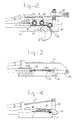
- this cable 11 is guided through connection cable 4 and emerges again at the application part 3, where it actuates a lever 25, as can be seen from Fig. 2.
- This lever 25 is connected via a pin 26 to a cutting blade 24.
- Magnet 10 can be actuated at specific defined and adjustable periods by means of control 7 or can be actuated automatically when switch -15 is released.
- the application part comprises, in addition to the handle 14, a support plate 17 which is fixedly connected thereto. As depicted in Fig. 3, a closure plate 18 is arranged on support plate 17. This closure plate is omitted in Fig. 2 for the sake of clarity.
- Ball-bearings 19, 20 and 21 are arranged in support plate 17 These ball-bearings are situated in the path of wire 12, which is supplied from store 5. Moreover, a protuberance 27 is arranged in the path of wire 12. As can be seen from Fig. 2, this protuberance interacts with ball-bearing 21 to effect turning of the wire. A further phase of operation is shown in Fig. 3. Cable 11 is not tensioned in either Fig. 2 or Fig. 3. However, in Fig. 4 it is tensioned, so that blade 24 is rotated and cuts through the spiral ring 30.
- Ring 30 may comprise one or more turns, depending on the wishes of the user. Moreover, by adjusting the exit opening from the support plate 17, it is possible to regulate the distance between two successive winds of the ring.
- the device according to the invention can be actuated using one hand. Since all the relatively heavy components of the device are situated in the remotely positioned box, the device is easy to handle.
- this box 6 may be provided with wheels or other means for displacement through a greenhouse, for example. It may be designed as a tubular truck. However, stationary applications are also conceivable.
- the device according to the invention makes it possible to obtain a considerable saving compared to conventional clamps. Firstly, it is possible to fix a greater number of rings per hour than when clamping as in the prior art. Moreover, a drawback of machines which operate using magazines containing clamps is that the magazines are constantly becoming empty. A very great length of wire can be arranged in the store according to the invention.
- a buffer mechanism is situated in the region of the store of the wire, in order to convert the dispensing of wire in strands into a gradually rotating motion of the wire wound onto a roll.
Landscapes
- Life Sciences & Earth Sciences (AREA)
- Botany (AREA)
- Environmental Sciences (AREA)
- Basic Packing Technique (AREA)
Claims (8)
- Dispositif (1) pour la fabrication d'une bague (30), par exemple pour la fixation d'une tige de plante (22) sur un support (23), comportant un mécanisme de transport pour un fil (12), des moyens destinés à faire tourner ledit fil comportant un passage courbe pour ledit fil afin d'obtenir une bague et des moyens de coupe (25) pour ledit fil, lesquels moyens de coupe sont disposés sur une partie de poignée (14), caractérisé en ce que ladite partie de poignée comporte une plaque de support (17) sur laquelle les moyens destinés à faire tourner ledit fil et les moyens de coupe sont disposés, lesdits moyens destinés à faire tourner ledit fil comportant une protubérance (27) disposée dans ladite plaque de support (17) prévue sur un côté du passage courbe et des moyens de palier (21) prévus sur l'autre côté du passage afin d'effectuer la rotation du fil, et le mécanisme de transport comportant un moteur de rotation qui entraíne le fil par l'intermédiaire de galets (8, 9).
- Dispositif selon la revendication 1, une réserve (5) pour le fil étant disposée dans un support (6) qui est relié à la partie de poignée par l'intermédiaire d'une ligne flexible (4).
- Dispositif selon l'une des revendications précédentes, au moins une partie du mécanisme de transport étant disposée dans ledit support.
- Dispositif selon l'une des revendications précédentes, lesdits moyens de coupe comportant une lame rotative (25).
- Dispositif selon la revendication 4, la lame étant disposée d'une manière alternative.
- Dispositif selon la revendication 2, dans lequel les moyens d'actionnement (10) pour la lame sont disposés dans le support.
- Dispositif selon la revendication 6, dans lequel les moyens d'actionnement exécutent un déplacement linéaire.
- Dispositif selon l'une des revendications précédentes, comportant au moins deux paliers à roulement, qui sont disposés dans le passage du fil (12).
Applications Claiming Priority (3)
| Application Number | Priority Date | Filing Date | Title |
|---|---|---|---|
| NL1003237A NL1003237C2 (nl) | 1996-05-30 | 1996-05-30 | Inrichting voor het vervaardigen van een ring. |
| NL1003237 | 1996-05-30 | ||
| PCT/NL1997/000308 WO1997044999A1 (fr) | 1996-05-30 | 1997-05-30 | Dispositif de production d'une bague |
Publications (2)
| Publication Number | Publication Date |
|---|---|
| EP0903976A1 EP0903976A1 (fr) | 1999-03-31 |
| EP0903976B1 true EP0903976B1 (fr) | 2003-10-08 |
Family
ID=19762944
Family Applications (1)
| Application Number | Title | Priority Date | Filing Date |
|---|---|---|---|
| EP97924382A Expired - Lifetime EP0903976B1 (fr) | 1996-05-30 | 1997-05-30 | Dispositif de production d'une bague |
Country Status (7)
| Country | Link |
|---|---|
| EP (1) | EP0903976B1 (fr) |
| AU (1) | AU2981097A (fr) |
| CA (1) | CA2256713A1 (fr) |
| DE (1) | DE69725439D1 (fr) |
| ES (1) | ES2205223T3 (fr) |
| NL (1) | NL1003237C2 (fr) |
| WO (1) | WO1997044999A1 (fr) |
Families Citing this family (4)
| Publication number | Priority date | Publication date | Assignee | Title |
|---|---|---|---|---|
| FR2780702B1 (fr) * | 1998-07-01 | 2000-09-22 | Creation E C B Et | Appareil pour attacher au moyen d'un lien souple un ou plusieurs objets, tels que des sarments de vigne |
| AU732515B2 (en) * | 1999-07-20 | 2001-04-26 | Nam-Sun Jho | A binding machine for gardening |
| DE60008687T2 (de) * | 2000-01-06 | 2005-02-03 | Etudes et Création E.C.B. Société à responsabilité Limitée à associé unique | Gerät zum Anbinden eines oder mehrerer Objekte, wie z.B. Rebtriebe |
| ITPN20050086A1 (it) * | 2005-11-28 | 2007-05-29 | Bortolussi Mollificio Srl | Procedimento di legatura di rami di piante, in particolare tralci di vite, ad un elemento di sostegno. |
Family Cites Families (3)
| Publication number | Priority date | Publication date | Assignee | Title |
|---|---|---|---|---|
| EP0136289A1 (fr) * | 1983-02-16 | 1985-04-10 | Daniel Schmidt | Outil pour enrouler un fil |
| FR2701739B1 (fr) * | 1993-02-18 | 1995-10-20 | Bemax | Pince a lier. |
| FR2738456B1 (fr) * | 1995-09-12 | 1997-10-24 | Pellenc Sa | Appareil pour la pose d'attaches, par exemple pour l'attachage de la vigne |
-
1996
- 1996-05-30 NL NL1003237A patent/NL1003237C2/nl not_active IP Right Cessation
-
1997
- 1997-05-30 WO PCT/NL1997/000308 patent/WO1997044999A1/fr not_active Ceased
- 1997-05-30 DE DE69725439T patent/DE69725439D1/de not_active Expired - Lifetime
- 1997-05-30 AU AU29810/97A patent/AU2981097A/en not_active Abandoned
- 1997-05-30 EP EP97924382A patent/EP0903976B1/fr not_active Expired - Lifetime
- 1997-05-30 ES ES97924382T patent/ES2205223T3/es not_active Expired - Lifetime
- 1997-05-30 CA CA002256713A patent/CA2256713A1/fr not_active Abandoned
Also Published As
| Publication number | Publication date |
|---|---|
| AU2981097A (en) | 1998-01-05 |
| ES2205223T3 (es) | 2004-05-01 |
| DE69725439D1 (de) | 2003-11-13 |
| WO1997044999A1 (fr) | 1997-12-04 |
| NL1003237C2 (nl) | 1997-12-03 |
| EP0903976A1 (fr) | 1999-03-31 |
| CA2256713A1 (fr) | 1997-12-04 |
Similar Documents
| Publication | Publication Date | Title |
|---|---|---|
| US7089713B2 (en) | Method and apparatus for stretch wrapping a load | |
| US20120292420A1 (en) | Reel assembly | |
| US4182235A (en) | Method and arrangement for binding round bales | |
| EP3752425B1 (fr) | Outil d'attache de câble portatif | |
| EP0903976B1 (fr) | Dispositif de production d'une bague | |
| JPS6313133Y2 (fr) | ||
| US5924209A (en) | Powered coping saw | |
| KR20110110415A (ko) | 결속테이프를 이용한 자동 다발묶음장치 | |
| US20170099780A1 (en) | Pruning shears | |
| US20030177646A1 (en) | High twig pruner | |
| US6546852B1 (en) | Method and machine for packaging skeins, shaped as rings, of a flexible, elongated element | |
| US4953598A (en) | Wire tying tool for concrete reinforcing steel | |
| KR20100044582A (ko) | 비닐랩을 이용한 가지접용 랩핑 장치 | |
| CN1050165A (zh) | 具有改进扭曲头的捆扎装置和设有该装置的尤其是供捆扎铁丝盘条的打捆机 | |
| KR101746914B1 (ko) | 결속테이프를 이용한 묶음장치 | |
| FR2676468A1 (fr) | Dispositif d'alimentation de ruban sur une machine a coudre. | |
| US4362096A (en) | Tying machine | |
| EP0058479B1 (fr) | Dispositif pour lier des emballages | |
| US6837156B2 (en) | Twist tie feed device | |
| CN202464190U (zh) | 一种管或线自动捆扎机 | |
| US5836137A (en) | Tying apparatus | |
| FR2480255A1 (fr) | Dispositif lance-feuillard automatique pour le ligaturage | |
| CN219786418U (zh) | 一种焊丝绕线切断机构 | |
| CN219294106U (zh) | 一种pe管材定长切割装置 | |
| WO2012098526A1 (fr) | Machine pour fermer des contenants souples |
Legal Events
| Date | Code | Title | Description |
|---|---|---|---|
| PUAI | Public reference made under article 153(3) epc to a published international application that has entered the european phase |
Free format text: ORIGINAL CODE: 0009012 |
|
| 17P | Request for examination filed |
Effective date: 19981127 |
|
| AK | Designated contracting states |
Kind code of ref document: A1 Designated state(s): BE CH DE ES FR GB IT LI NL |
|
| 17Q | First examination report despatched |
Effective date: 19990929 |
|
| APAB | Appeal dossier modified |
Free format text: ORIGINAL CODE: EPIDOS NOAPE |
|
| APAB | Appeal dossier modified |
Free format text: ORIGINAL CODE: EPIDOS NOAPE |
|
| APAD | Appeal reference recorded |
Free format text: ORIGINAL CODE: EPIDOS REFNE |
|
| APCB | Communication from the board of appeal sent |
Free format text: ORIGINAL CODE: EPIDOS OBAPE |
|
| APCB | Communication from the board of appeal sent |
Free format text: ORIGINAL CODE: EPIDOS OBAPE |
|
| APAB | Appeal dossier modified |
Free format text: ORIGINAL CODE: EPIDOS NOAPE |
|
| GRAG | Despatch of communication of intention to grant |
Free format text: ORIGINAL CODE: EPIDOS AGRA |
|
| GRAG | Despatch of communication of intention to grant |
Free format text: ORIGINAL CODE: EPIDOS AGRA |
|
| GRAH | Despatch of communication of intention to grant a patent |
Free format text: ORIGINAL CODE: EPIDOS IGRA |
|
| GRAH | Despatch of communication of intention to grant a patent |
Free format text: ORIGINAL CODE: EPIDOS IGRA |
|
| GRAA | (expected) grant |
Free format text: ORIGINAL CODE: 0009210 |
|
| AK | Designated contracting states |
Kind code of ref document: B1 Designated state(s): BE CH DE ES FR GB IT LI NL |
|
| PG25 | Lapsed in a contracting state [announced via postgrant information from national office to epo] |
Ref country code: LI Free format text: LAPSE BECAUSE OF FAILURE TO SUBMIT A TRANSLATION OF THE DESCRIPTION OR TO PAY THE FEE WITHIN THE PRESCRIBED TIME-LIMIT Effective date: 20031008 Ref country code: IT Free format text: LAPSE BECAUSE OF FAILURE TO SUBMIT A TRANSLATION OF THE DESCRIPTION OR TO PAY THE FEE WITHIN THE PRE;WARNING: LAPSES OF ITALIAN PATENTS WITH EFFECTIVE DATE BEFORE 2007 MAY HAVE OCCURRED AT ANY TIME BEFORE 2007. THE CORRECT EFFECTIVE DATE MAY BE DIFFERENT FROM THE ONE RECORDED.SCRIBED TIME-LIMIT Effective date: 20031008 Ref country code: CH Free format text: LAPSE BECAUSE OF FAILURE TO SUBMIT A TRANSLATION OF THE DESCRIPTION OR TO PAY THE FEE WITHIN THE PRESCRIBED TIME-LIMIT Effective date: 20031008 |
|
| REG | Reference to a national code |
Ref country code: GB Ref legal event code: FG4D |
|
| REG | Reference to a national code |
Ref country code: CH Ref legal event code: EP |
|
| REF | Corresponds to: |
Ref document number: 69725439 Country of ref document: DE Date of ref document: 20031113 Kind code of ref document: P |
|
| PG25 | Lapsed in a contracting state [announced via postgrant information from national office to epo] |
Ref country code: DE Free format text: LAPSE BECAUSE OF FAILURE TO SUBMIT A TRANSLATION OF THE DESCRIPTION OR TO PAY THE FEE WITHIN THE PRESCRIBED TIME-LIMIT Effective date: 20040109 |
|
| REG | Reference to a national code |
Ref country code: CH Ref legal event code: PL |
|
| REG | Reference to a national code |
Ref country code: ES Ref legal event code: FG2A Ref document number: 2205223 Country of ref document: ES Kind code of ref document: T3 |
|
| ET | Fr: translation filed | ||
| PLBE | No opposition filed within time limit |
Free format text: ORIGINAL CODE: 0009261 |
|
| STAA | Information on the status of an ep patent application or granted ep patent |
Free format text: STATUS: NO OPPOSITION FILED WITHIN TIME LIMIT |
|
| 26N | No opposition filed |
Effective date: 20040709 |
|
| APAH | Appeal reference modified |
Free format text: ORIGINAL CODE: EPIDOSCREFNO |
|
| PGFP | Annual fee paid to national office [announced via postgrant information from national office to epo] |
Ref country code: NL Payment date: 20110303 Year of fee payment: 15 |
|
| PGFP | Annual fee paid to national office [announced via postgrant information from national office to epo] |
Ref country code: FR Payment date: 20110607 Year of fee payment: 15 Ref country code: ES Payment date: 20110512 Year of fee payment: 15 |
|
| PGFP | Annual fee paid to national office [announced via postgrant information from national office to epo] |
Ref country code: BE Payment date: 20110531 Year of fee payment: 15 Ref country code: GB Payment date: 20110525 Year of fee payment: 15 |
|
| BERE | Be: lapsed |
Owner name: *VAN SCHIE SEBASTIANUS THEODORUS CORNELIS Effective date: 20120531 |
|
| REG | Reference to a national code |
Ref country code: NL Ref legal event code: V1 Effective date: 20121201 |
|
| GBPC | Gb: european patent ceased through non-payment of renewal fee |
Effective date: 20120530 |
|
| PG25 | Lapsed in a contracting state [announced via postgrant information from national office to epo] |
Ref country code: BE Free format text: LAPSE BECAUSE OF NON-PAYMENT OF DUE FEES Effective date: 20120531 |
|
| REG | Reference to a national code |
Ref country code: FR Ref legal event code: ST Effective date: 20130131 |
|
| PG25 | Lapsed in a contracting state [announced via postgrant information from national office to epo] |
Ref country code: NL Free format text: LAPSE BECAUSE OF NON-PAYMENT OF DUE FEES Effective date: 20121201 |
|
| PG25 | Lapsed in a contracting state [announced via postgrant information from national office to epo] |
Ref country code: FR Free format text: LAPSE BECAUSE OF NON-PAYMENT OF DUE FEES Effective date: 20120531 Ref country code: GB Free format text: LAPSE BECAUSE OF NON-PAYMENT OF DUE FEES Effective date: 20120530 |
|
| REG | Reference to a national code |
Ref country code: ES Ref legal event code: FD2A Effective date: 20130820 |
|
| PG25 | Lapsed in a contracting state [announced via postgrant information from national office to epo] |
Ref country code: ES Free format text: LAPSE BECAUSE OF NON-PAYMENT OF DUE FEES Effective date: 20120531 |