EP0903831A2 - Ladegerät und -system - Google Patents
Ladegerät und -system Download PDFInfo
- Publication number
- EP0903831A2 EP0903831A2 EP98307601A EP98307601A EP0903831A2 EP 0903831 A2 EP0903831 A2 EP 0903831A2 EP 98307601 A EP98307601 A EP 98307601A EP 98307601 A EP98307601 A EP 98307601A EP 0903831 A2 EP0903831 A2 EP 0903831A2
- Authority
- EP
- European Patent Office
- Prior art keywords
- secondary battery
- charging
- stage
- voltage
- current
- Prior art date
- Legal status (The legal status is an assumption and is not a legal conclusion. Google has not performed a legal analysis and makes no representation as to the accuracy of the status listed.)
- Withdrawn
Links
Images


Classifications
-
- H—ELECTRICITY
- H02—GENERATION; CONVERSION OR DISTRIBUTION OF ELECTRIC POWER
- H02J—ELECTRIC POWER NETWORKS; CIRCUIT ARRANGEMENTS OR SYSTEMS FOR SUPPLYING OR DISTRIBUTING ELECTRIC POWER; SYSTEMS FOR STORING ELECTRIC ENERGY
- H02J7/00—Circuit arrangements for charging or discharging batteries or for supplying loads from batteries
- H02J7/90—Regulation of charging or discharging current or voltage
- H02J7/92—Regulation of charging or discharging current or voltage with prioritisation of loads or sources
-
- H—ELECTRICITY
- H02—GENERATION; CONVERSION OR DISTRIBUTION OF ELECTRIC POWER
- H02J—ELECTRIC POWER NETWORKS; CIRCUIT ARRANGEMENTS OR SYSTEMS FOR SUPPLYING OR DISTRIBUTING ELECTRIC POWER; SYSTEMS FOR STORING ELECTRIC ENERGY
- H02J7/00—Circuit arrangements for charging or discharging batteries or for supplying loads from batteries
- H02J7/50—Circuit arrangements for charging or discharging batteries or for supplying loads from batteries acting upon multiple batteries simultaneously or sequentially
Definitions
- the present invention relates to a charging system for a secondary cell and to a secondary cell charging apparatus, and more specifically to a charging system and secondary cell charging apparatus which, in charging a secondary cell, are capable of causing a secondary cell to achieve a charged state that is close to a full charge, and also of causing the secondary cell to operate with good efficiency at all times, so that a long life is maintained for the secondary cell.
- secondary cells such as lead batteries, nickel-cadmium batteries, nickel-hydrogen batteries, nickel-zinc batteries, and lithium ion batteries are recharged many times over their useful lifetime.
- the recharging process requires as much as several hours. That is, in the prior art process of recharging the above-noted secondary cells, 6 hours or in extreme cases even 16 hours were required to perform the charging operation, and even with what was called a quick charge, 1 to 2 hours was required.
- Voltage regulation of lithium ion batteries is particularly difficult, and if the charging process is allowed to proceed so as to exceed a priorly established upper voltage limit, ions precipitate, so that not only does the battery lose its functionality, but also a high temperature is generated, this leading to the danger of an explosion of the battery.
- the voltage output waveform might not necessarily match in sequence and magnitude the stored information, so that it is not possible to perform a precise charging and recharging operation, this making it difficult to perform a high-speed charging operation.
- a method is also known for detecting the temperature of a secondary battery, and controlling the charging process.
- an object of the present invention is to improve on the drawbacks of the prior art as noted above, by providing a charging processing system which, when performing an operation of charging various secondary batteries as noted above, accurately detects the time of the secondary battery reaching the fully charged condition or the condition thereof, makes it possible to maintain the secondary battery at the fully charged condition at all times, and to provide a charging processing system and apparatus therefor which, when performing the charging of a secondary battery, enable efficient charging processing.
- an object of the present invention is to provide a charging processing system which particularly enables charging of lithium ion batteries and lead batteries within 100 minutes, and charging of other secondary battery types in from ten to several tens of minutes.
- the present invention has the following basic technical constitution. Specifically, in a first aspect of a charging method for secondary batteries, including lithium ion batteries, according to the present invention, at a first stage a prescribed charging current C1, expressed as a C rate, is supplied to the secondary battery, the output voltage of the secondary battery being monitored and, when the output voltage of the secondary battery reaches a pre-established voltage value, transition is made to a second stage, at which a charging current C2 which is 1/N of C1 (where N is an arbitrary integer value or a real value with a decimal part), which was the current used in the first stage, is supplied to the secondary battery and, when the output voltage of the secondary battery reaches a pre-established voltage that is one and the same with the above-noted pre-established voltage, a transition is made to a third stage, at which a charging current C3 which is 1/M of C2 (where M is an arbitrary integer value or a real value with a decimal part and can also be equal to N
- this is a method in which the configuration is such that a protective circuit is provided so that a voltage greater than the pre-established voltage value is not applied to the output terminal of the secondary battery.
- a second aspect of a charging method for secondary batteries at a first stage constant current charging of the secondary battery is performed, during which time period the output voltage of the secondary battery gradually increases and, when the output voltage of the secondary battery reaches a pre-established voltage value, a switch is made to constant voltage charging operation, during which time period the charging current is caused to decrease gradually and, when this charging current falls below a pre-established current value, the charging operation with respect to the secondary battery is caused to stop.
- this is a method in which the configuration is such that a protective circuit is provided so that a voltage greater than the pre-established voltage value is not applied to the output terminal of the secondary battery.
- a secondary battery insertion part into which a plurality of secondary battery packs are simultaneously mounted, a voltage/current detection means which separately detects the output voltage from and the charging current supplied to of each of the secondary batteries provided in the insertion secondary battery pack insertion part, a constant-current source, a constant-voltage source, a charging current supplying means which selectively supplies a charging current to the plurality of secondary batteries, and a charging processing control means, the charging processing control means being provided with a charging operation stage identification means that a first stage in which the secondary batteries receive a charging operation from the constant-current source and a second stage in which the secondary batteries receive a charging operation from the constant-voltage source, the configuration of the above being arranged so that, responsive to voltage value or charging current value detected each of the secondary battery packs, at a point in time at which the first stage charging operation with respect to a first secondary battery is started, the charging operation with respect to a second secondary battery is not started, and at a
- a charging processing system and secondary battery charging apparatus is capable of executing high-speed charging of a secondary battery so as to achieve nearly a fully charged condition in a short period of time.
- secondary batteries such as lithium ion batteries
- sensing and controlling the charged condition accurately it provides a charging processing method and apparatus that safely and reliably achieves a fully charged condition.
- by performing charging operation simultaneously with respect to a plurality of secondary batteries it enables execution of overall charging of the secondary batteries in a short period of time.
- the inventor of the present invention understands the problems involved in performing a charging operation with respect to a secondary battery in the past, and to achieve a charging method and a charging apparatus that is capable of achieving high charging efficiency and reliable and safe charging to 100% in a short period of time, the inventor conceived of the above-noted secondary battery charging method and charging apparatus having the objects described above.
- a prescribed charging current C1 express as a C rate, is supplied to a secondary battery, the output voltage of the secondary battery being monitored and, when the output voltage of the secondary battery reaches a pre-established voltage value, transition is made to a second stage, at which a charging current C2 which is 1/N of C1 (where N is an arbitrary integer value or a real value with a decimal part), which was the current used in the first stage, is supplied to the secondary battery and, when the output voltage of the secondary battery reaches a pre-established voltage that is one and the same with the above-noted pre-established voltage, a transition is made to a third stage, at which a charging current C3 which is 1/M of C2 (where M is an arbitrary integer value or a real value with a decimal part and can also be equal to N), which was the current used in the second stage, is supplied to the secondary battery and thereafter the same is performed, so that each time the charging current C2 which is 1/N of C1 (where N is an arbitrary integer value or
- the configuration is such that, in the case in which the charging current supplied to the secondary battery drops below a prescribed amount, the charging operation with respect to the secondary battery is stopped and, in using a charging method which employs a switching regulator which causes the amount of this charging current to vary in accordance with the duty cycle of one pulse, this is a method in which the configuration is such that a protective circuit is provided so that a voltage that is greater than the pre-established voltage value is not applied to the output terminal of the secondary battery.
- the basic charging method with respect to a secondary battery according to the present invention is the method of charging by the step-down method, as already noted by the applicant in this case, in the Japanese Patent Application H7-183173, this method being particular superior with respect to lithium ion batteries.
- the present invention is an improvement which enables the above-noted step-down method to be employed with better efficiency, and, in consideration of the fact that, there is a dangerous condition that occurs in particular when a high charging voltage that exceeds a pre-established voltage value is applied to a lithium battery, an investigation was performed as to how to accurately stop the charging operation with respect to a secondary battery in a condition that is close to the rated voltage value, this investigation obtaining the favorable results disclosed herein.
- a switching regulator is used, the duty cycle of a pulse voltage that is output from the switching regulator being varied, thereby varying the value of charging current and charging voltage that are applied to the secondary battery.
- this ripple voltage is not much of a problem.
- this ripple voltage can exceed the maximum allowable charging voltage of the secondary battery, in which case the above-noted problem arises.
- step-down method which is the basic technical idea of the present invention, is used, this being superior from the standpoint of reducing the chance that the ripple voltage will exceed the maximum allowable charging voltage of the secondary battery, even if a switching regulator is used, because the maximum allowable voltage value of the secondary battery is approached for each stage at the end of each step, this danger is not entirely eliminated.
- a control zone is established, this being ⁇ 1% with respect to the maximum voltage value of the secondary battery that is recommended by the manufacturer thereof, and in the case in which the charging voltage of the secondary battery reached to within this range, a judgment is made that the charging voltage value has reached a pre-established voltage value, this resulting in the next step-down operation.
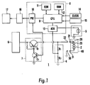
- Th charging processing operation with respect to the secondary battery for example as shown in Fig. 1, can be carried out by an apparatus that is one and the same as the charging apparatus that is proposed by the block diagram of Fig. 5 and noted in the Japanese Patent Application H7-183173, which was filed by the applicant which is filing this application.
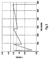
- Fig. 3 is a graph which shows an example of the case of performing a charging operation with respect to the secondary battery shown in Fig. 1 and Fig. 2 using the charging processing control according to the present invention. This shows the case of charging a lithium battery for which the manufacture recommends a maximum allowable voltage of 4.2 V, under the condition of 3.6 V/750 mAh. Charging was done with the allowable range of charging voltage of this lithium battery set to ⁇ 1% with respect to 4.2 V.
- a switch is made to constant-voltage charging operation, during which period the charging current is caused to decrease gradually.
- the configuration is such that when the amount of the charging current falls below a pre-established current value, the charging of the secondary battery is stopped.
- a switching regulator is used to vary the charging current supplied to the secondary battery, in accordance with the duty cycle of one pulse.
- an allowable range is set, similar to the above-noted example and, in the case in which the output voltage value of the secondary battery is within the range of ⁇ 1% with respect to the output voltage rating value of the secondary battery, the charging voltage with respect to the secondary battery is adjusted and by the switching regulator so that it is reduced.
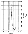
- the change in the charging voltage value of the secondary battery, based on charging operation according to the present invention, is shown in Fig. 4, from which it is clear that, although the charging voltage value of the secondary battery is quite low at first, it quickly enters a range of ⁇ 1% with respect to 4.2 V, after which it is reliably controlled so that it does not exceed 4.2 V.
- a protective circuit is provided at an output terminal of the secondary battery of either of the previously described examples, so that a voltage which exceeds a pre-established voltage value is not applied to the secondary battery.
- a protective circuit that has a limiter function or a switching function is provided at the power supply input/output terminal part of the secondary battery, so that a voltage that exceeds the allowable value is not applied to the secondary battery.
- the circuit configuration of the above-noted protective circuit is not limited to a particular configuration.
- This protective circuit can be, for example, a known limiter circuit, or a circuit formed by the combination of a voltage detection means and a switching means.
- the above-noted protective circuit be disposed at the location that is indicated as 20 in Fig. 1.
- the secondary battery 2 is mounted in a prescribed charging apparatus 1, it is desirable that this be configured so that it is connected in series with the power supply terminal 22 of the charging apparatus 1 and the terminal part 23 of the secondary battery.
- the configuration is such that the external connection terminal parts 21 and 31 of the secondary battery pack 40 are connected to the power supply terminal 22 and a ground terminal 32, respectively, and the protective circuit 20 is connected in series between the first external connection terminal 21 of the secondary battery pack 40 and the output terminal 23 of the secondary battery.
- the characteristic internal resistance of the protective circuit acts so that there is a voltage drop based on that internal resistance in the protective circuit.
- This internal resistance of the protective circuit depends upon the configuration of the protection circuit, and also differs between manufacturers. Furthermore, even for protective circuits having the same configuration, variations between individual components thereof will prevent coincide between the overall internal resistances thereof.
- another specific example of the present invention provides a method for performing accurate charging processing, even if it is not possible to determine accurately the internal resistance of the protective circuit.
- the basic technical concept is one by which the configuration is such that, when supplying a prescribed charging voltage to the output terminal part 23 of the secondary battery from the power supply terminal 22 of the charging apparatus 1, a voltage which is compensated by the amount of the voltage drop of the protective circuit 20 is applied to the output terminal 23 of the secondary battery 2 from the power supply terminal 23 of the charging apparatus 1.
- Fig. 5 (A) in addition to providing a third terminal part 50 which is connected to the output terminal 23 of the secondary battery 2 separately from the external connection terminal 21 that is connected to the protective circuit 20 and, as shown in Fig. 5 (B), by providing an auxiliary terminal 51 that connects with the third terminal 50 of the secondary battery 2 on the charging apparatus side, the true output voltage value of the secondary battery 2 at the charging apparatus can be monitored via this third terminal part 50 and auxiliary terminal 51.
- the true output voltage value of the secondary battery 2 that is detected by the auxiliary terminal 51 is compared with the target reference voltage value Vref of the secondary battery, the difference therebetween being taken, voltage compensation being performed with respect to the voltage value that is applied to the protective circuit 20, so that this difference component made zero.
- the secondary battery pack 40 is provided with a first terminal part 21 forms an input terminal of the protective circuit 20 that is connected to the output terminal part 23 of the secondary battery 2, a second terminal part 31 that is connected to a negative terminal part of the secondary battery 2, and a third terminal part 50 that is directly connected to the output terminal part 23 of the secondary battery 2.
- a positive terminal part 22 and a negative terminal part 32 which make physical contact, respectively, with the first and second terminal parts 21 and 31 provided on the secondary battery pack 2, are provide, and additionally an auxiliary terminal 51 is provided which makes physical contact with the third terminal part 50.
- a control means 55 is additionally provided which, in response to the voltage value of the output terminal part 23 of the secondary battery 2 that is detected by the auxiliary terminal part 51, performs control so that a voltage form the positive terminal part 23 that is compensated for the voltage drop of the protective circuit 20 is applied to the first terminal part 21.
- the above-noted target reference voltage value Vref can be established as the maximum allowable voltage value recommended by the manufacturer of the secondary battery, and using the above-noted step-down method, it is desirable that this target reference voltage value Vref be variably and selectively set beforehand as a plurality of different voltage values.
- the above-noted control means 55 in the above-noted example of the present invention is formed, for example, by a voltage adjustment means 56 that is connected to a power supply (not shown in the drawing), a current detection means 57 that is connected to the voltage adjustment means, and that has its output connected to the positive terminal part 22, a voltage comparison means 58 that is connected to the auxiliary terminal part 51 and connected to a prescribed reference voltage source Vref, an error amplification means 59 that has its input connected to the output of the voltage comparison means 58 and which has its output connected to the voltage adjustment means 56, and a maximum current control means 60 that has its output connected to the current detection means 57 and its output connected to the voltage adjustment means 56.
- the true voltage value of the output terminal 23 of the secondary battery 2 that is output at the third terminal part 50 of the secondary battery 2 is first monitored at the auxiliary terminal 51, and a comparison is performed between this monitored voltage value and the above-noted target reference voltage value Vref by the voltage comparison means 58.
- the target reference voltage value Vref can be set, for example, to 4.2 V.
- the required amount of charging current is constantly being supplied from an appropriate power supply (not shown in the drawings) to the first terminal part 21 of the secondary battery pack 40 via the voltage adjustment means 56
- the charging voltage of the secondary battery is increased with a constant current until it reaches a pre-established prescribed voltage, during which time period whether or not a constant current is flowing is monitored by the current detection means 57, the results therefrom being reported to the maximum current control means 60.
- the voltage adjustment means 56 in response to the difference value, which is the output of the error amplification means 59, executes operation so as to reduce the amount of current, so that this difference amount is made zero.
- yet another example of the present invention is a method of performing charging using a charging apparatus into which a plurality of secondary batteries are mounted simultaneously, one aspect thereof being a method of charging a secondary battery, wherein at a first stage a prescribe charging current C1, which is expressed as a C rate, is supplied to the secondary battery, the output voltage of the secondary battery being monitored and, when the output voltage of the second battery reaches a pre-established voltage value, transition is made to a second stage, at which a charging current C2 which is 1/N of N (where N is an arbitrary integer value or a real value with a decimal part), which was the current used in the first stage, is supplied to the secondary battery and, when the output voltage of the secondary battery reaches a pre-established voltage that is one and the same with the above-noted pre-established voltage, a transition is made to a third stage, at which a charging current C3 which is 1/M of C2 (where M is an arbitrary integer value or a real value with a decimal part and can also be
- a secondary battery charging apparatus in which a method of stopping the charging processing with respect to the secondary battery in the case in which the charging current falls below a pre-established current value, or at the point in time at which a pre-established number of stages have elapsed, or if the charging current drops below a prescribed value, in performing charging of a plurality of secondary batteries using the same charging apparatus, at the point in time at which the first stage charging operation with respect to a first secondary battery is started, the charging operation with respect to a second secondary battery is not started, and at a point in time at which a transition is made to a second stage of charging operation with respect to the first secondary battery, a first preparatory charging operation with respect to the second secondary battery is started, whereby a charging current is supplied thereto, this current being a value that is the charging current supplied in the second stage to the first secondary battery subtracted from the maximum charging current in the first state which is supplied to the first secondary battery, and at a point in time at which a transition is made to a third stage of charging operation with respect
- the secondary battery charged by constant-current charging operation, during which time period the output voltage of this secondary battery gradually increases and, when the output voltage value of the secondary battery reaches a prescribed voltage value, the second stage is entered, in which stage a switch is made to constant-voltage charging operation, during which time period the charging current is caused to decrease gradually and, when the amount of the charging current falls below a pre-established current value, the charging operation with respect to the secondary battery is ended.
- a charging apparatus that executes a secondary battery charging method as noted above, when charging a plurality of secondary batteries with one and the same charging apparatus, at a point in time at which the first stage charging operation with respect to the first secondary battery is started, the charging operation with respect to the second secondary battery is not started and, at a point in time at which a transition is made to the second stage of charging with respect to the first secondary battery, a preparatory charging operation is started with respect to the second secondary battery by supplying thereto a charging current that is the charging current that is supplied to the first secondary battery in the second stage subtracted from the maximum charging current in the first stage that is supplied to the first secondary battery, and at the point in time at which the charging operation with respect to the first secondary battery is completed, the preparatory charging operation with respect to the second secondary battery is stopped, simultaneously with which the first stage of charging operation with respect to the second secondary battery is started, after which the second stage of charging operation with respect to the first secondary battery is executed.
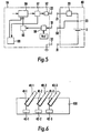
- the specific example of the charging apparatus 100 according to the present invention is provided with, for example as shown in Fig. 6 and Fig. 7, a plurality of secondary battery insertion parts 41-1, 41-2, and 41-3, into which a plurality of secondary battery packs 40-1, 40-2, and 40-3 are simultaneously mounted, this apparatus also having voltage and current detection means 73-1, 73-2, and 73-3, which separately detect the output voltage of the secondary batteries 2-1, 2-2, and 2-3 that are provided in the secondary battery insertion parts 41-1, 41-2, and 41-3, respectively and the charging current supplied to the secondary batteries 2-1, 2-2, and 2-3, constant-current control means 74-1, 74-2, and 74-3, non-constant-current control means 75-1, 75-2, and 75-3, charging current selection/supply means 76-1, 76-2, and 76-3 which selectively supply a constant current or a non-constant current to the secondary batteries 2-1, 2-2, and 2-3, respectively, which are disposed in the plurality of secondary battery insertion parts, and
- the charging current control means 77 has within it a program which operates in response to the first stage, in which the secondary battery is charged by a constant current and the second stage, in which the secondary battery is charged by a constant voltage and, in response to a voltage value or charging current value detected from the secondary battery pack, whereby at the point at which the first stage of charging the first secondary battery starts, the charging of the second secondary battery is not started, and at the point at which a transition is made to the second stage of charging with respect to the first secondary battery, a first preparatory charging operation with respect to the second secondary battery is started, by supplying a charging current thereto which is the charging current supplied in the second stage to the first secondary battery subtracted from the maximum charging current supplied in the firsts stage to the first secondary battery.
- either a second preparatory charging operation with respect to the second secondary battery is stared, by supplied a charging current thereto which is the charging current in the third stage with respect to the first secondary battery subtracted from the maximum charging current in the first stage that is supplied to the first secondary battery, or control is performed so as to repeat the charging operations so that the first stage of charging with respect to the second secondary battery is started.
- the charging current selection/supply means 76-1, 76-2, and 76-3 are formed by appropriate switching circuits, and are connected to the constant-current control means 74-1, 74-2, 74-3 and to the non-constant-current control means 75-1, 75-2, and 75-3 and, in response to a control signal that is output in response to an output value of the current detection means and voltage detection means to be described later, execute operation so as to establish whether the secondary battery 2 is to be supplied with a constant current, supplied with a non-constant current, or be completely cut off from current.
- the voltage/current detection means 73-1, 73-2, and 73-3 in this example are formed by the current detection means 71-1, 71-2, and 71-3 and the voltage detection means 72-1, 72-2, and 72-3, respectively.
- the current detection means 71-1, 71-2, and 71-3 monitor the current value being supplied to the secondary batteries 2-1, 2-2, and 2-3, respectively, and the outputs of these are connected to the comparison means 79-1, 79-2, and 79-3, respectively, which are in turn connected to the storage means 78-1, 78-2, and 78-3, respectively, which store a minimum current value for the purpose of judging whether or not it is time to stop the operation of charging the secondary batteries 2-1, 2-2, and 2-3, respectively, these comparison means 79-1, 79-2, and 79-3 making a judgment as to whether the current value supplied to the secondary batteries 2-1, 2-2, and 2-3, respectively, is a lower current value than a pre-established minimum current value, and these comparison means 79-1, 79-2, and 79-3
- the voltage detection means 72-1, 72-3, and 72-3 monitor the charging voltage of the secondary batteries, and a comparison is made by the comparison means 81-1, 81-2, and 81-3, respectively, between the battery voltage and a pre-established reference voltage value Vref, and if the charging voltage of the secondary batteries 2-1, 2-2, and 2-3, respectively, exceeds a pre-established target reference voltage value Vref, the comparison means 81-1, 81-2, and 81-3, respectively, output a signal S3 to the stitching circuits 76-1, 76-2, and 76-3, respectively, causing the circuits to be driving so that a switch is made from charging with a constant current to charging with a non-constant current.
- the signal S2 passes through, for example, the error amplification means 82-1, and then supplied to the non-constant-current control means 75-1, 75-2, and 75-3, these non-constant-current control means 75-1, 75-2, and 75-3 performing adjustment of the output current so that the difference value is made zero.
- non-constant-current control means 75-1, 75-2, and 75-3 has a function which, in response to the current supply stopping signal S1 from another secondary battery pack insertion part, subtracts the charging current being currently used in other secondary battery insertion parts from a pre-established prescribed current value, and outputs this difference value current.
- the charging current selection/supply means 76-1, 76-2, and 76-3 which are formed by switching circuits, each have input to them the charging stopping signal S1 from the other secondary battery insertion parts and, in response to a condition in which the charging operation at the other secondary battery insertion parts is stopped, these charging current selection/supply means 76-1, 76-2, and 76-3, as will be described below, are configured so as to start a first stage charging operation after a preparatory charging operation.
- Fig. 8 is a timing diagram that shows the case in which a plurality of secondary batteries that are each charged individually. As is clear from Fig. 8, when the first secondary battery pack 40 is first inserted into the charging apparatus, at the first stage P1 charging is done by constant current, and at the subsequent stage P2, charging is done by constant voltage.
- the other secondary battery packs 40-2 and 40-3 do not participate in the charge at all, and it is only after the completion of the charging operation with respect to the first secondary battery pack 40-1 that the second secondary battery pack 40-2 is inserted, whereupon the prescribed charging operation with respect to the second secondary battery pack 40-2 is started.
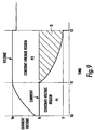
- a pre-established constant current Ic is supplied to the secondary battery, thereby starting the charging operation.
- the charging voltage of this secondary battery rises, and at time T1, the charging voltage reaches a pre-established prescribed voltage Ve.
- the above-noted period of time is known as the constant-current charging region, this being defined with regard to the present invention as the P1 charging stage.
- the above-noted period of time is known as the constant-voltage charging region, this being defined with regard to the present invention as the P2 charging stage.
- the charging apparatus in the second stage of charging processing, although the charging apparatus is capable of supplying the maximum current Ic using in the first stage for charging, by performing constant-voltage charging, the amount of current supplied is reduced, the shaded region shown in Fig. 9 representing the amount of reserve charging capacity of the power supply.
- the above-noted principle is applied to perform simultaneous charging of a plurality of secondary batteries.
- this description is for the case in which three secondary battery packs, 40-1, 40-2, and 40-3 are provided in a single charging apparatus 100, these being charged simultaneously.
- the charging control means 77 selects the first secondary battery insertion part 41-1, and performs constant-current/constant-voltage charging of the secondary battery pack 40-1.
- a prescribed voltage is supplied to the constant-current control means 74-1 from the constant-voltage power supply 70, a pre-established maximum allowable current being supplied from the constant-current control means 74-1 to the secondary battery, the first charging stage P1 starting and continuing until time T1.
- This reference voltage value Vref is set to, for example, 4.2 V in the case in which the secondary battery 2-1 is a lithium battery.
- a charging stage switching signal S3 is output to the charging current selection/supply means 76-1 from the comparison means 81-1, the charging current selection/supply means 76-1 being thereby switched to constant-voltage charging operation, at which point the second charging stage P2 starts.
- the charging current that is supplied to the secondary battery 2-1 from the non-constant-current control means 75-1, as noted above, is monitored by the current detection means 71-1, this charging current is compared at the comparison means 79-1 with a minimum charging current for the purpose of stopping the charging operation, this having been stored in a prescribed storage means 78-1. If the charging current value has become smaller than the above-noted minimum charging current value, a charging stopping signal S1, which stops the charging, is output to the charging current selection/supply means 76-1, thereby stopping the supply of current to the secondary battery 2-1, and this T2 point in time the charging operation with respect to the secondary battery 2-1 is completed.
- this charge stage switching signal S3 is also applied to the charging current selection/supply means 76-2 in the circuit that controls the first secondary battery pack 40-2, this charging current selection/supply means thereupon activating the non-constant-current control means 75-2 so as to start a preparatory charging operation.
- a preparatory charging operation is done with respect to the secondary battery 2-2 by the constant-current, this current being a difference value current obtained at the non-constant-current control means 75-2 by subtracting from the pre-established maximum allowable current value output from the constant-current control means 74-2 the actual current value that is output from the non-constant-current control means 75-1. Therefore, as shown in Fig. 10, during the preparatory charging time period between the point T1 and point T2, although the charging voltage of the secondary battery 2-2 increases, it does not increase to some determined level of charging voltage.
- the charging current selection/supply means 76-2 is switched so as to enable execution of constant-current charging, the above-noted constant current being supplied to the secondary battery 2-2 from the constant-current control means 74-2, thereby starting the first charging stage with respect to the secondary battery 2-2 at the time T2.
- a charging stage switching signal S3 that is output from the comparison means 81-2 is also applied to the charging current selection/supply means 76-3, which controls the secondary battery 2-3, so that this charging current selection/supply means 76-3 activates the non-constant-current control means 75-3 in the same manner as described above, thereby causing the start of a preparatory charging operation.
- the secondary battery 2-1 which is already completely charged, is removed from the secondary battery pack 40-1, a new secondary battery 2-4 that requires charging being inserted, and at this point a preparatory charging operation with respect to this new secondary battery 2-4 begins.
- the current values taken from the above-noted constant-voltage source 70 are all and always the same, this value being the same as when charging a single battery.
- the usage ratio of the power supply is 100%, enabling a system with superior cost performance.
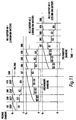
- Fig. 11 is a timing diagram that shows the case of applying the above-noted example to the step-down method.
- the step-down method is set in four stages
- the first stage corresponds to the preparatory charging operation
- the second through fourth stages correspond to constant-voltage charging operations.
- the difference current value between the maximum current value used in the first stage and the current values used in each of the second through fourth stages is used as the current for preparatory charging.
- the period from the point at which the charging operation with respect to the first secondary battery 2-1 transitions to the second stage until it reaches the fourth stage is the preparatory charging period with respect to the first secondary battery 2-1, and at the point at which the charging operation with respect to the first secondary battery 2-1 ends, the first stage charging operation with respect to the second secondary battery 2-2 starts.
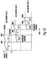
- Fig. 12 is a timing diagram that shows the case of performing a charging operation similar to the above-noted operation, in particular with respect to a nickel-cadmium secondary battery or a nickel-hydrogen secondary battery.
- control that is performed is different that the earlier-described example.
- a nickel-cadmium secondary battery or a nickel-hydrogen secondary battery because of the characteristics of the battery, because of gas that is generated within the battery at the end of the charging operation, it is preferable to reduce the charging current to the battery early.
- the charging current is reduced, the amount of this current reduction being used to perform preparatory charging of the next secondary battery.
- Yet another aspect of the present invention of a secondary battery charging method is a storage medium in which is stored a program for execution by a computer of steps of a method to charge a secondary battery, according to which steps, at a first stage a prescribed charging current C1, expressed as a C rate, is supplied to the secondary battery, the output voltage of the secondary battery being monitored and, when the output voltage of the secondary battery reaches a pre-established voltage value, transition is made to a second stage, at which a charging current of C2 which is 1/N of C1 (where N is an arbitrary integer value or a real value with a decimal part), which was the current used in the first stage, is supplied to the secondary battery and, when the output voltage of the secondary battery reaches a pre-established voltage value that is one and the same with the above-noted pre-established voltage value, a transition is made to a third stage, at which a charging current C3 which is 1/M of C2 (where M is an arbitrary integer value or a real value with a deci
- a charging apparatus which executes charging of a secondary battery, in which in the case in which the charging current drops below a pre-established prescribed current value, or when a pre-established prescribed number of stages have elapsed the charging of the secondary battery is stopped, when charging a plurality of secondary battery simultaneously using one and the same charging apparatus, at the point at which the first stage of charging the first secondary battery is started, the charging of the second secondary battery is not started and, at the point at which a transition is made to the second stage of charging the first secondary battery, a first preparatory charging operation is started with respect to the second secondary battery, by supplying thereto a current that is the charging current that is supplied in the second stage of charging to the first secondary battery subtracted from the maximum charging current in the first charging step with respect to the first secondary battery.
- a secondary preparatory charging of the second secondary battery is started, by supplying a charging current thereto which is the charging current supplied to the first secondary battery in the third stage subtracted from the maximum charging current supplied in the first stage of charging of the first secondary battery. Thereafter the same operations are performed and, when the charging of the first secondary battery proceeds to the next stage, a charging current that is the charging current supplied to the previous secondary battery in the next stage subtracted from the maximum charging current in the first stage to the first secondary battery is applied to the second secondary battery, a plurality of preparatory charging operations being performed until the charging operations with respect to the first secondary battery are completed, at which point the main charging operation with respect to the second secondary battery is started.
- Yet another aspect is a storage medium in which is stored a program for execution by a computer of steps of a method for execution by a computer of a method to charge a second battery, according to which steps, in a charging apparatus in which at a first stage a secondary battery is charged by means of constant-current charging, during which time the output voltage of the secondary battery gradually rises and, when the output voltage of the secondary battery reaches a pre-established prescribed voltage value, the second stage is entered, in which a switch is made to constant-voltage charging, during which time the charging current is caused to decrease gradually and, when the amount of charging current falls below a pre-established prescribed current value, in charging a plurality of secondary battery simultaneously with one and the same charging apparatus, at the point at which the first stage of charging the first secondary battery is started, the charging of the second secondary battery is not started and, at the point at which a transition is made to the second stage, preparatory charging is started with respect to the second secondary battery by supplying thereto a charging current that is the charging current supplied to the first secondary battery
- the present invention provides a charging system that is capable of achieving a charging time of 100 minutes or less, and with regard to other types of secondary batteries, is capable of completing the charging operation in a time ranging from over ten to several tens of minutes.
Landscapes
- Engineering & Computer Science (AREA)
- Power Engineering (AREA)
- Charge And Discharge Circuits For Batteries Or The Like (AREA)
- Secondary Cells (AREA)
Applications Claiming Priority (3)
| Application Number | Priority Date | Filing Date | Title |
|---|---|---|---|
| JP25466797 | 1997-09-19 | ||
| JP9254667A JPH1197074A (ja) | 1997-09-19 | 1997-09-19 | 充電方法及び充電装置 |
| JP254667/97 | 1997-09-19 |
Publications (2)
| Publication Number | Publication Date |
|---|---|
| EP0903831A2 true EP0903831A2 (de) | 1999-03-24 |
| EP0903831A3 EP0903831A3 (de) | 2000-08-30 |
Family
ID=17268200
Family Applications (1)
| Application Number | Title | Priority Date | Filing Date |
|---|---|---|---|
| EP98307601A Withdrawn EP0903831A3 (de) | 1997-09-19 | 1998-09-18 | Ladegerät und -system |
Country Status (4)
| Country | Link |
|---|---|
| EP (1) | EP0903831A3 (de) |
| JP (1) | JPH1197074A (de) |
| CN (1) | CN1157832C (de) |
| TW (1) | TW408509B (de) |
Cited By (4)
| Publication number | Priority date | Publication date | Assignee | Title |
|---|---|---|---|---|
| EP1355402A3 (de) * | 2002-03-27 | 2006-10-25 | Fuji Jukogyo Kabushiki Kaisha | Verfahren zur Ladung einer Speicherbatterie |
| EP1821383A3 (de) * | 2006-02-16 | 2012-08-01 | Summit Microelectronics, Inc. | Batterieladegerät |
| EP2568569A3 (de) * | 2011-09-12 | 2014-08-13 | Panasonic Corporation | Ladegerät |
| US9490642B2 (en) | 2012-06-07 | 2016-11-08 | Lg Chem, Ltd. | Charging method of secondary battery with constant current using high charge rate |
Families Citing this family (30)
| Publication number | Priority date | Publication date | Assignee | Title |
|---|---|---|---|---|
| JP5197904B2 (ja) * | 2001-09-27 | 2013-05-15 | 株式会社東芝 | 非水電解液二次電池パックの充電方法 |
| JP4137496B2 (ja) * | 2002-04-15 | 2008-08-20 | 富士通株式会社 | 残量予測方法 |
| KR101201110B1 (ko) | 2006-04-11 | 2012-11-13 | 삼성에스디아이 주식회사 | 전지 팩의 충전 장치 및 그 방법 |
| JP2007288982A (ja) * | 2006-04-20 | 2007-11-01 | Nec Saitama Ltd | 充電回路およびその充電方法 |
| US7973515B2 (en) * | 2007-03-07 | 2011-07-05 | O2Micro, Inc | Power management systems with controllable adapter output |
| KR20140129349A (ko) | 2007-12-10 | 2014-11-06 | 바이엘 헬쓰케어, 엘엘씨 | 배터리로 전원공급되는 체액 분석물질 측정기의 고속 충전 및 전원 관리 방법 |
| JP5137603B2 (ja) * | 2008-01-31 | 2013-02-06 | パナソニック株式会社 | アルカリ蓄電池の充放電制御方法および充放電制御システム |
| JP5532331B2 (ja) * | 2010-09-29 | 2014-06-25 | 日立工機株式会社 | 充電装置 |
| EP2741395B1 (de) * | 2011-10-04 | 2018-09-26 | LG Chem, Ltd. | Vorrichtung und verfahren zum aufladen einer batterie |
| KR101375158B1 (ko) * | 2011-11-17 | 2014-03-17 | 주식회사 샤인 | 전극 조립체, 이의 제조 방법, 및 전지의 충전 및 방전 방법 |
| TWI479719B (zh) * | 2012-04-02 | 2015-04-01 | Sanyang Industry Co Ltd | Battery charging and switching automation system |
| CN102723787B (zh) * | 2012-05-22 | 2014-11-26 | 成都慧拓自动控制技术有限公司 | 用于地下隧道的轨道分布式电磁感应充电装置及充电方法 |
| TWI473323B (zh) | 2012-12-13 | 2015-02-11 | 財團法人工業技術研究院 | 充電電池的充電方法及其相關的充電架構 |
| CN103151570A (zh) * | 2013-03-06 | 2013-06-12 | 江苏恒迅中锂新能源科技有限公司 | 一种锂离子电池组充电器的充电方法 |
| CN103219783A (zh) * | 2013-04-11 | 2013-07-24 | 重庆邮电大学 | 一种适用于电动汽车充电过程的变频控制方法 |
| JP6090023B2 (ja) * | 2013-07-19 | 2017-03-08 | 株式会社豊田自動織機 | 二次電池の充電システムおよび充電方法 |
| CN103746427A (zh) * | 2014-01-09 | 2014-04-23 | 小米科技有限责任公司 | 电源、电源充电电路、方法及终端设备 |
| KR101651991B1 (ko) | 2014-10-30 | 2016-08-30 | 주식회사 엘지화학 | 전지 급속 충전 방법 및 장치 |
| CN104868515B (zh) * | 2014-11-18 | 2017-07-11 | 北汽福田汽车股份有限公司 | 一种获取充电电流限值和放电电流限值的方法及装置 |
| JP6500911B2 (ja) * | 2015-01-16 | 2019-04-17 | 株式会社村田製作所 | 電池装置、充電制御装置および充電制御方法 |
| KR102256301B1 (ko) * | 2015-01-30 | 2021-05-26 | 삼성에스디아이 주식회사 | 배터리 충방전 제어 시스템 및 방법 |
| US10135281B2 (en) * | 2016-07-10 | 2018-11-20 | Gbatteries Energy Canada Inc. | Charging a battery with frequency-modulated pulses based on battery measurements |
| CN106785135A (zh) * | 2016-12-20 | 2017-05-31 | 北京小米移动软件有限公司 | 多路充电方法、装置和设备 |
| JP6217838B1 (ja) | 2016-12-27 | 2017-10-25 | ミツミ電機株式会社 | 二次電池保護集積回路及び二次電池保護回路 |
| KR102254353B1 (ko) | 2017-03-10 | 2021-05-21 | 주식회사 엘지화학 | 이차전지의 충전방법 |
| CN107195996A (zh) * | 2017-06-07 | 2017-09-22 | 安徽锐能科技有限公司 | 用于电池阵列的充电方法 |
| CN110741503B (zh) * | 2018-12-21 | 2023-02-07 | Oppo广东移动通信有限公司 | 一种充电控制方法、装置及计算机存储介质 |
| KR102651773B1 (ko) | 2018-12-21 | 2024-03-28 | 광동 오포 모바일 텔레커뮤니케이션즈 코포레이션 리미티드 | 충전 제어 방법 및 장치, 컴퓨터 저장 매체 |
| CN112968481B (zh) * | 2019-12-13 | 2023-05-30 | 北京小米移动软件有限公司 | 充电电路和电子设备 |
| EP4183023A4 (de) * | 2020-07-20 | 2024-09-04 | Milwaukee Electric Tool Corporation | Systeme, verfahren und vorrichtungen für erhöhte ladegeschwindigkeit von lithiumbasierten batteriepacks |
Family Cites Families (5)
| Publication number | Priority date | Publication date | Assignee | Title |
|---|---|---|---|---|
| US4016474A (en) * | 1975-04-25 | 1977-04-05 | Ecc Corporation | Circuit for controlling the charging current supplied to a plurality of battery loads in accordance with a predetermined program |
| DE3404564A1 (de) * | 1984-02-09 | 1985-08-14 | Hans Kurt Dr.-Ing. 6233 Kelkheim Köthe | Schaltungsanordnung zur optimalen nutzung von ueberschussenergie mit hilfe von elektrochemischen akkumulatoren |
| US5488282A (en) * | 1993-06-23 | 1996-01-30 | Hughes Aircraft Company | System and method for reconditioning spacecraft battery |
| JP2743155B2 (ja) * | 1995-06-16 | 1998-04-22 | 株式会社ジップチャージ | 充電装置及び充電処理システム |
| US5850351A (en) * | 1996-04-25 | 1998-12-15 | General Motors Corporation | Distributed management apparatus for battery pack |
-
1997
- 1997-09-19 JP JP9254667A patent/JPH1197074A/ja active Pending
-
1998
- 1998-09-18 EP EP98307601A patent/EP0903831A3/de not_active Withdrawn
- 1998-09-19 TW TW087115662A patent/TW408509B/zh not_active IP Right Cessation
- 1998-09-21 CN CNB981206980A patent/CN1157832C/zh not_active Expired - Fee Related
Cited By (6)
| Publication number | Priority date | Publication date | Assignee | Title |
|---|---|---|---|---|
| EP1355402A3 (de) * | 2002-03-27 | 2006-10-25 | Fuji Jukogyo Kabushiki Kaisha | Verfahren zur Ladung einer Speicherbatterie |
| EP1821383A3 (de) * | 2006-02-16 | 2012-08-01 | Summit Microelectronics, Inc. | Batterieladegerät |
| US8471533B2 (en) | 2006-02-16 | 2013-06-25 | Qualcomm Incorporated | System and method of charging a battery using a switching regulator |
| US8981733B2 (en) | 2006-02-16 | 2015-03-17 | Qualcomm Incorporated | System and method of charging a battery using a switching regulator |
| EP2568569A3 (de) * | 2011-09-12 | 2014-08-13 | Panasonic Corporation | Ladegerät |
| US9490642B2 (en) | 2012-06-07 | 2016-11-08 | Lg Chem, Ltd. | Charging method of secondary battery with constant current using high charge rate |
Also Published As
| Publication number | Publication date |
|---|---|
| JPH1197074A (ja) | 1999-04-09 |
| CN1215240A (zh) | 1999-04-28 |
| EP0903831A3 (de) | 2000-08-30 |
| TW408509B (en) | 2000-10-11 |
| CN1157832C (zh) | 2004-07-14 |
| HK1020234A1 (en) | 2000-03-31 |
Similar Documents
| Publication | Publication Date | Title |
|---|---|---|
| US6104165A (en) | Multi-stage battery charging system | |
| EP0903831A2 (de) | Ladegerät und -system | |
| US5818202A (en) | Charging apparatus and charging system | |
| JP2732204B2 (ja) | 二次電池の高速充電方法及びその装置 | |
| JP4865103B2 (ja) | 充電装置及び充電方法 | |
| US9780592B2 (en) | Battery pack for selectively setting a high capacity mode having a high charge capacity until a full charge of a secondary battery | |
| US9557388B2 (en) | Battery control device | |
| US6850041B2 (en) | Battery pack used as power source for portable device | |
| WO2009107336A1 (ja) | 充電装置及び充電方法 | |
| EP0926799A1 (de) | Stromversorgungseinrichtung | |
| US20010001533A1 (en) | Method and apparatus for charging a rechargeable battery with monitoring of battery temperature rate of change | |
| EP2249456A1 (de) | Ladeverfahren und ladegerät | |
| EP2244349A1 (de) | Batterieladegerät und Batterieladeverfahren | |
| JP2015073429A (ja) | 直列群のバッテリまたはキャパシタのセル充電状態および放電状態の分岐を検出する方法 | |
| CN108602445B (zh) | 控制设备和用于充电可再充电蓄电池的方法 | |
| WO2010113206A1 (ja) | 充電装置 | |
| US20110025272A1 (en) | Charging method, charging device, and battery pack | |
| JP2011053088A (ja) | 二次電池の残容量演算方法および二次電池装置 | |
| JP7152903B2 (ja) | 二次電池の充電制御方法及び充電制御システム | |
| JP5165405B2 (ja) | 充電制御回路、電池パック、及び充電システム | |
| JP2017162721A (ja) | セルバランス回路制御装置、及び、セルバランス回路制御方法 | |
| EP2595276A1 (de) | Verfahren und vorrichtung zum aufladen einer sekundärbatterie | |
| KR20220026184A (ko) | 드론용 리튬 배터리의 충전 제어 장치 및 그 방법 | |
| JPH097642A (ja) | 診断機能付充電器 | |
| KR20220048494A (ko) | 스마트 모빌리티 배터리 과충전 방지 및 사이클 수명연장이 가능한 충전 제어 장치 및 그 방법 |
Legal Events
| Date | Code | Title | Description |
|---|---|---|---|
| PUAI | Public reference made under article 153(3) epc to a published international application that has entered the european phase |
Free format text: ORIGINAL CODE: 0009012 |
|
| 17P | Request for examination filed |
Effective date: 19981005 |
|
| AK | Designated contracting states |
Kind code of ref document: A2 Designated state(s): DE FI GB IT SE |
|
| AX | Request for extension of the european patent |
Free format text: AL;LT;LV;MK;RO;SI |
|
| RIC1 | Information provided on ipc code assigned before grant |
Free format text: 7H 02J 7/10 A, 7H 02J 7/00 B |
|
| PUAL | Search report despatched |
Free format text: ORIGINAL CODE: 0009013 |
|
| AK | Designated contracting states |
Kind code of ref document: A3 Designated state(s): AT BE CH CY DE DK ES FI FR GB GR IE IT LI LU MC NL PT SE |
|
| AX | Request for extension of the european patent |
Free format text: AL;LT;LV;MK;RO;SI |
|
| AKX | Designation fees paid |
Free format text: DE FI GB IT SE |
|
| 17Q | First examination report despatched |
Effective date: 20040129 |
|
| STAA | Information on the status of an ep patent application or granted ep patent |
Free format text: STATUS: THE APPLICATION IS DEEMED TO BE WITHDRAWN |
|
| 18D | Application deemed to be withdrawn |
Effective date: 20040831 |