EP0903696B1 - Apparatus for and method of displaying image and computer-readable recording medium - Google Patents
Apparatus for and method of displaying image and computer-readable recording medium Download PDFInfo
- Publication number
- EP0903696B1 EP0903696B1 EP98117684A EP98117684A EP0903696B1 EP 0903696 B1 EP0903696 B1 EP 0903696B1 EP 98117684 A EP98117684 A EP 98117684A EP 98117684 A EP98117684 A EP 98117684A EP 0903696 B1 EP0903696 B1 EP 0903696B1
- Authority
- EP
- European Patent Office
- Prior art keywords
- screen
- opposite
- image
- areas
- screen areas
- Prior art date
- Legal status (The legal status is an assumption and is not a legal conclusion. Google has not performed a legal analysis and makes no representation as to the accuracy of the status listed.)
- Expired - Lifetime
Links
Images


Classifications
-
- A—HUMAN NECESSITIES
- A63—SPORTS; GAMES; AMUSEMENTS
- A63F—CARD, BOARD, OR ROULETTE GAMES; INDOOR GAMES USING SMALL MOVING PLAYING BODIES; VIDEO GAMES; GAMES NOT OTHERWISE PROVIDED FOR
- A63F13/00—Video games, i.e. games using an electronically generated display having two or more dimensions
- A63F13/25—Output arrangements for video game devices
-
- A—HUMAN NECESSITIES
- A63—SPORTS; GAMES; AMUSEMENTS
- A63F—CARD, BOARD, OR ROULETTE GAMES; INDOOR GAMES USING SMALL MOVING PLAYING BODIES; VIDEO GAMES; GAMES NOT OTHERWISE PROVIDED FOR
- A63F13/00—Video games, i.e. games using an electronically generated display having two or more dimensions
- A63F13/20—Input arrangements for video game devices
- A63F13/24—Constructional details thereof, e.g. game controllers with detachable joystick handles
- A63F13/245—Constructional details thereof, e.g. game controllers with detachable joystick handles specially adapted to a particular type of game, e.g. steering wheels
-
- A—HUMAN NECESSITIES
- A63—SPORTS; GAMES; AMUSEMENTS
- A63F—CARD, BOARD, OR ROULETTE GAMES; INDOOR GAMES USING SMALL MOVING PLAYING BODIES; VIDEO GAMES; GAMES NOT OTHERWISE PROVIDED FOR
- A63F13/00—Video games, i.e. games using an electronically generated display having two or more dimensions
- A63F13/50—Controlling the output signals based on the game progress
- A63F13/52—Controlling the output signals based on the game progress involving aspects of the displayed game scene
- A63F13/525—Changing parameters of virtual cameras
- A63F13/5252—Changing parameters of virtual cameras using two or more virtual cameras concurrently or sequentially, e.g. automatically switching between fixed virtual cameras when a character changes room or displaying a rear-mirror view in a car-driving game
-
- A—HUMAN NECESSITIES
- A63—SPORTS; GAMES; AMUSEMENTS
- A63F—CARD, BOARD, OR ROULETTE GAMES; INDOOR GAMES USING SMALL MOVING PLAYING BODIES; VIDEO GAMES; GAMES NOT OTHERWISE PROVIDED FOR
- A63F13/00—Video games, i.e. games using an electronically generated display having two or more dimensions
- A63F13/50—Controlling the output signals based on the game progress
- A63F13/54—Controlling the output signals based on the game progress involving acoustic signals, e.g. for simulating revolutions per minute [RPM] dependent engine sounds in a driving game or reverberation against a virtual wall
-
- A—HUMAN NECESSITIES
- A63—SPORTS; GAMES; AMUSEMENTS
- A63F—CARD, BOARD, OR ROULETTE GAMES; INDOOR GAMES USING SMALL MOVING PLAYING BODIES; VIDEO GAMES; GAMES NOT OTHERWISE PROVIDED FOR
- A63F13/00—Video games, i.e. games using an electronically generated display having two or more dimensions
- A63F13/80—Special adaptations for executing a specific game genre or game mode
- A63F13/803—Driving vehicles or craft, e.g. cars, airplanes, ships, robots or tanks
-
- A—HUMAN NECESSITIES
- A63—SPORTS; GAMES; AMUSEMENTS
- A63F—CARD, BOARD, OR ROULETTE GAMES; INDOOR GAMES USING SMALL MOVING PLAYING BODIES; VIDEO GAMES; GAMES NOT OTHERWISE PROVIDED FOR
- A63F13/00—Video games, i.e. games using an electronically generated display having two or more dimensions
- A63F13/90—Constructional details or arrangements of video game devices not provided for in groups A63F13/20 or A63F13/25, e.g. housing, wiring, connections or cabinets
-
- G—PHYSICS
- G02—OPTICS
- G02B—OPTICAL ELEMENTS, SYSTEMS OR APPARATUS
- G02B30/00—Optical systems or apparatus for producing three-dimensional [3D] effects, e.g. stereoscopic images
- G02B30/40—Optical systems or apparatus for producing three-dimensional [3D] effects, e.g. stereoscopic images giving the observer of a single two-dimensional [2D] image a perception of depth
-
- G—PHYSICS
- G03—PHOTOGRAPHY; CINEMATOGRAPHY; ANALOGOUS TECHNIQUES USING WAVES OTHER THAN OPTICAL WAVES; ELECTROGRAPHY; HOLOGRAPHY
- G03B—APPARATUS OR ARRANGEMENTS FOR TAKING PHOTOGRAPHS OR FOR PROJECTING OR VIEWING THEM; APPARATUS OR ARRANGEMENTS EMPLOYING ANALOGOUS TECHNIQUES USING WAVES OTHER THAN OPTICAL WAVES; ACCESSORIES THEREFOR
- G03B21/00—Projectors or projection-type viewers; Accessories therefor
- G03B21/10—Projectors with built-in or built-on screen
-
- H—ELECTRICITY
- H04—ELECTRIC COMMUNICATION TECHNIQUE
- H04N—PICTORIAL COMMUNICATION, e.g. TELEVISION
- H04N13/00—Stereoscopic video systems; Multi-view video systems; Details thereof
-
- H—ELECTRICITY
- H04—ELECTRIC COMMUNICATION TECHNIQUE
- H04N—PICTORIAL COMMUNICATION, e.g. TELEVISION
- H04N5/00—Details of television systems
- H04N5/74—Projection arrangements for image reproduction, e.g. using eidophor
-
- H—ELECTRICITY
- H04—ELECTRIC COMMUNICATION TECHNIQUE
- H04N—PICTORIAL COMMUNICATION, e.g. TELEVISION
- H04N9/00—Details of colour television systems
- H04N9/12—Picture reproducers
- H04N9/31—Projection devices for colour picture display, e.g. using electronic spatial light modulators [ESLM]
- H04N9/3141—Constructional details thereof
-
- A—HUMAN NECESSITIES
- A63—SPORTS; GAMES; AMUSEMENTS
- A63F—CARD, BOARD, OR ROULETTE GAMES; INDOOR GAMES USING SMALL MOVING PLAYING BODIES; VIDEO GAMES; GAMES NOT OTHERWISE PROVIDED FOR
- A63F2300/00—Features of games using an electronically generated display having two or more dimensions, e.g. on a television screen, showing representations related to the game
- A63F2300/10—Features of games using an electronically generated display having two or more dimensions, e.g. on a television screen, showing representations related to the game characterized by input arrangements for converting player-generated signals into game device control signals
- A63F2300/1062—Features of games using an electronically generated display having two or more dimensions, e.g. on a television screen, showing representations related to the game characterized by input arrangements for converting player-generated signals into game device control signals being specially adapted to a type of game, e.g. steering wheel
-
- A—HUMAN NECESSITIES
- A63—SPORTS; GAMES; AMUSEMENTS
- A63F—CARD, BOARD, OR ROULETTE GAMES; INDOOR GAMES USING SMALL MOVING PLAYING BODIES; VIDEO GAMES; GAMES NOT OTHERWISE PROVIDED FOR
- A63F2300/00—Features of games using an electronically generated display having two or more dimensions, e.g. on a television screen, showing representations related to the game
- A63F2300/30—Features of games using an electronically generated display having two or more dimensions, e.g. on a television screen, showing representations related to the game characterized by output arrangements for receiving control signals generated by the game device
-
- A—HUMAN NECESSITIES
- A63—SPORTS; GAMES; AMUSEMENTS
- A63F—CARD, BOARD, OR ROULETTE GAMES; INDOOR GAMES USING SMALL MOVING PLAYING BODIES; VIDEO GAMES; GAMES NOT OTHERWISE PROVIDED FOR
- A63F2300/00—Features of games using an electronically generated display having two or more dimensions, e.g. on a television screen, showing representations related to the game
- A63F2300/60—Methods for processing data by generating or executing the game program
- A63F2300/6063—Methods for processing data by generating or executing the game program for sound processing
- A63F2300/6081—Methods for processing data by generating or executing the game program for sound processing generating an output signal, e.g. under timing constraints, for spatialization
-
- A—HUMAN NECESSITIES
- A63—SPORTS; GAMES; AMUSEMENTS
- A63F—CARD, BOARD, OR ROULETTE GAMES; INDOOR GAMES USING SMALL MOVING PLAYING BODIES; VIDEO GAMES; GAMES NOT OTHERWISE PROVIDED FOR
- A63F2300/00—Features of games using an electronically generated display having two or more dimensions, e.g. on a television screen, showing representations related to the game
- A63F2300/60—Methods for processing data by generating or executing the game program
- A63F2300/66—Methods for processing data by generating or executing the game program for rendering three dimensional images
- A63F2300/6661—Methods for processing data by generating or executing the game program for rendering three dimensional images for changing the position of the virtual camera
- A63F2300/6669—Methods for processing data by generating or executing the game program for rendering three dimensional images for changing the position of the virtual camera using a plurality of virtual cameras concurrently or sequentially, e.g. automatically switching between fixed virtual cameras when a character change rooms
-
- A—HUMAN NECESSITIES
- A63—SPORTS; GAMES; AMUSEMENTS
- A63F—CARD, BOARD, OR ROULETTE GAMES; INDOOR GAMES USING SMALL MOVING PLAYING BODIES; VIDEO GAMES; GAMES NOT OTHERWISE PROVIDED FOR
- A63F2300/00—Features of games using an electronically generated display having two or more dimensions, e.g. on a television screen, showing representations related to the game
- A63F2300/80—Features of games using an electronically generated display having two or more dimensions, e.g. on a television screen, showing representations related to the game specially adapted for executing a specific type of game
- A63F2300/8017—Driving on land or water; Flying
-
- H—ELECTRICITY
- H04—ELECTRIC COMMUNICATION TECHNIQUE
- H04N—PICTORIAL COMMUNICATION, e.g. TELEVISION
- H04N5/00—Details of television systems
- H04N5/74—Projection arrangements for image reproduction, e.g. using eidophor
- H04N5/7416—Projection arrangements for image reproduction, e.g. using eidophor involving the use of a spatial light modulator, e.g. a light valve, controlled by a video signal
- H04N5/7425—Projection arrangements for image reproduction, e.g. using eidophor involving the use of a spatial light modulator, e.g. a light valve, controlled by a video signal the modulator being a dielectric deformable layer controlled by an electron beam, e.g. eidophor projector
- H04N2005/7433—Control circuits therefor
Definitions
- the present invention relates to an image display apparatus for use in a game apparatus, such as a racing game apparatus or a shooting game apparatus, or a driving simulation apparatus which will be operated by the player or user while seeing a front three-dimensional graphic image from a driver's seat on a car, a spacecraft, or the like, a method of displaying an image with such an image display apparatus, and a computer-readable recording medium which stores a control program for performing such a method.
- a game apparatus such as a racing game apparatus or a shooting game apparatus
- a driving simulation apparatus which will be operated by the player or user while seeing a front three-dimensional graphic image from a driver's seat on a car, a spacecraft, or the like
- a method of displaying an image with such an image display apparatus and a computer-readable recording medium which stores a control program for performing such a method.
- Image display apparatus combined with racing game apparatus, for example, display an image on a display screen as viewed in front of a driver's seat by a car driver seated on the driver's seat behind a steering wheel.
- the game player operates the racing game apparatus to play the racing game while seeing the displayed image on the display screen.
- the displayed image changes depending on how the game player operates the racing game apparatus. For example, when the game player turns the steering wheel clockwise, the display screen displays the image of a right-hand area in front of the car to make the car look as if steered to the right.
- the display screen displays the image of a left-hand area in front of the car to make the car look as if steered to the left.
- the display screen displays an image moving backwards at an increased speed to make the car look as if it is accelerated.
- the display screen displays an image moving backwards at a reduced speed to make the car look as if it is decelerated.
- FIG. 1 of the accompanying drawings One conventional image display apparatus for use with such a racing game apparatus is shown in FIG. 1 of the accompanying drawings.
- an image 62 of a road and buildings and trees along the road is projected from an image display apparatus 61 onto a flat projection screen at an enlarged scale for the game player to see with ease.
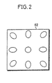
- the image 62 is projected onto the flat projection screen, the image light from the image display apparatus 61 is applied obliquely to end regions of the flat projection screen while it is applied substantially perpendicularly to a central region of the flat projection screen. Therefore, the image 62 projected onto the flat projection screen is more elongated in the opposite end regions than in the central region of the flat projection screen, and hence looks distorted to the game player. Specifically, when an image 62 of nine circular spots is projected onto the flat projection screen, as shown in FIG.
- the central circular spot is displayed as a circular spot on the flat projection screen, but the other circular spots positioned around the central circular spot are displayed as being distorted into elliptical circular spots because the image light of these other circular spots is applied obliquely to the end regions of the flat projection screen.
- the image light emitted from the image display apparatus 61 through a projection lens thereof travels along a light path which is longer in the end regions than in the central region of the flat projection screen. Consequently, the image 62 projected onto the flat projection screen is more enlarged in the end regions than in the central region of the flat projection screen.
- One way of obtaining a three-dimensional and realistic visual perception from images projected in front of the driver's seat is to employ a horizontally long flat projection screen for displaying panoramic images thereon.
- the horizontally long flat projection screen suffers a problem in that the displayed images are greatly elongated or expanded in horizontal end regions of the flat projection screen.
- US-A-5 502 481 discloses a desktop-based stereoscopic projection display system utilizing high-resolution image projectors, keystoning correcting optics and projection beam-folding mirrors which are compactly mounted immediately above the upper volume boundary surface of the overall display volume of the system, in order to permit the use of three-dimensional display structures having footprints and display volumes that are supportable upon desktops and in other viewing environments characterized by spatial restrictions.
- WO 87 / 03980 discloses a comprehensive distortion correction in real time which utilizes fixed transfer characteristics of a projection lens coupled with scene by scene translation of each of a plurality of predetermined points from a projection raster to a location on a view screen.
- Each image is divided into a plurality of spans and the span comers are mapped from the projection raster to the view screen.
- the location of image vertices on the view screen is determined with respect to the viewer and the vertices are mapped to corresponding locations on the projector raster.
- An image is then generated by locating the spans within which each of the vertices is positioned and constructing an image on the projection raster using the map span corners in viewer space and the mapped vertices in projector space.
- the reconstructed predistorted image is then projected onto the view screen so that is appears correct to a viewer.
- JP 08 271979 A discloses a back projection type multi-screen display device which is constituted by using a trapezoid or a polygon having five or more angles.
- an image display apparatus which is capable of projecting natural and realistic images onto a horizontally long projection screen without substantial image distortions such as image elongations or expansions at opposite end regions thereof.
- a computer-readable recording medium which stores a control program for performing such a method.
- an image display apparatus has a concave projection screen extending about an axis and image projecting means for projecting images onto a rear convex surface of the concave projection screen.
- the image display apparatus also has control means for horizontally correcting image data for images to be projected onto respective opposite screen areas of the concave projection screen which are disposed one on each side of the axis.
- a method of projecting images onto a rear convex surface of a concave projection screen extending about an axis comprises the step of horizontally correcting image data for images to be projected onto respective opposite screen areas of the concave projection screen which are disposed one on each side of the axis.
- a computer-readable recording medium storing a control program for projecting images onto a rear convex surface of a concave projection screen extending about an axis.
- the control program comprises the step of horizontally correcting image data for images to be projected onto respective opposite screen areas of the concave projection screen which are disposed one on each side of the axis.
- the image data is horizontally corrected by multiplying the image data by the reciprocal of a horizontal distortion ratio along the concave projection screen.
- Each of the opposite screen areas has a first width
- the horizontal distortion ratio comprises a horizontal elongation ratio of the first width to a width of each of the opposite screen areas as viewed from the image projecting means.
- the concave projection screen has a central screen area disposed between the opposite screen areas, the opposite screen areas being inclined to the central screen area preferably such that the opposite screen areas are progressively away from the image projecting means in directions away from the central screen area.
- the concave projection screen may be divided into a plurality of flat screen areas including the opposite screen areas and the central screen area, and extend around a front side of an observer position.
- the image data is generated as if by respective hypothetical cameras having respective directions of view extending perpendicularly to the flat screen areas, respectively.
- An image display apparatus will be described below as being incorporated in a racing game apparatus which is played by a game player to drive a racing car to compete with other racing cars on road tracks displayed in a virtual three-dimensional game space.
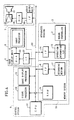
- a racing game apparatus 1 which incorporates the image display apparatus according to the present invention generally comprises an apparatus housing 3 housing a manual controller 2 manually operable by a game player P (see FIG. 6), also referred to as a racing car driver, seated on a driver's seat 27 (see FIG. 6), an image display unit 5 disposed in front of the apparatus housing 3 and having an image projector 4 for projecting a front image, as viewed from the racing car driver, onto a concavely curved projection screen 29 (see FIG.
- control system 6 for executing instructions based on signals entered from the manual controller 2 to generate and supply front image data to the image projector 4, and an audio output unit 7 controlled by the control system 6 for outputting sounds depending on details of images projected from the image projector 4.
- the control system 6 comprises a random-access memory (RAM) 8 for temporarily storing various data, an interface (IF) 9, a signal processor 10, an image display processor 11, and a central processing unit (CPU) 12 for controlling the RAM 8, the interface 9, the signal processor 10, and the image display processor 11.
- the CPU 12, the RAM 8, the interface 9, the signal processor 10, and the image display processor 11 are interconnected by a bus 13 which comprises an address bus, a data bus, and a control bus.
- the manual controller 2 is connected through an interface 14 and an operation information interface 15 to the bus 13. Therefore, signals from the manual controller 2 are delivered through the interfaces 15, 14 and the bus 13 to the CPU 12, which executes instructions based on the signals from the manual controller 2.
- a computer-readable recording medium 17 is connected to the interface 9.
- the RAM 8, the interface 9, and the computer-readable recording medium 17 jointly make up a memory system 16.
- the computer-readable recording medium 17 comprises a read-only memory (ROM) which stores racing game data including image data for generating virtual three-dimensional spatial images, sound data associated with the image data, and control program data including an operating system. Since a racing game is played on the racing game apparatus, the image data for generating virtual three-dimensional spatial images include image data of road tracks and image data of oncoming cars.
- ROM read-only memory
- the signal processor 10 serves to calculate the positions of oncoming cars in two-dimensional coordinates in the virtual three-dimensional graphic environment, generate audio data, process image data of the calculated positions for perspective projection, and horizontally correct the image data for an image to be projected onto the curved projection screen at positions on opposite sides of a central region of the curved projection screen upon the image data processing for perspective projection.
- the image display processor 11 serves to write image data to be displayed into the RAM 8 based on the results of the image data processing carried out by the signal processor 10.
- the CPU 12 controls the signal processor 10 to perform the perspective projection processing including the horizontal image correction, and also controls the image display processor 11 to write image data to be displayed and audio data to be reproduced into the RAM 8 based on the results of the perspective projection processing.
- the audio output unit 7 comprises an interface 18 connected to the bus 13, a digital-to-analog (D/A) converter 19 for converting a digital audio signal from the interface 18 to an analog audio signal, an integrated amplifier 20 for amplifying an analog audio signal from the D/A converter 19, and a speaker 21 for radiating sounds based on an amplified analog audio signal from the integrated amplifier 20.
- Digital audio data written into the RAM 8 by the image display processor 11 is supplied through the bus 13 and the interface 18 to the D/A converter 19, which supplies an analog audio signal through the integrated amplifier 20 to the speaker 21.
- the speaker 21 then radiates sounds depending on how the racing game proceeds.
- the image display unit 5 comprises an interface 22 connected to the bus 13 and a D/A converter 23 for converting a digital image signal from the interface 22 to an analog image signal.
- the image projector 4 projects an image based on an analog image signal from the D/A converter 23, and emits light of the image toward the curved projection screen 29.
- Digital image data written into the RAM 8 by the image display processor 11 is supplied through the bus 13 and the interface 22 to the D/A converter 23, which supplies an analog image signal to the image projector 4.
- the image projector 4 Based on the supplied analog image signal, projects a front image including a road track and competing cars and oncoming cars, as viewed from the racing car driver P seated on the driver's seat 27, onto the curved projection screen 29 at an enlarged scale.
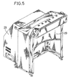
- FIGS. 5 through 7 show a display screen assembly of the racing game apparatus 1.
- the manual controller 2 disposed in the apparatus housing 3 comprises a steering wheel 24, an accelerator pedal 25, and a brake pedal 26.
- the apparatus housing 3 also accommodates the driver's seat 27 for the racing car driver P to be seated.
- the display screen assembly has an outer housing 28 positioned in front of the apparatus housing 2 and housing the image display unit 5, the control system 6, and the audio output unit 7.
- the outer housing 28 also houses the curved projection screen 29 extending around the region in front of the racing car driver seated on the driver's seat 27.
- the outer housing 28 is of a bottomed hollow structure having an inverted L shape with a front opening closed by the curved projection screen 29.
- the image projector 4 is mounted on a bottom plate in the outer housing 28 and has a projection lens (not shown) for emitting the light of a front image, as viewed from the racing car driver, onto the curved projection screen 29.
- the outer housing 28 accommodates therein a reflecting mirror 30 positioned in front of the projection lens and inclined upwardly for reflecting the image light from the image projector 4 obliquely upwardly and a reflecting, mirror 31 positioned in facing relationship to the reflecting mirror 30 for reflecting the image light from the reflecting mirror 30 toward the curved projection screen 29. Therefore, the image light emitted from the image projector 4 is reflected successively by the reflecting mirrors 30, 31 toward a convex rear surface of the curved projection screen 29 at an enlarged scale.
- the CPU 12 detects the clockwise turning movement of the steering wheel 24, controls the signal processor 10 to effect various signal processing depending on the angle through and the speed at which the steering wheel 24 is turned, based on the game data including image data and control program data stored in the recording medium 17, controls the image display processor 11 to write image data to be displayed into the RAM 8 based on the results of the various signal processing effected by the signal processor 10, and controls the image projector 4 to project an image onto the curved projection screen 29 based on the image data supplied from the RAM 8, so that the curved projection screen 29 will display the image of a right-hand area in front of the racing car to make the racing car look as if steered to the right.
- the CPU 12 controls the signal processor 10 and the image display processor 11 to display on the curved projection screen 29 the image of a left-hand area in front of the racing car to make the racing car look as if steered to the left.
- the CPU 12 controls the signal processor 10 and the image display processor 11 to display on the curved projection screen 29 an image as it moves backwards at an increased speed to make the racing car look as if it is accelerated.
- the CPU 12 controls the signal processor 10 and the image display processor 11 to display on the curved projection screen 29 an image as it moves backwards at a reduced speed to make the racing car look as if it is decelerated.
- the curved projection screen 29 is horizontally divided into a plurality of flat screen areas.
- the curved projection screen 29 is horizontally divided into three flat screen areas E1, E2, E3 each having a width W1 and a height L.
- the image light emitted from the image projector 4, which is positioned behind the curved projection screen 29, is projected onto the convex rear surface of the curved projection screen 29, displaying a corresponding image which is viewed by the racing car driver P as if through a front windshield.
- the screen areas E1, E2, E3 of the curved projection screen 29 are spaced at equal distances from the racing car driver P, so that the curved projection screen 29 extends as a horizontally panoramic screen around the curved projection screen 29.
- the racing car driver P can therefore see the displayed image realistically in a wide area in front of the racing car driver P.
- each of the screen areas E1, E2, E3 of the curved projection screen 29 extends flatwise horizontally.
- each of the screen areas E1, E2, E3 of the curved projection screen 29 may be curved horizontally.
- the image projector 4 projects image light at respective angles onto the respective screen areas E1, E2, E3 so that respective images will be displayed on the screen areas E1, E2, E3. Specifically, an image which has not been subjected to any special image processing is projected onto the central screen area E1 at the same width as the width W1 of the central screen area E1.
- the screen areas E2, E3 disposed one on each side of the central screen area E1 are viewed as screen areas E2', E3', respectively, from the image projector 4, each of the screen areas E2', E3' having a width W2 (smaller than the width W1) and a height L.
- the screen areas E2, E3 are inclined to the central screen area E1 such that the screen areas E2, E3 are progressively away from the image projector 4 in directions away from the central screen area E1. Therefore, images which have not been subjected to any special image processing are elongated horizontally when projected from the image projector 4 onto the respective screen areas E2, E3.
- the image data of images to be projected onto the screen areas E2, E3 are multiplied by the reciprocal of a horizontal elongation ratio which is the ratio of the width W1 to the width W2 (W1/W2), thus generating corrected image data with an adjusted aspect ratio and an adjusted angle of view for the screen areas E2', E3'.
- image light based on the corrected image data is emitted from the image projector 4 and projected onto the screen areas E2, E3.
- images represented by the image light for the screen areas E2', E3' are horizontally elongated on the screen areas E2, E3. Since the image data has been multiplied by the reciprocal of the horizontal elongation ratio W1/W2, the images displayed on the screen areas E2, E3 based on the corrected image data are free of horizontal image elongations and look natural.
- inner edges of the screen areas E2, E3 are spaced from the image projector 4 by a smallest distance d1, and outer edges of the screen areas E2, E3 are spaced from the image projector 4 by a largest distance d2.
- the distance d1 remains substantially constant across the width W1 of the central screen area E1. Therefore, images projected onto the respective screen areas E2, E3 based on the image data are expanded at a rate that is greater as the difference between the distances d1, d2 is greater. Because the screen areas E2, E3 are inclined to the central screen area E1, the rate of expansion of the images increases as the distance from the image projector 4 increases from the distance d1 to the distance d2.
- the image data of images to be projected onto the screen areas E2, E3 are multiplied by an image reduction ratio depending on the distance from the image projector 4, thus generating image data for the screen areas E2', E3'. Then, image light based on the corrected image data is emitted from the image projector 4 and projected onto the screen areas E2, E3.
- the image reduction ratio is progressively greater toward the outer edges of the screen areas E2, E3 because the images projected onto the screen areas E2, E3 are more expanded as the distance from the image projector 4 increases.
- the images displayed on the screen areas E2, E3 based on the corrected image data are expanded to their normal size, and hence look natural on the screen areas E2, E3.
- the central screen area E1 is spaced from the image projector 4 by the distance d1 at its outer edges and by a smallest distance d1' at its central region. While the difference between these distances d1, d1' is not significantly large, it is responsible for some image distortions including image elongations and image expansions. Such image distortions will be smaller if the difference between these distances d1, d1' is smaller, i.e., if the width W1 of the central screen area E1 is smaller.
- One way of reducing the width W1 of the central screen area E1 is to divide the curved projection screen into a greater number of screen areas.
- FIGS. 10 and 11 show a curved projection screen 29a which is horizontally divided into five screen areas E11 - E15.
- each of the five screen areas E11 - E15 physically has a width W11.
- the screen areas E12, E14 and E13, E15 disposed on opposite sides of the central screen area W11 are viewed as screen areas E12', E14' and E13', E15', respectively, from the image projector 4.
- the screen areas E12', E14' have respective widths W12, W13 (smaller than the width W11 and the widths W1, W2), and the screen areas E13', E15' have respective widths W12, W13 (smaller than the width W11 and the widths W1, W2).
- the curved projection screen 29a may be horizontally longer than the curved projection screen 29, providing a horizontally longer panoramic view, which is wider and more realistic, in front of the racing car driver.
- the image data of images to be displayed on the respective screen areas E1 - E3 shown in FIGS. 8 and 9 may be generated as if by respective hypothetical cameras which have different directions of view associated respectively with the screen areas E1 - E3. Specifically, these hypothetical cameras may have respective directions of view extending perpendicularly to the respective screen areas E1 - E3.
- Each of the screen areas E1 - E3 as viewed from the racing car driver P subtends an angle of 30° at the racing car driver P. Since the images produced by such hypothetical cameras and displayed on the respective screen areas E1 - E3 are visually perceived as images which are seen by eyes directly facing them simply when the racing car driver P turns his head or eyes toward the screen areas E1 - E3 through 30°, the displayed images look more realistic and three-dimensional.
- the CPU 12 controls the signal processor 10 to process virtual three-dimensional image data for perspective projection and horizontally correct the image data for images to be projected onto the curved projection screen 29, controls the image display processor 11 to write the image data into the RAM 8, and controls the image projector 4 to project images onto the curved projection screen 29 based on the image data read from the RAM 8. Since the image data are horizontally corrected, the images displayed on the curved projection screen 29 are prevented from being horizontally elongated and expanded in the horizontally opposite end regions of the curved projection screen 29. Furthermore, because the curved projection screen 29 gives the racing car driver a horizontally long panoramic view in front of the racing car driver, the images displayed on the curved projection screen 29 look wide and realistic.
- the curved projection screen is horizontally divided into three or five flat screen areas.
- the curved projection screen may be horizontally divided into more than five screen areas which may be either flat or continuously curved. As the number of screen areas increases, the images displayed on these screen areas are more smoothly blended with less noticeable joining lines therebetween. If the number of screen areas is relatively small, then it is necessary to process the image data of images to be projected onto the screen areas in order to make joining lines therebetween less noticeable.
- images based on image data processed for perspective projection and horizontal image correction are projected onto the screen areas E, E2', E3'. If image data is processed for perspective projection and both vertical and horizontal image correction, resultant images are projected onto screen areas as indicated by the dotted lines in FIG. 9.
- control program data and image data may be stored in a computer-readable recording medium such a floppy disk, a CD-ROM, a magnetooptical disk, a DVD-ROM, or the like, and read by a reader in the home game machine or the personal computer into a memory therein.
Description
- The present invention relates to an image display apparatus for use in a game apparatus, such as a racing game apparatus or a shooting game apparatus, or a driving simulation apparatus which will be operated by the player or user while seeing a front three-dimensional graphic image from a driver's seat on a car, a spacecraft, or the like, a method of displaying an image with such an image display apparatus, and a computer-readable recording medium which stores a control program for performing such a method.
- Image display apparatus combined with racing game apparatus, for example, display an image on a display screen as viewed in front of a driver's seat by a car driver seated on the driver's seat behind a steering wheel. The game player operates the racing game apparatus to play the racing game while seeing the displayed image on the display screen. As the racing game played on the racing game apparatus proceeds, the displayed image changes depending on how the game player operates the racing game apparatus. For example, when the game player turns the steering wheel clockwise, the display screen displays the image of a right-hand area in front of the car to make the car look as if steered to the right. Conversely, when the game player turns the steering wheel counterclockwise, the display screen displays the image of a left-hand area in front of the car to make the car look as if steered to the left. When the game player presses the accelerator pedal, the display screen displays an image moving backwards at an increased speed to make the car look as if it is accelerated. When the game player presses the brake pedal, the display screen displays an image moving backwards at a reduced speed to make the car look as if it is decelerated.
- One conventional image display apparatus for use with such a racing game apparatus is shown in FIG. 1 of the accompanying drawings. As shown in FIG. 1, an
image 62 of a road and buildings and trees along the road, as viewed from a driver's seat and changed as the game player operates the racing game apparatus, is projected from animage display apparatus 61 onto a flat projection screen at an enlarged scale for the game player to see with ease. - Since the
image 62 is projected onto the flat projection screen, the image light from theimage display apparatus 61 is applied obliquely to end regions of the flat projection screen while it is applied substantially perpendicularly to a central region of the flat projection screen. Therefore, theimage 62 projected onto the flat projection screen is more elongated in the opposite end regions than in the central region of the flat projection screen, and hence looks distorted to the game player. Specifically, when animage 62 of nine circular spots is projected onto the flat projection screen, as shown in FIG. 2 of the accompanying drawings, the central circular spot is displayed as a circular spot on the flat projection screen, but the other circular spots positioned around the central circular spot are displayed as being distorted into elliptical circular spots because the image light of these other circular spots is applied obliquely to the end regions of the flat projection screen. The image light emitted from theimage display apparatus 61 through a projection lens thereof travels along a light path which is longer in the end regions than in the central region of the flat projection screen. Consequently, theimage 62 projected onto the flat projection screen is more enlarged in the end regions than in the central region of the flat projection screen. - One way of obtaining a three-dimensional and realistic visual perception from images projected in front of the driver's seat is to employ a horizontally long flat projection screen for displaying panoramic images thereon. However, the horizontally long flat projection screen suffers a problem in that the displayed images are greatly elongated or expanded in horizontal end regions of the flat projection screen.
- There is known a data conversion process for converting image data with a virtual spherical screen for three-dimensional spatial image rendering. If the known data conversion process is applied to the projected
image 62 shown in FIG. 3A of the accompanying drawings, then the image data of theimage 62 is converted to image data for displaying a projectedimage 63. However, if the known data conversion process is applied to a projectedimage 62b shown in FIG. 3B of the accompanying drawings, then the image data of the projectedimage 62b is converted to image data for displaying a projectedimage 63b on a flat screen. The projectedimage 63b looks unnatural because its shape is distorted as if viewed through a wide-angle lens. The above data conversion process needs a complex hardware arrangement for its execution because the hardware arrangement should perform a data conversion function for an increased data processing rate. - US-A-5 502 481 discloses a desktop-based stereoscopic projection display system utilizing high-resolution image projectors, keystoning correcting optics and projection beam-folding mirrors which are compactly mounted immediately above the upper volume boundary surface of the overall display volume of the system, in order to permit the use of three-dimensional display structures having footprints and display volumes that are supportable upon desktops and in other viewing environments characterized by spatial restrictions.
- WO 87 / 03980 discloses a comprehensive distortion correction in real time which utilizes fixed transfer characteristics of a projection lens coupled with scene by scene translation of each of a plurality of predetermined points from a projection raster to a location on a view screen. Each image is divided into a plurality of spans and the span comers are mapped from the projection raster to the view screen. The location of image vertices on the view screen is determined with respect to the viewer and the vertices are mapped to corresponding locations on the projector raster. An image is then generated by locating the spans within which each of the vertices is positioned and constructing an image on the projection raster using the map span corners in viewer space and the mapped vertices in projector space. The reconstructed predistorted image is then projected onto the view screen so that is appears correct to a viewer.
- JP 08 271979 A discloses a back projection type multi-screen display device which is constituted by using a trapezoid or a polygon having five or more angles.
- It is the object of the invention to provide an image display apparatus, a method of projecting images and a computer-readable recording medium storing a control program for projecting images which are capable of providing a simple way of projecting natural and realistic images onto a projection screen, in particular when using only a single projector.
- This object is fulfilled by an image display apparatus having the features disclosed in claim 1, a method of projecting images having the features disclosed in
claim 4 and a computer-readable recording medium storing a control program for projecting images having the features disclosed in claim 7. Preferred embodiments are defined in the dependent subclaims. - According to the present invention there is provided an image display apparatus which is capable of projecting natural and realistic images onto a horizontally long projection screen without substantial image distortions such as image elongations or expansions at opposite end regions thereof.
- Furthermore, according to the present invention there is provide a method of displaying an image with such an image display apparatus.
- Further, according to the present invention there is provided a computer-readable recording medium which stores a control program for performing such a method.
- According to an aspect of the present invention, an image display apparatus has a concave projection screen extending about an axis and image projecting means for projecting images onto a rear convex surface of the concave projection screen. The image display apparatus also has control means for horizontally correcting image data for images to be projected onto respective opposite screen areas of the concave projection screen which are disposed one on each side of the axis.
- According to another aspect of the present invention, there is provided a method of projecting images onto a rear convex surface of a concave projection screen extending about an axis. The method comprises the step of horizontally correcting image data for images to be projected onto respective opposite screen areas of the concave projection screen which are disposed one on each side of the axis.
- According to still another aspect of the present invention, there is provided a computer-readable recording medium storing a control program for projecting images onto a rear convex surface of a concave projection screen extending about an axis. The control program comprises the step of horizontally correcting image data for images to be projected onto respective opposite screen areas of the concave projection screen which are disposed one on each side of the axis.
- The image data is horizontally corrected by multiplying the image data by the reciprocal of a horizontal distortion ratio along the concave projection screen.
- Each of the opposite screen areas has a first width, and the horizontal distortion ratio comprises a horizontal elongation ratio of the first width to a width of each of the opposite screen areas as viewed from the image projecting means.
- The concave projection screen has a central screen area disposed between the opposite screen areas, the opposite screen areas being inclined to the central screen area preferably such that the opposite screen areas are progressively away from the image projecting means in directions away from the central screen area.
- The concave projection screen may be divided into a plurality of flat screen areas including the opposite screen areas and the central screen area, and extend around a front side of an observer position. The image data is generated as if by respective hypothetical cameras having respective directions of view extending perpendicularly to the flat screen areas, respectively.
- The above and other objects, features, and advantages of the present invention will become apparent from the following description when taken in conjunction with the accompanying drawings which illustrate preferred embodiments of the present invention by way of example.
-
- FIG. 1 is a plan view of a conventional image display apparatus and a flat screen;
- FIG. 2 is a view of a distorted image projected from the conventional image display apparatus onto the flat screen shown in FIG. 1;
- FIG. 3A is a view showing the manner in which the image data of a projected image is processed by a known data conversion process;
- FIG. 3B is a view showing the manner in which the image data of another projected image is processed by the known data conversion process;
- FIG. 4 is a block diagram of a racing game apparatus according to the present invention;
- FIG. 5 is a perspective view of a display screen assembly of the racing game apparatus shown in FIG. 4;
- FIG. 6 is a vertical cross-sectional view of the display screen assembly shown in FIG. 5;
- FIG. 7 is a horizontal cross-sectional view taken along line VII - VII of FIG. 6;
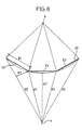
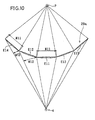
- FIG. 8 is a schematic diagram showing the manner in which an image is projected onto a curved projection screen of the display screen assembly shown in FIG. 5;
- FIG. 9 is a diagram showing three screen areas of the curved projection screen shown in FIG. 8 and those three screen areas as viewed from an image projector;
- FIG. 10 is a schematic diagram showing the manner in which an image is projected onto a curved projection screen having five screen areas; and
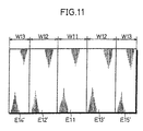
- FIG. 11 is a diagram showing the five screen areas of the curved projection screen illustrated in FIG. 10 as viewed from an image projector.
-
- An image display apparatus according to the present invention will be described below as being incorporated in a racing game apparatus which is played by a game player to drive a racing car to compete with other racing cars on road tracks displayed in a virtual three-dimensional game space.
- As shown in FIG. 4, a racing game apparatus 1 which incorporates the image display apparatus according to the present invention generally comprises an
apparatus housing 3 housing a manual controller 2 manually operable by a game player P (see FIG. 6), also referred to as a racing car driver, seated on a driver's seat 27 (see FIG. 6), an image display unit 5 disposed in front of theapparatus housing 3 and having animage projector 4 for projecting a front image, as viewed from the racing car driver, onto a concavely curved projection screen 29 (see FIG. 5) which extends around a front side of the racing car driver, a control system 6 for executing instructions based on signals entered from the manual controller 2 to generate and supply front image data to theimage projector 4, and an audio output unit 7 controlled by the control system 6 for outputting sounds depending on details of images projected from theimage projector 4. - The control system 6 comprises a random-access memory (RAM) 8 for temporarily storing various data, an interface (IF) 9, a
signal processor 10, animage display processor 11, and a central processing unit (CPU) 12 for controlling theRAM 8, theinterface 9, thesignal processor 10, and theimage display processor 11. TheCPU 12, theRAM 8, theinterface 9, thesignal processor 10, and theimage display processor 11 are interconnected by abus 13 which comprises an address bus, a data bus, and a control bus. The manual controller 2 is connected through aninterface 14 and anoperation information interface 15 to thebus 13. Therefore, signals from the manual controller 2 are delivered through theinterfaces bus 13 to theCPU 12, which executes instructions based on the signals from the manual controller 2. - A computer-
readable recording medium 17 is connected to theinterface 9. TheRAM 8, theinterface 9, and the computer-readable recording medium 17 jointly make up amemory system 16. The computer-readable recording medium 17 comprises a read-only memory (ROM) which stores racing game data including image data for generating virtual three-dimensional spatial images, sound data associated with the image data, and control program data including an operating system. Since a racing game is played on the racing game apparatus, the image data for generating virtual three-dimensional spatial images include image data of road tracks and image data of oncoming cars. - The
signal processor 10 serves to calculate the positions of oncoming cars in two-dimensional coordinates in the virtual three-dimensional graphic environment, generate audio data, process image data of the calculated positions for perspective projection, and horizontally correct the image data for an image to be projected onto the curved projection screen at positions on opposite sides of a central region of the curved projection screen upon the image data processing for perspective projection. - The
image display processor 11 serves to write image data to be displayed into theRAM 8 based on the results of the image data processing carried out by thesignal processor 10. - The
CPU 12 controls thesignal processor 10 to perform the perspective projection processing including the horizontal image correction, and also controls theimage display processor 11 to write image data to be displayed and audio data to be reproduced into theRAM 8 based on the results of the perspective projection processing. - The audio output unit 7 comprises an
interface 18 connected to thebus 13, a digital-to-analog (D/A)converter 19 for converting a digital audio signal from theinterface 18 to an analog audio signal, anintegrated amplifier 20 for amplifying an analog audio signal from the D/A converter 19, and aspeaker 21 for radiating sounds based on an amplified analog audio signal from the integratedamplifier 20. Digital audio data written into theRAM 8 by theimage display processor 11 is supplied through thebus 13 and theinterface 18 to the D/A converter 19, which supplies an analog audio signal through theintegrated amplifier 20 to thespeaker 21. Thespeaker 21 then radiates sounds depending on how the racing game proceeds. - The image display unit 5 comprises an
interface 22 connected to thebus 13 and a D/A converter 23 for converting a digital image signal from theinterface 22 to an analog image signal. Theimage projector 4 projects an image based on an analog image signal from the D/A converter 23, and emits light of the image toward thecurved projection screen 29. Digital image data written into theRAM 8 by theimage display processor 11 is supplied through thebus 13 and theinterface 22 to the D/A converter 23, which supplies an analog image signal to theimage projector 4. Based on the supplied analog image signal, theimage projector 4 projects a front image including a road track and competing cars and oncoming cars, as viewed from the racing car driver P seated on the driver'sseat 27, onto thecurved projection screen 29 at an enlarged scale. - The image display unit 5 and the control system 6, which corrects image data to eliminate image distortions including image elongations and image expansions for projecting inversely distorted images, jointly make up an image display apparatus according to the present invention.
- FIGS. 5 through 7 show a display screen assembly of the racing game apparatus 1.
- As shown in FIG. 6, the manual controller 2 disposed in the
apparatus housing 3 comprises asteering wheel 24, anaccelerator pedal 25, and abrake pedal 26. Theapparatus housing 3 also accommodates the driver'sseat 27 for the racing car driver P to be seated. As shown in FIGS. 5 through 7, the display screen assembly has anouter housing 28 positioned in front of the apparatus housing 2 and housing the image display unit 5, the control system 6, and the audio output unit 7. Theouter housing 28 also houses thecurved projection screen 29 extending around the region in front of the racing car driver seated on the driver'sseat 27. Theouter housing 28 is of a bottomed hollow structure having an inverted L shape with a front opening closed by thecurved projection screen 29. - As shown in FIGS. 6 and 7, the
image projector 4 is mounted on a bottom plate in theouter housing 28 and has a projection lens (not shown) for emitting the light of a front image, as viewed from the racing car driver, onto thecurved projection screen 29. Theouter housing 28 accommodates therein a reflectingmirror 30 positioned in front of the projection lens and inclined upwardly for reflecting the image light from theimage projector 4 obliquely upwardly and a reflecting,mirror 31 positioned in facing relationship to the reflectingmirror 30 for reflecting the image light from the reflectingmirror 30 toward thecurved projection screen 29. Therefore, the image light emitted from theimage projector 4 is reflected successively by the reflecting mirrors 30, 31 toward a convex rear surface of thecurved projection screen 29 at an enlarged scale. - When the racing car driver P turns the
steering wheel 24 clockwise, theCPU 12 detects the clockwise turning movement of thesteering wheel 24, controls thesignal processor 10 to effect various signal processing depending on the angle through and the speed at which thesteering wheel 24 is turned, based on the game data including image data and control program data stored in therecording medium 17, controls theimage display processor 11 to write image data to be displayed into theRAM 8 based on the results of the various signal processing effected by thesignal processor 10, and controls theimage projector 4 to project an image onto thecurved projection screen 29 based on the image data supplied from theRAM 8, so that thecurved projection screen 29 will display the image of a right-hand area in front of the racing car to make the racing car look as if steered to the right. Conversely, when the racing car driver P turns thesteering wheel 24 counterclockwise, theCPU 12 controls thesignal processor 10 and theimage display processor 11 to display on thecurved projection screen 29 the image of a left-hand area in front of the racing car to make the racing car look as if steered to the left. When the racing car driver P presses theaccelerator pedal 25, theCPU 12 controls thesignal processor 10 and theimage display processor 11 to display on thecurved projection screen 29 an image as it moves backwards at an increased speed to make the racing car look as if it is accelerated. When the game player presses the brake pedal, theCPU 12 controls thesignal processor 10 and theimage display processor 11 to display on thecurved projection screen 29 an image as it moves backwards at a reduced speed to make the racing car look as if it is decelerated. - Horizontal correction of image data for the shape and size of a front image projected onto and displayed on the
curved projection screen 29 will be described below with reference to FIGS. 8 through 11. - The
curved projection screen 29 is horizontally divided into a plurality of flat screen areas. For example, as shown in FIGS. 8 and 9, thecurved projection screen 29 is horizontally divided into three flat screen areas E1, E2, E3 each having a width W1 and a height L. The image light emitted from theimage projector 4, which is positioned behind thecurved projection screen 29, is projected onto the convex rear surface of thecurved projection screen 29, displaying a corresponding image which is viewed by the racing car driver P as if through a front windshield. As shown in FIG. 8, the screen areas E1, E2, E3 of thecurved projection screen 29 are spaced at equal distances from the racing car driver P, so that thecurved projection screen 29 extends as a horizontally panoramic screen around thecurved projection screen 29. The racing car driver P can therefore see the displayed image realistically in a wide area in front of the racing car driver P. - In FIGS. 8 and 9, each of the screen areas E1, E2, E3 of the
curved projection screen 29 extends flatwise horizontally. However, each of the screen areas E1, E2, E3 of thecurved projection screen 29 may be curved horizontally. - The
image projector 4 projects image light at respective angles onto the respective screen areas E1, E2, E3 so that respective images will be displayed on the screen areas E1, E2, E3. Specifically, an image which has not been subjected to any special image processing is projected onto the central screen area E1 at the same width as the width W1 of the central screen area E1. The screen areas E2, E3 disposed one on each side of the central screen area E1 are viewed as screen areas E2', E3', respectively, from theimage projector 4, each of the screen areas E2', E3' having a width W2 (smaller than the width W1) and a height L. The screen areas E2, E3 are inclined to the central screen area E1 such that the screen areas E2, E3 are progressively away from theimage projector 4 in directions away from the central screen area E1. Therefore, images which have not been subjected to any special image processing are elongated horizontally when projected from theimage projector 4 onto the respective screen areas E2, E3. To project unelongated images onto the screen areas E2, E3, the image data of images to be projected onto the screen areas E2, E3 are multiplied by the reciprocal of a horizontal elongation ratio which is the ratio of the width W1 to the width W2 (W1/W2), thus generating corrected image data with an adjusted aspect ratio and an adjusted angle of view for the screen areas E2', E3'. Then, image light based on the corrected image data is emitted from theimage projector 4 and projected onto the screen areas E2, E3. When the image light is actually projected onto the screen areas E2, E3, images represented by the image light for the screen areas E2', E3' are horizontally elongated on the screen areas E2, E3. Since the image data has been multiplied by the reciprocal of the horizontal elongation ratio W1/W2, the images displayed on the screen areas E2, E3 based on the corrected image data are free of horizontal image elongations and look natural. - Furthermore, as shown in FIG. 8, inner edges of the screen areas E2, E3 are spaced from the
image projector 4 by a smallest distance d1, and outer edges of the screen areas E2, E3 are spaced from theimage projector 4 by a largest distance d2. The distance d1 remains substantially constant across the width W1 of the central screen area E1. Therefore, images projected onto the respective screen areas E2, E3 based on the image data are expanded at a rate that is greater as the difference between the distances d1, d2 is greater. Because the screen areas E2, E3 are inclined to the central screen area E1, the rate of expansion of the images increases as the distance from theimage projector 4 increases from the distance d1 to the distance d2. To project unexpanded images onto the screen areas E2, E3, the image data of images to be projected onto the screen areas E2, E3 are multiplied by an image reduction ratio depending on the distance from theimage projector 4, thus generating image data for the screen areas E2', E3'. Then, image light based on the corrected image data is emitted from theimage projector 4 and projected onto the screen areas E2, E3. The image reduction ratio is progressively greater toward the outer edges of the screen areas E2, E3 because the images projected onto the screen areas E2, E3 are more expanded as the distance from theimage projector 4 increases. Since the image data has been reduced at the image reduction ratio that is greater toward the outer edges of the screen areas E2, E3, the images displayed on the screen areas E2, E3 based on the corrected image data are expanded to their normal size, and hence look natural on the screen areas E2, E3. - The central screen area E1 is spaced from the
image projector 4 by the distance d1 at its outer edges and by a smallest distance d1' at its central region. While the difference between these distances d1, d1' is not significantly large, it is responsible for some image distortions including image elongations and image expansions. Such image distortions will be smaller if the difference between these distances d1, d1' is smaller, i.e., if the width W1 of the central screen area E1 is smaller. One way of reducing the width W1 of the central screen area E1 is to divide the curved projection screen into a greater number of screen areas. - FIGS. 10 and 11 show a
curved projection screen 29a which is horizontally divided into five screen areas E11 - E15. As shown in FIG. 10, each of the five screen areas E11 - E15 physically has a width W11. The screen areas E12, E14 and E13, E15 disposed on opposite sides of the central screen area W11 are viewed as screen areas E12', E14' and E13', E15', respectively, from theimage projector 4. The screen areas E12', E14' have respective widths W12, W13 (smaller than the width W11 and the widths W1, W2), and the screen areas E13', E15' have respective widths W12, W13 (smaller than the width W11 and the widths W1, W2). Since these screen areas E11 - E15 are narrower than the screen areas E1 - E3 shown in FIGS. 8 and 9, projected images displayed on the screen areas E11 - E15 suffer less image distortions than the images displayed on the screen areas E1 - E3. In addition, if the widths W11 - W13 are suitably selected, thecurved projection screen 29a may be horizontally longer than thecurved projection screen 29, providing a horizontally longer panoramic view, which is wider and more realistic, in front of the racing car driver. - The image data of images to be displayed on the respective screen areas E1 - E3 shown in FIGS. 8 and 9 may be generated as if by respective hypothetical cameras which have different directions of view associated respectively with the screen areas E1 - E3. Specifically, these hypothetical cameras may have respective directions of view extending perpendicularly to the respective screen areas E1 - E3. Each of the screen areas E1 - E3 as viewed from the racing car driver P subtends an angle of 30° at the racing car driver P. Since the images produced by such hypothetical cameras and displayed on the respective screen areas E1 - E3 are visually perceived as images which are seen by eyes directly facing them simply when the racing car driver P turns his head or eyes toward the screen areas E1 - E3 through 30°, the displayed images look more realistic and three-dimensional.
- Based on the control program data stored in the computer-
readable recording medium 17, theCPU 12 controls thesignal processor 10 to process virtual three-dimensional image data for perspective projection and horizontally correct the image data for images to be projected onto thecurved projection screen 29, controls theimage display processor 11 to write the image data into theRAM 8, and controls theimage projector 4 to project images onto thecurved projection screen 29 based on the image data read from theRAM 8. Since the image data are horizontally corrected, the images displayed on thecurved projection screen 29 are prevented from being horizontally elongated and expanded in the horizontally opposite end regions of thecurved projection screen 29. Furthermore, because thecurved projection screen 29 gives the racing car driver a horizontally long panoramic view in front of the racing car driver, the images displayed on thecurved projection screen 29 look wide and realistic. - In the illustrated embodiments, the curved projection screen is horizontally divided into three or five flat screen areas. However, the curved projection screen may be horizontally divided into more than five screen areas which may be either flat or continuously curved. As the number of screen areas increases, the images displayed on these screen areas are more smoothly blended with less noticeable joining lines therebetween. If the number of screen areas is relatively small, then it is necessary to process the image data of images to be projected onto the screen areas in order to make joining lines therebetween less noticeable.
- In the embodiment shown in FIGS. 8 and 9, images based on image data processed for perspective projection and horizontal image correction are projected onto the screen areas E, E2', E3'. If image data is processed for perspective projection and both vertical and horizontal image correction, resultant images are projected onto screen areas as indicated by the dotted lines in FIG. 9.
- The image display apparatus according to the present invention has been described above in combination with the racing game apparatus. However, the image display apparatus according to the present invention may be used in other game machines or driving simulation apparatus as arcade game machines. If the image display apparatus is used a home game machine or a personal computer, then control program data and image data may be stored in a computer-readable recording medium such a floppy disk, a CD-ROM, a magnetooptical disk, a DVD-ROM, or the like, and read by a reader in the home game machine or the personal computer into a memory therein.
- Although certain preferred embodiments of the present invention have been shown and described in detail, it should be understood that various changes and modifications may be made therein without departing from the scope of the appended claims.
Claims (9)
- An image display apparatus (5, 6) comprising:characterized in that said control means (10) comprises means for multiplying said image data by the reciprocal of a horizontal elongation ratio along said concave projection screen (29; 29a) to correct shape and size of the image data, said horizontal elongation ratio being the ratio of said first width (W1; W11) of each of said opposite screen areas (E2, E3; E12, E13, E14, E15) to a width (W2; W12, W13) of each of said opposite screen areas (E2, E3; E12, E13, E14, E15) as viewed from said image projecting means (4).a concave projection screen (29; 29a) extending about an axis, the projection screen (29; 29a) comprising a central screen area (E1) and opposite screen areas (E2, E3; E12, E13, E14, E15) being disposed at opposite sides of said central screen area (E1), the opposite screen areas (E2, E3; E12, E13, E14, E15) being inclined with respect to central screen area (E1) and having parallel vertical sides, wherein each of said opposite screen areas (E2, E3; E12, E13, E14, E15) has a first width (W1; W11) being the physical width of said opposite screen areas (E2, E3; E12, E13, E14, E15);image projecting means (4) for projecting images onto a rear convex surface of said concave projection screen (29; 29a); andcontrol means (10) for horizontally correcting image data for images to be projected onto said opposite screen areas (E2, E3; E12, E13, E14, E15) of said concave projection screen (29; 29a),
- An image display apparatus (5, 6) according to claim 1, characterized in that said opposite screen areas (E2, E3; E12, E13, E14, E15) are inclined to said central screen area (E1; E11) such that said opposite screen areas (E2, E3; E12, E13, E14, E15) are progressively away from said image projecting means (4) in directions away from said central screen area (E1; E11).
- An image display apparatus (5, 6) according to claim 1, characterized in that said concave projection screen (29; 29a) is divided into a plurality of flat screen areas (E1, E2, E3; E11, E12, E13, E14, E15) including said opposite screen areas (E2, E3; E12, E13, E14, E15) and said central screen area (E1; E11), said concave projection screen (29; 29a) extending around a front side of an observer position, said image data being generated as if by respective hypothetical cameras having respective directions of view extending perpendicularly to said flat screen areas (E1, E2, E3; E11, E12, E13, E14, E15), respectively.
- A method of projecting images onto a rear convex surface of a concave projection screen (29; 29a) extending about an axis, the projection screen (29; 29a) comprising a central screen area (E1) and opposite screen areas (E2, E3; E12, E13, E14, E15) being disposed at opposite sides of said central screen area (E1), the opposite screen areas (E2, E3; E12, E13, E14, E15) being inclined with respect to each other and having parallel vertical sides, wherein each of said opposite screen areas (E2, E3; E12, E13, E14, E15) has a first width (W1; W11) being the physical width of said opposite screen areas (E2, E3; E12, E13, E14, E15), comprising the step of:characterized in that said step of horizontally correcting image data comprises the step of multiplying said image data by the reciprocal of a horizontal elongation ratio along said concave projection screen (29; 29a) to correct shape and size of the image data, said horizontal elongation ratio being the ratio of said first width (W1; W11) to a width (W2; W12, W13) of each of said opposite screen areas (E2, E3; E12, E13, E14, E15) as viewed from said image projecting means (4).horizontally correcting image data for images to be projected onto said opposite screen areas (E2, E3; E12, E13, E14, E15) of said concave projection screen (29; 29a),
- A method according to claim 4, characterized in that said opposite screen areas (E2, E3; E12, E13, E14, E15) are inclined to said central screen area (E1; E11) such that said opposite screen areas (E2, E3; E12, E13, E14, E15) are progressively away from said image projecting means (4) in directions away from said central screen area (E1; E11).
- A method according to claim 4, characterized in that said concave projection screen (29; 29a) is divided into a plurality of flat screen areas (E1, E2, E3; E11, E12, E13, E14, E15) including said opposite screen areas (E2, E3; E12, E13, E14, E15) and said central screen area (E1; E11), said concave projection screen (29; 29a) extending around a front side of an observer position, said image data being generated as if by respective hypothetical cameras having respective directions of view extending perpendicularly to said flat screen areas (E1, E2, E3; E11, E12, E13, E14, E15), respectively.
- A computer-readable recording mediurn storing a control program for projecting images onto a rear convex surface of a concave projection screen (29; 29a) extending about an axis, the projection screen (29; 29a) comprising a central screen area (E1) and opposite screen areas (E2, E3; E12, E13, E14, E15) being disposed at opposite sides of said central screen area (E1), the opposite screen areas (E2, E3; E12, E13, E14, E15) being inclined with respect to each other and having parallel vertical sides, wherein each of said opposite screen areas (E2, E3; E12, E13, E14, E15) has a first width (W1; W11) being the physical width of said opposite screen areas (E2, E3; E12, E13, E14, E15), said control program comprising the step of:characterized in that said step of horizontally correcting image data comprises the step of multiplying said image data by the reciprocal of a horizontal elongation ratio along said concave projection screen (29; 29a) to correct shape and size of image data, said horizontal elongation ratio being the ratio of said first width (W1; W11) to a width of each of said opposite screen areas (E2, E3; E12, E13, E14, E15) as viewed from said image projecting means (4).horizontally correcting image data for images to be projected onto said opposite-screen areas of said concave projection screen (29; 29a),
- A computer-readable recording medium according to claim 7, characterized in that said opposite screen areas (E2, E3; E12, E13, E14, E15) are inclined to said central screen area (E1; E11) such that said opposite screen areas (E2, E3; E12, E13, E14, E15) are progressively away from said image projecting means (4) in directions away from said central screen area (E1; E11).
- A computer-readable recording medium according to claim 7, characterized in that said concave projection screen (29; 29a) is divided into a plurality of flat screen areas (E1, E2, E3; E11, E12, E13, E14, E15) including said opposite screen areas (E2, E3; E12, E13, E14, E15) and said central screen area (E1; E11), said concave projection screen (29; 29a) extending around a front side of an observer position, said image data being generated as if by respective hypothetical cameras having respective directions of view extending perpendicularly to said flat screen areas (E1, E2, E3; E11, E12, E13, E14, E15), respectively.
Applications Claiming Priority (3)
| Application Number | Priority Date | Filing Date | Title |
|---|---|---|---|
| JP09251667A JP3079073B2 (en) | 1997-09-17 | 1997-09-17 | Image display device, image display method, and readable recording medium |
| JP25166797 | 1997-09-17 | ||
| JP251667/97 | 1997-09-17 |
Publications (3)
| Publication Number | Publication Date |
|---|---|
| EP0903696A2 EP0903696A2 (en) | 1999-03-24 |
| EP0903696A3 EP0903696A3 (en) | 1999-04-14 |
| EP0903696B1 true EP0903696B1 (en) | 2002-11-27 |
Family
ID=17226238
Family Applications (1)
| Application Number | Title | Priority Date | Filing Date |
|---|---|---|---|
| EP98117684A Expired - Lifetime EP0903696B1 (en) | 1997-09-17 | 1998-09-17 | Apparatus for and method of displaying image and computer-readable recording medium |
Country Status (9)
| Country | Link |
|---|---|
| US (1) | US6297814B1 (en) |
| EP (1) | EP0903696B1 (en) |
| JP (1) | JP3079073B2 (en) |
| KR (1) | KR100318865B1 (en) |
| CN (1) | CN1116658C (en) |
| AU (1) | AU726228B2 (en) |
| DE (1) | DE69809670T2 (en) |
| HK (1) | HK1017466A1 (en) |
| TW (1) | TW371268B (en) |
Families Citing this family (28)
| Publication number | Priority date | Publication date | Assignee | Title |
|---|---|---|---|---|
| US6819333B1 (en) * | 2000-05-12 | 2004-11-16 | Silicon Graphics, Inc. | System and method for displaying an image using display distortion correction |
| GB0014672D0 (en) * | 2000-06-15 | 2000-08-09 | Seos Displays Ltd | Improved visual display apparatus |
| US6578971B1 (en) * | 2002-02-12 | 2003-06-17 | Conocophillips Company | Self-illuminating concave video screen system |
| WO2003069406A1 (en) * | 2002-02-12 | 2003-08-21 | Conocophillips Company | Self-illuminating concave video screen system |
| US6623120B2 (en) * | 2002-02-12 | 2003-09-23 | Conocophillips Company | Video projection system and design method therefor |
| JP2005049913A (en) * | 2003-05-30 | 2005-02-24 | Konami Computer Entertainment Yokyo Inc | Image processor, image processing method, and program |
| CN100341029C (en) * | 2004-07-02 | 2007-10-03 | 四川华控图形科技有限公司 | Correcting method for curve projection geometry of artificial site |
| US20070126864A1 (en) * | 2005-12-05 | 2007-06-07 | Kiran Bhat | Synthesizing three-dimensional surround visual field |
| US20070141545A1 (en) * | 2005-12-05 | 2007-06-21 | Kar-Han Tan | Content-Based Indexing and Retrieval Methods for Surround Video Synthesis |
| US20070126932A1 (en) * | 2005-12-05 | 2007-06-07 | Kiran Bhat | Systems and methods for utilizing idle display area |
| US8130330B2 (en) * | 2005-12-05 | 2012-03-06 | Seiko Epson Corporation | Immersive surround visual fields |
| US20070174010A1 (en) * | 2006-01-24 | 2007-07-26 | Kiran Bhat | Collective Behavior Modeling for Content Synthesis |
| CA2653125C (en) | 2006-06-08 | 2012-04-24 | Panasonic Electric Works Co., Ltd. | Image display device |
| US20080018792A1 (en) * | 2006-07-19 | 2008-01-24 | Kiran Bhat | Systems and Methods for Interactive Surround Visual Field |
| US8224122B2 (en) * | 2006-12-15 | 2012-07-17 | Microsoft Corporation | Dynamic viewing of wide angle images |
| US8117541B2 (en) | 2007-03-06 | 2012-02-14 | Wildtangent, Inc. | Rendering of two-dimensional markup messages |
| JP4732391B2 (en) * | 2007-03-26 | 2011-07-27 | 三菱電機株式会社 | Projection display |
| JP4714231B2 (en) * | 2008-03-28 | 2011-06-29 | 株式会社コナミデジタルエンタテインメント | Image generating apparatus, wide-field image generating method, and program |
| US20100022354A1 (en) * | 2008-07-25 | 2010-01-28 | Expresso Fitness Corp. | Exercise equipment with movable handle bars to simulate steering motion in a simulated environment and methods therefor |
| US8092287B2 (en) * | 2008-12-04 | 2012-01-10 | Disney Enterprises, Inc. | System and method for providing a real-time interactive surface |
| CN102789513B (en) * | 2011-12-29 | 2015-06-03 | 北京睿联嘉业投资管理有限公司 | Multi-space simulator framework provided with active window structure |
| JP2013167732A (en) * | 2012-02-15 | 2013-08-29 | Japan Radio Co Ltd | Display, screen and image conversion apparatus |
| JP6155764B2 (en) * | 2013-03-29 | 2017-07-05 | 株式会社コナミデジタルエンタテインメント | game machine |
| JP2016067570A (en) * | 2014-09-29 | 2016-05-09 | 株式会社セガゲームス | Game apparatus and image display device |
| KR102223792B1 (en) * | 2014-11-10 | 2021-03-04 | 엘지디스플레이 주식회사 | Apparatus and method for correcting image distortion, curved display device including the same |
| KR102547943B1 (en) * | 2018-01-05 | 2023-06-26 | 삼성디스플레이 주식회사 | Head-mounted display device |
| CN112995620B (en) * | 2019-12-17 | 2024-01-02 | 青岛海高设计制造有限公司 | Method for correcting cylindrical projection, device for cylindrical projection and household appliance |
| CN115282591A (en) * | 2020-02-10 | 2022-11-04 | 首望体验科技文化有限公司 | Panoramic immersive game system for 720 panoramic cinema and 720 panoramic cinema |
Family Cites Families (8)
| Publication number | Priority date | Publication date | Assignee | Title |
|---|---|---|---|---|
| US4656506A (en) * | 1983-02-25 | 1987-04-07 | Ritchey Kurtis J | Spherical projection system |
| EP0250588B1 (en) | 1985-12-19 | 1991-10-16 | General Electric Company | Comprehensive distortion correction in a real time imaging system |
| GB2185360B (en) * | 1986-01-11 | 1989-10-25 | Pilkington Perkin Elmer Ltd | Display system |
| US5502481A (en) | 1992-11-16 | 1996-03-26 | Reveo, Inc. | Desktop-based projection display system for stereoscopic viewing of displayed imagery over a wide field of view |
| US5695406A (en) * | 1994-05-04 | 1997-12-09 | Park; Brian V. | Immersive cyberspace system |
| JPH08271979A (en) | 1995-01-30 | 1996-10-18 | Hitachi Ltd | Back projection type multi-screen display device and display system using it |
| JPH10171016A (en) * | 1996-10-09 | 1998-06-26 | Sanyo Electric Co Ltd | Rear surface projection type display device |
| US5864431A (en) * | 1997-07-07 | 1999-01-26 | Redifun Stimulation, Inc. | Method and apparatus for elimination of distortion in rear projection to curved surfaces |
-
1997
- 1997-09-17 JP JP09251667A patent/JP3079073B2/en not_active Expired - Lifetime
-
1998
- 1998-09-09 US US09/149,667 patent/US6297814B1/en not_active Expired - Lifetime
- 1998-09-10 TW TW087115099A patent/TW371268B/en not_active IP Right Cessation
- 1998-09-11 KR KR1019980037544A patent/KR100318865B1/en not_active IP Right Cessation
- 1998-09-15 CN CN98119189A patent/CN1116658C/en not_active Expired - Fee Related
- 1998-09-16 AU AU85196/98A patent/AU726228B2/en not_active Ceased
- 1998-09-17 DE DE69809670T patent/DE69809670T2/en not_active Expired - Lifetime
- 1998-09-17 EP EP98117684A patent/EP0903696B1/en not_active Expired - Lifetime
-
1999
- 1999-06-21 HK HK99102630A patent/HK1017466A1/en not_active IP Right Cessation
Also Published As
| Publication number | Publication date |
|---|---|
| HK1017466A1 (en) | 1999-11-19 |
| KR19990029733A (en) | 1999-04-26 |
| DE69809670D1 (en) | 2003-01-09 |
| CN1213809A (en) | 1999-04-14 |
| US6297814B1 (en) | 2001-10-02 |
| EP0903696A3 (en) | 1999-04-14 |
| CN1116658C (en) | 2003-07-30 |
| AU8519698A (en) | 1999-04-01 |
| JPH1190041A (en) | 1999-04-06 |
| EP0903696A2 (en) | 1999-03-24 |
| TW371268B (en) | 1999-10-01 |
| AU726228B2 (en) | 2000-11-02 |
| KR100318865B1 (en) | 2002-04-22 |
| DE69809670T2 (en) | 2003-07-17 |
| JP3079073B2 (en) | 2000-08-21 |
Similar Documents
| Publication | Publication Date | Title |
|---|---|---|
| EP0903696B1 (en) | Apparatus for and method of displaying image and computer-readable recording medium | |
| US5577960A (en) | Image synthesizing system and game playing apparatus using the same | |
| US5919045A (en) | Interactive race car simulator system | |
| US6377277B1 (en) | Virtual image generation apparatus and method | |
| US6354838B1 (en) | Interactive race car simulator system | |
| EP0841640A1 (en) | An image processor, a game machine using the image processor, a method of image processing and a medium | |
| WO2015122450A1 (en) | Image generation system, image generation method, and information storage medium | |
| JPWO2004045734A1 (en) | Game image processing program and storage medium | |
| US5181122A (en) | Display device for displaying a wide picture | |
| JP2013211672A (en) | Curved surface projection stereoscopic vision device | |
| JP2001184040A (en) | Image data display system and image data creation method | |
| JP3955425B2 (en) | 3D sound reproduction system | |
| GB2284526A (en) | Image synthesizer and apparatus for playing game using the image synthesizer | |
| JPH06327090A (en) | Theater device, audio equipment and amusement device | |
| JP4303395B2 (en) | GAME DEVICE AND INFORMATION STORAGE MEDIUM | |
| JP2714647B2 (en) | Image-linked audio playback method | |
| JP2002304640A (en) | Method and device for three-dimensional image processing, three-dimensional image processing program, and video game device | |
| JP3179320B2 (en) | Three-dimensional game device and image composition method | |
| JPH0836355A (en) | Pseudo three-dimensional image forming method and device therefor | |
| JPH09147143A (en) | Device and method for image composition | |
| JP2007323001A (en) | Image display device | |
| JP2020162089A (en) | Image generation device and image generation method | |
| JP2001314648A (en) | Game apparatus and information storage medium | |
| JP3452512B2 (en) | GAME DEVICE AND GAME IMAGE GENERATION METHOD | |
| JPH0728388A (en) | Drive simulator for vehicle |
Legal Events
| Date | Code | Title | Description |
|---|---|---|---|
| PUAI | Public reference made under article 153(3) epc to a published international application that has entered the european phase |
Free format text: ORIGINAL CODE: 0009012 |
|
| PUAL | Search report despatched |
Free format text: ORIGINAL CODE: 0009013 |
|
| AK | Designated contracting states |
Kind code of ref document: A2 Designated state(s): DE FR GB IT |
|
| AX | Request for extension of the european patent |
Free format text: AL;LT;LV;MK;RO;SI |
|
| AK | Designated contracting states |
Kind code of ref document: A3 Designated state(s): AT BE CH CY DE DK ES FI FR GB GR IE IT LI LU MC NL PT SE |
|
| AX | Request for extension of the european patent |
Free format text: AL;LT;LV;MK;RO;SI |
|
| 17P | Request for examination filed |
Effective date: 19990902 |
|
| AKX | Designation fees paid |
Free format text: DE FR GB IT |
|
| 17Q | First examination report despatched |
Effective date: 20001213 |
|
| GRAG | Despatch of communication of intention to grant |
Free format text: ORIGINAL CODE: EPIDOS AGRA |
|
| GRAG | Despatch of communication of intention to grant |
Free format text: ORIGINAL CODE: EPIDOS AGRA |
|
| GRAH | Despatch of communication of intention to grant a patent |
Free format text: ORIGINAL CODE: EPIDOS IGRA |
|
| GRAH | Despatch of communication of intention to grant a patent |
Free format text: ORIGINAL CODE: EPIDOS IGRA |
|
| GRAA | (expected) grant |
Free format text: ORIGINAL CODE: 0009210 |
|
| AK | Designated contracting states |
Kind code of ref document: B1 Designated state(s): DE FR GB IT |
|
| REG | Reference to a national code |
Ref country code: GB Ref legal event code: FG4D |
|
| REF | Corresponds to: |
Ref document number: 69809670 Country of ref document: DE Date of ref document: 20030109 |
|
| ET | Fr: translation filed | ||
| PLBE | No opposition filed within time limit |
Free format text: ORIGINAL CODE: 0009261 |
|
| STAA | Information on the status of an ep patent application or granted ep patent |
Free format text: STATUS: NO OPPOSITION FILED WITHIN TIME LIMIT |
|
| 26N | No opposition filed |
Effective date: 20030828 |
|
| REG | Reference to a national code |
Ref country code: GB Ref legal event code: 732E Free format text: REGISTERED BETWEEN 20090514 AND 20090520 |
|
| REG | Reference to a national code |
Ref country code: FR Ref legal event code: TP Ref country code: FR Ref legal event code: CD Ref country code: FR Ref legal event code: CA |
|
| PGFP | Annual fee paid to national office [announced via postgrant information from national office to epo] |
Ref country code: GB Payment date: 20120920 Year of fee payment: 15 |
|
| PGFP | Annual fee paid to national office [announced via postgrant information from national office to epo] |
Ref country code: DE Payment date: 20120921 Year of fee payment: 15 |
|
| PGFP | Annual fee paid to national office [announced via postgrant information from national office to epo] |
Ref country code: FR Payment date: 20121010 Year of fee payment: 15 |
|
| PGFP | Annual fee paid to national office [announced via postgrant information from national office to epo] |
Ref country code: IT Payment date: 20120928 Year of fee payment: 15 |
|
| GBPC | Gb: european patent ceased through non-payment of renewal fee |
Effective date: 20130917 |
|
| REG | Reference to a national code |
Ref country code: DE Ref legal event code: R119 Ref document number: 69809670 Country of ref document: DE Effective date: 20140401 |
|
| REG | Reference to a national code |
Ref country code: FR Ref legal event code: ST Effective date: 20140530 |
|
| PG25 | Lapsed in a contracting state [announced via postgrant information from national office to epo] |
Ref country code: GB Free format text: LAPSE BECAUSE OF NON-PAYMENT OF DUE FEES Effective date: 20130917 |
|
| PG25 | Lapsed in a contracting state [announced via postgrant information from national office to epo] |
Ref country code: IT Free format text: LAPSE BECAUSE OF NON-PAYMENT OF DUE FEES Effective date: 20130917 Ref country code: FR Free format text: LAPSE BECAUSE OF NON-PAYMENT OF DUE FEES Effective date: 20130930 Ref country code: DE Free format text: LAPSE BECAUSE OF NON-PAYMENT OF DUE FEES Effective date: 20140401 |