EP0903464A2 - Well fluid sampling apparatus - Google Patents
Well fluid sampling apparatus Download PDFInfo
- Publication number
- EP0903464A2 EP0903464A2 EP98307551A EP98307551A EP0903464A2 EP 0903464 A2 EP0903464 A2 EP 0903464A2 EP 98307551 A EP98307551 A EP 98307551A EP 98307551 A EP98307551 A EP 98307551A EP 0903464 A2 EP0903464 A2 EP 0903464A2
- Authority
- EP
- European Patent Office
- Prior art keywords
- chamber
- fluid
- sampling
- piston
- sampling port
- Prior art date
- Legal status (The legal status is an assumption and is not a legal conclusion. Google has not performed a legal analysis and makes no representation as to the accuracy of the status listed.)
- Withdrawn
Links
Images


Classifications
-
- E—FIXED CONSTRUCTIONS
- E21—EARTH OR ROCK DRILLING; MINING
- E21B—EARTH OR ROCK DRILLING; OBTAINING OIL, GAS, WATER, SOLUBLE OR MELTABLE MATERIALS OR A SLURRY OF MINERALS FROM WELLS
- E21B49/00—Testing the nature of borehole walls; Formation testing; Methods or apparatus for obtaining samples of soil or well fluids, specially adapted to earth drilling or wells
- E21B49/08—Obtaining fluid samples or testing fluids, in boreholes or wells
- E21B49/081—Obtaining fluid samples or testing fluids, in boreholes or wells with down-hole means for trapping a fluid sample
- E21B49/0813—Sampling valve actuated by annulus pressure changes
-
- E—FIXED CONSTRUCTIONS
- E21—EARTH OR ROCK DRILLING; MINING
- E21B—EARTH OR ROCK DRILLING; OBTAINING OIL, GAS, WATER, SOLUBLE OR MELTABLE MATERIALS OR A SLURRY OF MINERALS FROM WELLS
- E21B49/00—Testing the nature of borehole walls; Formation testing; Methods or apparatus for obtaining samples of soil or well fluids, specially adapted to earth drilling or wells
- E21B49/08—Obtaining fluid samples or testing fluids, in boreholes or wells
- E21B49/081—Obtaining fluid samples or testing fluids, in boreholes or wells with down-hole means for trapping a fluid sample
- E21B49/0815—Sampling valve actuated by tubing pressure changes
Definitions
- This invention relates generally to fluid sampling apparatus.
- a fluid sampling tool and method of use which, in response to pressure, opens to collect a fluid sample, and more particularly, to a sampling tool which provides for collection of a fluid sample without flashing of vapor in the liquid and which retains the fluid in a supercharged condition.
- the invention particularly relates to a non-flashing fluid sampler and method.
- a fluid sampling tool is first lowered into the well on a tubing string or a wireline or a slick line.
- a port one or more openings defined in the tool is opened.
- the port may open in response to pressure exerted through the well fluid or in response to an electrical actuation signal from the surface.
- the open port admits well fluid into a sample retaining chamber within the tool.
- the port is thereafter closed, the tool is withdrawn from a well, and the sample is taken from the chamber for analysis.
- U. S. Patent No. 4,903,765 shows an improvement in such fluid sampling tools, wherein the fluid sampling tool is constructed to have a time delay which starts when a valve of a tool first starts to move in response to pressure from the well.
- This time delay provides various advantages.
- the time delay allows undesired fluid such as drilling fluids to bypass the sampling tool before the valve communicates a sample port with a sample chamber and a sample of the well fluid is taken.
- the time delay can reduce the dependency on accurate pressure readings and shear pins which control the opening of the valve.
- shear pins providing a holding force of something less than this maximum pressure, but one which will clearly be encountered somewhere downhole despite a lack of assurance as to precisely where it will be, can be used so that the pins will break at some location above the bottom of the well.
- This time delay designed with a suitable tolerance to assure reaching bottom before its expiration, is then used to allow the tool to be run on down to the well bottom, where it is ultimately automatically opened.
- U. S. Patent No. 5,058,674 provides various improvements upon a delayed opening fluid sampler of the type generally shown in US Patent No. 4,903,765. These improvements relate generally to various means for controlling the actuation of the valve which controls flow of the sample fluid to the sample chamber.
- sampler of the present invention provides for controlled flowing of the fluid into the sample chamber which greatly reduces or eliminates fluid flashing.
- the present invention includes a non-flashing fluid sampler used in obtaining a well fluid sample and also includes methods of sampling a well using the fluid sampler.
- the fluid sampling apparatus comprises a body having a first chamber, a second chamber, a third chamber and a sampling port defined therein.
- the sampling port is in communication with the first chamber and with an outside zone outside the body.
- the apparatus may further comprise a flow restrictor, disposed in the body between the second and third chambers, for impeding fluid flow from the second chamber to the third chamber.
- the apparatus may also comprise a control valve, disposed in the body between the second and third chambers, for initially isolating the second chamber from the third chamber and for placing the second chamber in communication with the third chamber when activated so that, as fluid flows from the second chamber to the third chamber, fluid from the outside zone may flow through the sampling port into the first chamber.
- a control valve disposed in the body between the second and third chambers, for initially isolating the second chamber from the third chamber and for placing the second chamber in communication with the third chamber when activated so that, as fluid flows from the second chamber to the third chamber, fluid from the outside zone may flow through the sampling port into the first chamber.
- an activator is provided for activating the control valve.
- the body further defines a control port therein which is communicated with the control valve and a second outside zone outside the body.
- the activator is disposed in the control port and adapted for opening the control port and activating the control valve in response to pressure from the second outside zone.
- the activator may be characterized as adapted for activating the control valve when a pressure differential between the second outside zone and the control valve reaches a predetermined level. This activator may be characterized by a rupture disc disposed across the control port.
- the sampling apparatus may further comprise a floating piston disposed between the first chamber and the second chamber and movable in response to fluid flow from the second chamber to the third chamber which results in fluid flow from the outside zone in communication with the sampling port into the first chamber.
- the floating piston preferably comprises a first piston portion and a second piston portion adjacent to the first piston portion.
- the first and second piston portions are relatively movable and define a variable volume therebetween.
- a lock is provided for locking the first and second piston portions together after predetermined relative movement therebetween.
- the variable volume is in communication with the sampling port and allows a portion of fluid flowing through the sampling port to flow into the variable volume before the first chamber is filled. In this way, "dirty" fluid is flowed before overall movement of the floating piston to enlarge the first chamber.
- a check valve is provided in communication with the sampling port for allowing fluid flow from the sampling port into the first chamber in response to movement of the floating piston while preventing fluid flow from the first chamber outwardly through the sampling port.
- the fluid sampling apparatus further comprises an isolation valve, disposed in the body, for allowing hydrostatic pressure from the well into the body, thereby communicating the hydrostatic pressure to the first, second and third chambers.
- Another check valve is provided for preventing fluid flow outwardly from the body and for trapping the hydrostatic pressure in the body.
- a second floating piston is disposed in the body and is in communication with the third chamber and movable in response to fluid flow from the second chamber to the third chamber.
- the apparatus further comprises a plunger for engaging the isolation valve in response to predetermined movement of the second floating piston.
- the plunger is adjacent to the isolation valve and movable by the second floating piston in response to the predetermined movement of the second floating piston such that the isolation valve is opened.
- the body further defines a fourth chamber therein, and the plunger is disposed in the fourth chamber.
- the fourth chamber is preferably air filled.
- the plunger preferably defines a differential area thereon such that, when the hydrostatic pressure is applied to the plunger, the plunger and second floating piston are forced downwardly which raises the pressure in the first, second and third chambers of the body to a level above well hydrostatic pressure.
- the present invention also includes a method of sampling a well which comprises the step of running a fluid sampling tool into the well to a depth at which the well is to be sampled, the fluid sampling tool comprising: a body having a first chamber, a second chamber, a third chamber and a sampling port defined therein, the sampling port being communicated with the well outside the body; and a control valve disposed in the body and isolating the second chamber from the third chamber.
- This method further comprises the steps of activating the control valve and thereby placing the second chamber in communication with the third chamber so the fluid may flow from the second chamber to the third chamber, and flowing fluid from the well into the first chamber through the sampling port.
- the step of activating the control valve may comprise applying well pressure to a portion of the control valve, and in a particular embodiment, may comprise rupturing a rupture disc between the control valve and the well outside the body.
- the fluid sampling tool may further comprise a fluid flow restriction in the body between the second and third chambers.
- the second chamber is placed in communication with the third chamber through the fluid flow restriction so that the fluid may flow slowly from the second chamber to the third chamber.
- the present invention includes a method of sampling a well which comprises the step of running a fluid sampling tool into the well to a depth at which the well is to be sampled wherein the fluid sampling tool comprises: a body defining a first chamber, a second chamber, a third chamber and a sampling port therein, said sampling port being communicated with the well outside the body; and a floating piston disposed in the body between the first and second chambers.
- This method further comprises the steps of flowing fluid from the second chamber to the third chamber, flowing an initial quantity of well fluid through the sampling port into a variable volume defined in the floating piston, and, after flowing the initial quantity of well fluid, flowing an additional amount of fluid into the first chamber.
- the present invention includes a method of sampling a well which comprises the step of running a fluid sampling tool into the well at a depth at which the well is to be sampled, wherein the sampling tool comprises: a body defining a first chamber, a second chamber, a third chamber and a sampling port therein, the sampling port being communicated with the well outside the body; and an isolation valve disposed in the body.
- This method further comprises the steps of flowing fluid from the second chamber to the third chamber, flowing a fluid sample through the sampling port into the first chamber, and activating the isolation valve for allowing hydrostatic pressure from the well into the body and thereby communicating the hydrostatic pressure to the first, second and third chambers.
- This method may comprise the additional step of preventing fluid flow outwardly from the body and trapping the hydrostatic pressure in the body.
- This method may also comprise the additional step of raising the fluid pressure in the first, second and third chambers of the body to a level above well hydrostatic pressure.
- a fluid sampling apparatus comprising: a body having a first chamber, a second chamber, a third chamber, and a sampling port defined therein, the sampling port being in communication with the first chamber and an outside zone outside the body; and a control valve, disposed in the body between the second and third chambers, for initially isolating the second chamber from the third chamber and for placing the second chamber in communication with the third chamber when activated so that, as fluid flows from the second chamber to the third chamber, fluid from the outside zone may flow through the sampling port into the first chamber.
- the apparatus further comprises an activator for activating the control valve.
- the body may further define a control port therein, the control port being communicated with the control valve and a second outside zone outside the body, and the activator may be disposed in the control port and adapted for opening the control port and activating the control valve in response to pressure from the second outside zone.
- the activator activates the control valve when a pressure differential between the second outside zone and the control valve reaches a predetermined level.
- the activator may comprise a rupture disc disposed across the control port.
- the apparatus further comprises a floating piston disposed between the first and second chambers.
- the floating piston may comprises a first piston portion, and a second piston portion slidable with respect to the first piston portion such that a variable volume is defined therebetween.
- the apparatus further comprises a lock for locking the first and second piston portions to one another after predetermined movement of the second piston portion with respect to the first piston portion.
- variable volume defined in the floating piston may be in communication with the sampling port.
- the apparatus further comprises a ball check valve disposed in the sampling port for allowing fluid flow through the sampling port into the first chamber while preventing fluid flow from the first chamber outwardly through the sampling port.
- the apparatus further comprises an isolation valve for allowing outside hydrostatic pressure into the body after a predetermined volume of fluid has flowed from the second chamber to the third chamber.
- the apparatus further comprises a back check valve for trapping the hydrostatic pressure in the body.
- the apparatus further comprises a second floating piston in communication with the third chamber and movable in response to fluid flow from the second chamber to the third chamber.
- the apparatus further comprises a plunger adjacent to the isolation valve and engageable by the second floating piston such that the plunger is moved in response to the predetermined movement of the second floating piston, thereby engaging and opening the isolation valve.
- the body further defines an air chamber therein, and the plunger is disposed in the air chamber.
- the plunger may define a differential area thereon such that, when the hydrostatic pressure is applied thereto, the plunger and floating piston are forced downwardly, thereby raising a pressure of fluid in the body to a level above the hydrostatic pressure.
- a flow restrictor may be disposed in the body between the second and third chambers for impeding fluid flow from the second chamber to the third chamber.
- a fluid sampling apparatus comprising: a body having a first chamber, a second chamber, a third chamber and a sampling port defined therein, the sampling port being in communication with the first chamber and an outside zone outside the body; and a floating piston disposed between the first chamber and the second chamber and movable in response to fluid flow from the second chamber to the third chamber and resulting fluid flow from the outside zone into the first chamber through the sampling port.
- the floating piston comprises a first piston portion, and a second piston portion adjacent to the first piston portion, the first and second piston portions being relatively movable and defining a variable volume therebetween.
- the variable volume may be in communication with the sampling port.
- the apparatus further comprises a lock for locking the first and second piston portions together after predetermined relative movement between the first and second piston portions.
- the apparatus may further comprise a back check valve disposed in the sampling port for allowing fluid flow through the sampling port into the first chamber in response to movement of the floating piston while preventing fluid flow from the first chamber outwardly through the sampling port.
- the apparatus may further comprise an isolation valve for allowing outside hydrostatic pressure into the body after a predetermined volume of fluid has flowed from the second chamber to the third chamber.
- the apparatus further comprises a back check valve for locking the hydrostatic pressure in the body.
- the apparatus further comprises a second floating piston in communication with the third chamber and movable in response to fluid flow from the second chamber to the third chamber.
- the apparatus further comprises a plunger for engaging and opening the isolation valve in response to predetermined movement of the second floating piston.
- the body further defines an air chamber therein, and the plunger is disposed in the air chamber.
- the plunger may define a differential area thereon such that, when the hydrostatic pressure is applied thereto, the plunger and second floating piston are moved downwardly, thereby raising a pressure of fluid in the body to a level above the hydrostatic pressure.
- the apparatus further comprises a control valve, disposed in the body between the second and third chambers, for initially isolating the second chamber from the third chamber and for allowing fluid flow from the second chamber to the third chamber when activated.
- a control valve disposed in the body between the second and third chambers, for initially isolating the second chamber from the third chamber and for allowing fluid flow from the second chamber to the third chamber when activated.
- the apparatus may further comprise an activator for activating the control valve.
- the body further may defines a control port therein, the control port being in communication with a second outside zone outside the body, and the activator may be disposed in the control port and may be adapted for opening the control port and activating the control valve in response to outside pressure from the second outside zone.
- the activator may be adapted for activating the control valve when a predetermined pressure differential between the second outside zone and the control valve is reached.
- the activator may comprise a rupture disc disposed across the control port.
- a flow restrictor may be disposed in the body between the second and third chambers for impeding fluid flow from the second chamber to the third chamber.
- a fluid sampling apparatus for use adjacent to a zone of interest in a well, the apparatus comprising: a body having a plurality of chambers and a sampling port defined therein, the sampling port being in communication with one of the chambers and an outside zone outside the body; an isolation valve, disposed in the body, for allowing hydrostatic pressure from the well into the body and thereby communicating the hydrostatic pressure to the chambers; and a check valve for preventing fluid flow outwardly from the body and thereby trapping the hydrostatic pressure in the body.
- the one chamber is a first chamber; and the plurality of chambers further comprises a second chamber and a third chamber; and the apparatus further comprises a floating piston in communication with the third chamber and movable in response to fluid flow from the second chamber to the third chamber.
- the apparatus further comprises a plunger for opening the isolation valve in response to predetermined movement of the floating piston.
- the body further defines an air chamber therein; and the plunger is disposed in the air chamber.
- the plunger may define a differential area thereon such that, when the hydrostatic pressure is applied thereto, the plunger and floating piston are forced downwardly, thereby raising a pressure of fluid in the body to a level above the hydrostatic pressure. Fluid pressure in each of the first, second and third chambers may be raised to the level above the hydrostatic pressure.
- the differential area may be defined as the difference in a cross-sectional area of an upper end of the plunger and a cross-sectional area of a lower end of the plunger, the lower end of the plunger being smaller than the upper end of the plunger.
- the apparatus further comprises a seal disposed between the body and the upper end of the plunger; and another seal disposed between the body and the lower end of the plunger.
- the check valve may comprise a ball check valve in communication with the isolation valve.
- the check valve may comprise a slidable check valve disposed between the sampling port and the one chamber.
- the apparatus further comprises a floating piston disposed between two of the chambers.
- the floating piston may comprises a first piston portion; and a second piston portion relatively movable with respect to the first piston portion, the first and second piston portions defining a variable volume therebetween.
- the variable volume defined in the floating piston may be in communication with the sampling port.
- the apparatus further comprises a lock for locking the first and second piston portions to one another after predetermined relative movement between the first and second piston portions.
- the one chamber is a first chamber; and the plurality of chambers further comprises a second chamber and a third chamber; and the apparatus further comprises a control valve, disposed in the body between the second and third chambers, for initially isolating the second chamber from the third chamber and for allowing fluid flow from the second chamber to the third chamber when activated.
- the apparatus further comprises an activator for activating the control valve.
- the body may further define a control port therein, the control port being communicated with a second outside zone outside the body; and the activator may be disposed in the control port and adapted for opening the control port in response to outside pressure from the second outside zone.
- the activator may be adapted for activating the control valve when a pressure differential between the second outside zone and the control valve reaches a predetermined level.
- the activator may comprise a rupture disc disposed across the control port.
- the one chamber is a first chamber; and the plurality of chambers further comprises a second chamber and a third chamber; and the apparatus further comprises a flow restrictor, disposed in the body between the second and third chambers, for impeding fluid flow from the second chamber to the third chamber.
- a fluid sampling apparatus for use adjacent to a zone of interest in a well, the apparatus comprising: a body having a first chamber, a second chamber and a sampling port defined therein, the sampling port being in communication with the first chamber and an outside zone outside the body; and a floating piston disposed between the first chamber and the second chamber, the piston defining a variable volume therein in communication with the first chamber.
- variable volume may be fillable by fluid flowing from the outside zone into the first chamber through the sampling port in response to fluid flowing out the second chamber; and the piston may be movable in response to further fluid flow out the second chamber and resulting fluid flow from the outside zone into the first chamber through the sampling port.
- the piston may comprises a first piston portion, and a second piston portion adjacent to the first piston portion, the variable volume being defined between the first and second piston portions.
- the first and second piston portions may be relatively movable.
- the apparatus further comprises a lock for locking the first and second piston portions together after predetermined relative movement therebetween.
- the lock may comprise a locking dog disposed in one of the first and second piston portions engageable with a groove defined in the other of the first and second piston portions.
- the first piston portion defines a bore therein, and at least a portion of the second piston portion is slidably received in the bore.
- the apparatus further comprises a first seal for sealing between the first piston portion and the body, and a second seal for sealing between the second piston portion and the body.
- a method of sampling a well comprising the steps of: (a) running a fluid sampling tool into the well to a depth at which the well is to be sampled, the fluid sampling tool comprising a body having a first chamber, a second chamber, a third chamber and a sampling port defined therein, the sampling port being communicated with the well outside the body, and a control valve disposed in the body and initially isolating the second chamber from the third chamber; (b) activating the control valve and thereby placing the second chamber in communication with the third chamber so that fluid may flow from the second chamber to the third chamber; and (c) flowing fluid from the well into the first chamber through the sampling port.
- step (b) comprises applying well annulus pressure to a portion of the control valve.
- Step (b) may further comprise rupturing a rupture disc between the control valve and the well outside the body.
- the sampling tool may further comprise a floating piston disposed between the first and second chambers, and step (c) may comprise flowing fluid into a variable volume defined in the floating piston.
- the method includes the following step: (d) after step (c), allowing hydrostatic pressure into the body and communicating the hydrostatic pressure to the first, second and third chambers.
- the method includes the following step: (e) after step (d), trapping the hydrostatic pressure in the body and preventing outward fluid flow from the sampling tool.
- the fluid sampling tool may further comprise a plunger having a differential area defined thereon and disposed in the body, the method may further comprise (e) after step (d), applying the hydrostatic pressure to the differential area on the plunger so that the plunger is moved to raise a pressure in the first, second and third chambers to a level above the hydrostatic pressure.
- the method further comprises: (d) after step (c), raising a pressure fluid in the first chamber to a level above well hydrostatic pressure.
- the sampling tool further comprises a fluid flow restriction in the body between the second and third chambers, and step (b) comprises placing the second chamber in communication with the third chamber through the fluid flow restriction so that fluid may flow slowly from the second chamber to the third chamber.
- a method of sampling a well comprising the steps of: (a) running a fluid sampling tool into the well to a depth at which the well is to be sampled, the fluid sampling tool comprising a body defining a first chamber, a second chamber, a third chamber and a sampling port therein, the sampling port being communicated with the well outside the body; and a floating piston disposed in the body between the first and second chambers; and (b) flowing fluid from the second chamber to the third chamber; (c) flowing an initial quantity of well fluid through the sampling port into a variable volume defined in the floating piston; and (d) after step (c), flowing an additional amount of fluid into the first chamber.
- step (b) comprises flowing fluid from the second chamber to the third chamber through a fluid flow restriction.
- step (b) comprises opening a control valve between the second and third chambers.
- the method further comprises the step of: (d) after step (c), allowing hydrostatic pressure into the body and communicating the hydrostatic pressure to the first, second and third chambers.
- the method further comprises the step of: (e) after step (d), trapping the hydrostatic pressure in the body and preventing outward fluid flow from the sampling tool.
- the fluid sampling tool further comprises a plunger having a differential area defined thereon and disposed in the body; and the method further comprising: (e) after step (d), applying the hydrostatic pressure to the differential area on the plunger, thereby raising a pressure of fluid in the first, second and third chambers to a level above the hydrostatic pressure.
- the method further comprises the step of: (e) after step (d), raising a pressure of the fluid in the first chamber to a level above well hydrostatic pressure.
- a method of sampling a well comprising: (a) running a fluid sampling tool into the well to a depth at which the well is to be sampled, the fluid sampling tool comprising a body defining a first chamber, a second chamber, a third chamber and a sampling port therein, the sampling port being communicated with the well outside the body, and an isolation valve disposed in the body; (b) flowing fluid from the second chamber to the third chamber; (c) flowing a fluid sample through the sampling port into the first chamber; and (d) activating the isolation valve for allowing hydrostatic pressure from the well into the body and thereby communicating the hydrostatic pressure to the first, second and third chambers.
- the method further comprises: (e) preventing fluid flow outwardly from the body and trapping the hydrostatic pressure in the body.
- the sampling tool further comprises a floating piston disposed in the body between the first and second chambers; and step (c) comprises flowing a portion of well fluid into a variable volume defined in the floating piston.
- step (b) comprises flowing fluid from the second chamber to the third chamber through a fluid flow restriction.
- the method further comprises: (e) after step (d), preventing fluid flow outwardly from the first chamber through the sampling port.
- the method further comprises: (e) after step (d), raising pressure in the first, second and third chambers to a level above the hydrostatic pressure.
- the fluid sampling tool further comprises a plunger disposed in the body and defining a differential area thereon; and step (e) comprises applying the hydrostatic pressure to the differential area on the plunger and thereby forcing the plunger away from the isolation valve to increase the pressure in the first, second and third chambers.
- FIG. 1 is a schematic block diagram depicting an embodiment of a non-flashing fluid sampler according to the present invention in place within a well which is to be sampled.
- FIG. 2 schematically shows a plurality of samplers according to the present invention mounted in a sampling apparatus or carrier positioned within a well.
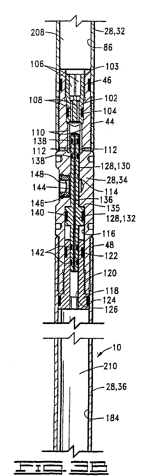
- FIGS. 3A-3C show the fluid sampler according to the present invention present invention as it is run into a wellbore.
- FIGS. 4A-4C show the sampler as a fluid sample is being taken.
- FIGS. 5A-5C show the sampler with a fluid sample captured therein.
- sampler 10 is shown disposed in an oil or gas well 12 having a wellbore 14.
- Wellbore 14 may or may not be lined with casing.
- Sampler 10 is lowered and raised relative to wellbore 14 by any one of various known means, such as a tubing string 16. It will be understood by those skilled in the art that sampler 10 can also be run on a slick line, on a wireline, and/or above or below a packer as is well known.
- Wellbore 14 is shown intersecting a subsurface formation or zone of interest 18, the flow from which is to be sampled. Fluids from formation or zone 18 flow into well 12 and are sampled by sampler 10.
- Sampler 10 is lowered from and controlled by various surface equipment schematically illustrated at 20, which is located at the surface of the well.
- sampler 10 can be used in a large sampling apparatus or carrier 22 which may hold a plurality of samplers 10, as illustrated in FIG. 2.
- Sampling apparatus or carrier 22 may be part of a downhole tool 24 such as, but not limited to, an early evaluation testing string usable in an uncased wellbore.
- Measuring instruments 26, such as pressure and temperature gauges, may also be mounted in sampling apparatus or carrier 22 along with samplers 10.
- Sampler 10 comprises a body or housing 28.
- Housing 28 includes an upper adapter 30, an upper cylinder 32, an intermediate adapter 34, a lower cylinder 36 and a lower adapter 38.
- Upper adapter 30 is attached to upper cylinder 32 at threaded connection 40, and a seal 42 provides sealing engagement between upper adapter 30 and upper cylinder 32.
- the lower end of upper cylinder 30 is attached to intermediate adapter 34 at threaded connection 44, and a seal 46 provides sealing engagement therebetween.
- Intermediate adapter 34 is attached to the upper end of lower cylinder 36 at threaded connection 48.
- the lower end of lower cylinder 36 is attached to lower adapter 38 at threaded connection 50, and a seal 52 provides sealing engagement therebetween.
- Upper adapter 30 defines a flow passageway 54 therethrough including a port 56 and a passage 58.
- Passage 58 includes a transverse portion 59.
- a check valve adapter 60 is disposed in passage 54 and connected to upper adapter 30 by a threaded connection 62.
- a seal 64 provides sealing engagement between check valve adapter 62 and upper adapter 30.
- a central opening 66 through check valve adapter 60 provides communication between port 56 and passage 58 and thus may be said to form part of passageway 54.
- a check valve such as a ball check valve 68, is disposed in upper adapter 30 below check valve adapter 60. As seen in FIG. 3A, ball check valve 68 is in an open position. When in a closed position, as shown in FIG. 5A, ball check valve 68 is adapted for sealing engagement with a seat 70 on check valve adapter 60, as will be further discussed herein.
- Upper adapter 30 defines an off-centre longitudinal bore 72 therein which intersects transverse passage portion 59 and thus is in communication with passageway 54.
- An isolation valve such as a sliding isolation valve 74, is disposed in bore 72.
- An enlarged upper portion 76 of isolation valve 74 carries a pair of seals 78 thereon. Seals 78 seal on opposite sides of horizontal portion 59 of passage 58 when isolation valve 74 is in the initial position shown in FIG. 3A.
- a smaller diameter lower portion 80 of isolation valve 74 extends downwardly from upper portion 76 and below upper adapter 30.
- Upper cylinder 32 defines a first bore 82, a smaller second bore 84, and a third bore 86 therein which is larger than second bore 84.
- a plunger 88 is disposed in upper cylinder 32 and has an enlarged upper end 90 slidably disposed within first bore 82 of the upper cylinder and a smaller lower end 92 slidably disposed in second bore 84. It will be seen that an annular area differential is defined between enlarged upper end 90 and smaller lower end 92 of plunger 88.
- Plunger 88 defines a longitudinally extending opening 93 therethrough.
- a seal 94 provides sealing engagement between upper end 90 of plunger 88 and first bore 82, and similarly, another seal 96 provides sealing engagement between lower end 92 and second bore 84.
- a floating piston 98 is disposed in third bore 86 of upper cylinder 32 and is initially spaced below plunger 88. Sealing is provided between floating piston 98 and third bore 86, such as by a plurality of seals 100.
- an orifice or restriction port adapter 102 is disposed in intermediate adapter 34 and is engaged therewith at threaded connection 103.
- a seal 104 provides sealing engagement between orifice adapter 102 and intermediate adapter 34.
- a plurality of longitudinally extending ports 106 are defined in orifice adapter 102.
- a longitudinally extending flow restriction port 108 is in communication with each of ports 106.
- Flow restriction ports 108 are sized sufficiently small to restrict fluid flow therethrough.
- Flow restriction ports 108 may also be referred to as orifices 108.
- Other flow restriction devices, such as removable orifices may also be used.
- sampler 10 includes a flow restrictor for impeding fluid flow between upper cylinder 32 and lower cylinder 36, as will be further described herein.
- orifice adapter 102 is in communication with a plurality of passageways 110, each of which having a transversely extending portion 112.
- Intermediate adapter 34 defines a first bore 114 therein and a larger second bore 116.
- First bore 114 intersects, and is in communication with, transverse portions 112 of passageways 110.
- valve adapter 118 is attached to the lower end of intermediate adapter 34 at threaded connection 120.
- a seal 122 provides sealing engagement between valve adapter 118 and intermediate adapter 34.
- Another seal 124 provides sealing engagement between valve adapter 118 and lower cylinder 36.
- Valve adapter 118 defines a bore 126 therethrough which is smaller than second bore 116 in intermediate adapter 34 and is substantially coaxial with first bore 114 and second bore 116 in the intermediate adapter.
- a control valve 128 is disposed in intermediate adapter 34 for initially isolating lower cylinder 36 from upper cylinder 32 and for placing the lower cylinder in communication with the upper cylinder when activated.
- the control valve is characterized by a slidable control valve 128 of the configuration shown in FIG. 3B.
- An upper portion 130 of control valve 128 extends into first bore 114 of intermediate adapter 34, an enlarged central portion 132 of the control valve is disposed in second bore 116 of the intermediate adapter, and a lower portion 134 extends into bore 126 of valve adapter 118.
- An upwardly facing shoulder 135 on control valve 128 extends between upper portion 130 and central portion 132.
- a central opening 136 is defined through control valve 128 and thus provides communication between first bore 114 in intermediate adapter 34 and bore 126 in valve adapter 118.
- Seals 138 provide sealing engagement between upper portion 130 of control valve 128 and first bore 114 in intermediate adapter 34. Seals 138 are disposed on opposite sides of transverse portions 112 of passageways 110 when control valve 128 is in the closed position shown in FIG. 3B, thus closing passageways 110.
- a seal 140 provides sealing engagement between central portion 132 of control valve 128 and second bore 116 of intermediate adapter 34. Seals 142 provide sealing engagement between lower portion 134 of control valve 128 and valve adapter 118.
- a transverse opening or control port 144 is defined in intermediate adapter 34, and this transverse opening intersects first bore 114.
- a control valve activator is in communication with control port 144.
- the control valve activator is characterized by a rupture disc adapter 146 with a rupture disc 148 therein. Rupture disc adapter 146 and rupture disc 148 are disposed in control port 144, and rupture disc 148 is designed to rupture when a predetermined differential pressure is placed thereacross. That is, when annulus pressure outside sampler 10 is raised to a sufficient level over the pressure in sampler 10, rupture disc 148 will rupture and open control port 144.
- the control valve activator may be referred to as an annulus pressure responsive activator.
- activators such as an electronically controlled solenoid valve, or other means for opening a port known in the art may be used, and the invention is not intended to be limited to the specific configuration shown in the drawings.
- the activator is adapted for providing communication between control valve 128 and well fluid in an outside zone outside sampler 10 when desired.
- lower adapter 134 defines a first bore 150, a smaller second bore 152 below first bore 150, and a still smaller third bore 154 which opens downwardly.
- Third bore 154 may also be referred to as a sampling port 154 and has a threaded surface 156 at the lower end thereof.
- An upwardly facing shoulder 158 extends between second bore 152 and sampling port 154.
- a plurality of transverse openings 160 provide communication between first bore 150 and an annular volume 162 defined between lower cylinder 36 and an upper end of lower adapter 38.
- a check valve 164 is disposed in lower adapter 38 for allowing fluid flow through sampling port 154 into lower cylinder 36 while preventing fluid flow from the lower cylinder outwardly through the sampling port.
- check valve 164 is characterized by a slidable check valve 164 which is slidably disposed in second bore 152 of lower adapter 38.
- Check valve 164 defines a flow passageway 166 therein which includes angularly disposed portions 168.
- check valve 164 When check valve 164 is in the open position shown in FIG. 3C, it will be seen that communication is provided through passageway 166, an annular volume 170 defined between check valve 164 and first bore 150 in lower adapter 38, ports 160 and annular volume 162.
- check valve 164 when opened, allows communication between an outside zone outside body 18 adjacent to the bottom of lower adapter 38 and the inside of lower cylinder 36 through sampling port 154.
- a check valve retainer 172 is attached to lower adapter 38 at threaded connection 174 and limits upward movement of check valve 164.
- a pair of spaced seals 176 and 178 are disposed on opposite sides of angular portions 168 of passageway 166.
- Piston 180 comprises a first or upper piston portion 182 slidably received in bore 184 defined in lower cylinder 36.
- a seal 186 provides sealing engagement between upper piston portion 182 in cylinder 36.
- Upper piston portion 182 defines a bore therein.
- An upper end 190 of a second or lower piston portion 192 is slidably received in bore 188 such that there can be relative movement between upper piston portion 182 and lower piston portion 192.
- An enlarged lower end 194 of lower piston portion 192 is slidably received in bore 184 of lower cylinder 36.
- a seal 196 provides sealing engagement between lower end 194 and lower cylinder 36.
- a plurality of radially inwardly spring biased locking dogs 198 are disposed in upper piston portion 182 and bear against upper end 190 of lower piston portion 192. Locking dogs 198 are adapted for locking engagement with a radially outwardly facing groove 200 defined in upper end 190 of lower piston portion 192. Thus, a lock is provided for locking upper and lower piston portions 182 and 192 together after predetermined relative movement therebetween, as will be further described herein.
- Lower piston portion 192 defines a central opening 202 therethrough which provides communication between the bottom of the lower piston portion and bore 188 in upper piston portion 182.
- Air cavities 202, 204 and 206 may be jointly described as an air chamber 207 in which plunger 88 is slidably disposed.
- An upper hydraulic fluid chamber 208 is defined in upper cylinder 32 between floating piston 98 and intermediate adapter 34.
- floating piston 98 is in communication with upper hydraulic fluid chamber 208 and air chamber 207, and floating piston 98 separates the upper hydraulic fluid chamber from the air chamber. It will be seen that in the initial position shown in FIG. 3B, the lower end of upper hydraulic fluid chamber 208 is closed by control valve 128.
- a lower hydraulic fluid chamber 210 is defined in lower cylinder 36 below intermediate adapter 34 and control valve 128 and above floating piston 180.
- Upper and lower hydraulic fluid chambers 208 and 210 are filled with low pressure hydraulic fluid when the apparatus is assembled.
- sampling chamber 214 is defined between floating piston 180 and check valve 164.
- sampling chamber 214 is shown to initially consist primarily of annular volume 162. As will be further described herein, sampling chamber 214 enlarges to receive a fluid sample by movement of floating piston 180.
- Sampling chamber 214 may also be referred to as a first chamber 214 in body 28
- lower hydraulic fluid chamber 210 may be referred to as a second chamber 210
- upper hydraulic fluid chamber 208 may be referred to as a third chamber 208
- air chamber 207 may be referred to as a fourth chamber 207.
- sampler 10 is run into well 12 to collect samples from within wellbore 14.
- Sampler 10 may be conveyed in downhole tool 24 by placing it in a suitable carrier or other sampling apparatus 22, as previously described and shown in FIG. 2. This protects sampler 10 and allows it to be connected in communication with the work string bore, where presumably the sampled fluid will be.
- Tubing pressure may be communicated through a connector (not shown) engaged with sampling port 154 at threaded surface 156 in the lower end of lower adapter 38, and thus, tubing pressure is communicated to sampling or first chamber 214 of sampler 10 from a zone outside the sampler. This pressure is communicated through open check valve 164 and thus to floating piston 180.
- the activator When a sample is to be taken, the activator is used to open control valve 128. As previously indicated, this activator may activate control valve 128 by various methods. In the illustrated embodiment, annulus pressure is applied in well 12 in a second zone outside sampler 10 sufficient to rupture rupture disc 148.
- the slow movement of fluid from second chamber 210 to third chamber 208 through orifices 108 allows the fluid sample to flow slowly into first chamber 214, thereby preventing fluid flashing.
- the supercharging of the fluid sample so that it is kept at a pressure above hydrostatic pressure greatly reduces or eliminates phase change degradation of the sample as sampler 10 is removed from well 12. In other words, regardless of the outside pressure conditions around sampler 10, once it is filled and locked as described, the fluid sample is above well hydrostatic pressure therein.
Landscapes
- Life Sciences & Earth Sciences (AREA)
- Engineering & Computer Science (AREA)
- Geology (AREA)
- Mining & Mineral Resources (AREA)
- Physics & Mathematics (AREA)
- Environmental & Geological Engineering (AREA)
- Fluid Mechanics (AREA)
- General Life Sciences & Earth Sciences (AREA)
- Geochemistry & Mineralogy (AREA)
- Sampling And Sample Adjustment (AREA)
Abstract
Description
- This invention relates generally to fluid sampling apparatus. In particular, a fluid sampling tool and method of use which, in response to pressure, opens to collect a fluid sample, and more particularly, to a sampling tool which provides for collection of a fluid sample without flashing of vapor in the liquid and which retains the fluid in a supercharged condition. Thus, the invention particularly relates to a non-flashing fluid sampler and method.
- In general, to obtain a sample of fluid in an oil or gas well, a fluid sampling tool is first lowered into the well on a tubing string or a wireline or a slick line. When the tool is at the desired depth, a port (one or more openings) defined in the tool is opened. The port may open in response to pressure exerted through the well fluid or in response to an electrical actuation signal from the surface. The open port admits well fluid into a sample retaining chamber within the tool. The port is thereafter closed, the tool is withdrawn from a well, and the sample is taken from the chamber for analysis.
- U. S. Patent No. 4,903,765 shows an improvement in such fluid sampling tools, wherein the fluid sampling tool is constructed to have a time delay which starts when a valve of a tool first starts to move in response to pressure from the well. This time delay provides various advantages. In one instance, the time delay allows undesired fluid such as drilling fluids to bypass the sampling tool before the valve communicates a sample port with a sample chamber and a sample of the well fluid is taken. In another instance, the time delay can reduce the dependency on accurate pressure readings and shear pins which control the opening of the valve. For example, when a maximum bottom hole pressure is measured or otherwise anticipated, shear pins providing a holding force of something less than this maximum pressure, but one which will clearly be encountered somewhere downhole despite a lack of assurance as to precisely where it will be, can be used so that the pins will break at some location above the bottom of the well. This time delay, designed with a suitable tolerance to assure reaching bottom before its expiration, is then used to allow the tool to be run on down to the well bottom, where it is ultimately automatically opened.
- U. S. Patent No. 5,058,674 provides various improvements upon a delayed opening fluid sampler of the type generally shown in US Patent No. 4,903,765. These improvements relate generally to various means for controlling the actuation of the valve which controls flow of the sample fluid to the sample chamber.
- A problem with some prior art fluid samplers is that the sample is obtained relatively quickly which can cause the fluid to flash (separation of the liquid and vapor stages) as it is flowing into the sampling chamber. This is an undesirable condition and can affect the quality of the fluid sample. The sampler of the present invention provides for controlled flowing of the fluid into the sample chamber which greatly reduces or eliminates fluid flashing.
- Another problem with some prior fluid samplers is that when they are removed from the wellbore, the reduction in hydrostatic pressure acting on the sampler as it is raised also results in fluid pressure therein being reduced. The drop in pressure can cause phase change degradation of the sample. That is, flashing can occur as the sampler is removed from the wellbore. The sampler of the present invention solves this problem by providing for the fluid sample to be trapped at well hydrostatic pressure regardless of the pressure outside the sampler. This "supercharging" of the fluid sample greatly reduces or eliminates phase change problems.
- The present invention includes a non-flashing fluid sampler used in obtaining a well fluid sample and also includes methods of sampling a well using the fluid sampler.
- The fluid sampling apparatus comprises a body having a first chamber, a second chamber, a third chamber and a sampling port defined therein. The sampling port is in communication with the first chamber and with an outside zone outside the body. The apparatus may further comprise a flow restrictor, disposed in the body between the second and third chambers, for impeding fluid flow from the second chamber to the third chamber.
- The apparatus may also comprise a control valve, disposed in the body between the second and third chambers, for initially isolating the second chamber from the third chamber and for placing the second chamber in communication with the third chamber when activated so that, as fluid flows from the second chamber to the third chamber, fluid from the outside zone may flow through the sampling port into the first chamber.
- An activator is provided for activating the control valve. In a preferred embodiment, the body further defines a control port therein which is communicated with the control valve and a second outside zone outside the body. The activator is disposed in the control port and adapted for opening the control port and activating the control valve in response to pressure from the second outside zone. The activator may be characterized as adapted for activating the control valve when a pressure differential between the second outside zone and the control valve reaches a predetermined level. This activator may be characterized by a rupture disc disposed across the control port.
- The sampling apparatus may further comprise a floating piston disposed between the first chamber and the second chamber and movable in response to fluid flow from the second chamber to the third chamber which results in fluid flow from the outside zone in communication with the sampling port into the first chamber. The floating piston preferably comprises a first piston portion and a second piston portion adjacent to the first piston portion. The first and second piston portions are relatively movable and define a variable volume therebetween. A lock is provided for locking the first and second piston portions together after predetermined relative movement therebetween. The variable volume is in communication with the sampling port and allows a portion of fluid flowing through the sampling port to flow into the variable volume before the first chamber is filled. In this way, "dirty" fluid is flowed before overall movement of the floating piston to enlarge the first chamber.
- A check valve is provided in communication with the sampling port for allowing fluid flow from the sampling port into the first chamber in response to movement of the floating piston while preventing fluid flow from the first chamber outwardly through the sampling port.
- The fluid sampling apparatus further comprises an isolation valve, disposed in the body, for allowing hydrostatic pressure from the well into the body, thereby communicating the hydrostatic pressure to the first, second and third chambers. Another check valve is provided for preventing fluid flow outwardly from the body and for trapping the hydrostatic pressure in the body.
- A second floating piston is disposed in the body and is in communication with the third chamber and movable in response to fluid flow from the second chamber to the third chamber. The apparatus further comprises a plunger for engaging the isolation valve in response to predetermined movement of the second floating piston. In one embodiment, the plunger is adjacent to the isolation valve and movable by the second floating piston in response to the predetermined movement of the second floating piston such that the isolation valve is opened. The body further defines a fourth chamber therein, and the plunger is disposed in the fourth chamber. The fourth chamber is preferably air filled.
- The plunger preferably defines a differential area thereon such that, when the hydrostatic pressure is applied to the plunger, the plunger and second floating piston are forced downwardly which raises the pressure in the first, second and third chambers of the body to a level above well hydrostatic pressure.
- The present invention also includes a method of sampling a well which comprises the step of running a fluid sampling tool into the well to a depth at which the well is to be sampled, the fluid sampling tool comprising: a body having a first chamber, a second chamber, a third chamber and a sampling port defined therein, the sampling port being communicated with the well outside the body; and a control valve disposed in the body and isolating the second chamber from the third chamber. This method further comprises the steps of activating the control valve and thereby placing the second chamber in communication with the third chamber so the fluid may flow from the second chamber to the third chamber, and flowing fluid from the well into the first chamber through the sampling port. The step of activating the control valve may comprise applying well pressure to a portion of the control valve, and in a particular embodiment, may comprise rupturing a rupture disc between the control valve and the well outside the body.
- The fluid sampling tool may further comprise a fluid flow restriction in the body between the second and third chambers. The second chamber is placed in communication with the third chamber through the fluid flow restriction so that the fluid may flow slowly from the second chamber to the third chamber.
- Stated in another way, the present invention includes a method of sampling a well which comprises the step of running a fluid sampling tool into the well to a depth at which the well is to be sampled wherein the fluid sampling tool comprises: a body defining a first chamber, a second chamber, a third chamber and a sampling port therein, said sampling port being communicated with the well outside the body; and a floating piston disposed in the body between the first and second chambers. This method further comprises the steps of flowing fluid from the second chamber to the third chamber, flowing an initial quantity of well fluid through the sampling port into a variable volume defined in the floating piston, and, after flowing the initial quantity of well fluid, flowing an additional amount of fluid into the first chamber.
- Stated in still another way, the present invention includes a method of sampling a well which comprises the step of running a fluid sampling tool into the well at a depth at which the well is to be sampled, wherein the sampling tool comprises: a body defining a first chamber, a second chamber, a third chamber and a sampling port therein, the sampling port being communicated with the well outside the body; and an isolation valve disposed in the body. This method further comprises the steps of flowing fluid from the second chamber to the third chamber, flowing a fluid sample through the sampling port into the first chamber, and activating the isolation valve for allowing hydrostatic pressure from the well into the body and thereby communicating the hydrostatic pressure to the first, second and third chambers. This method may comprise the additional step of preventing fluid flow outwardly from the body and trapping the hydrostatic pressure in the body. This method may also comprise the additional step of raising the fluid pressure in the first, second and third chambers of the body to a level above well hydrostatic pressure.
- According to another aspect of the invention there is provided a fluid sampling apparatus comprising: a body having a first chamber, a second chamber, a third chamber, and a sampling port defined therein, the sampling port being in communication with the first chamber and an outside zone outside the body; and a control valve, disposed in the body between the second and third chambers, for initially isolating the second chamber from the third chamber and for placing the second chamber in communication with the third chamber when activated so that, as fluid flows from the second chamber to the third chamber, fluid from the outside zone may flow through the sampling port into the first chamber.
- In an embodiment, the apparatus further comprises an activator for activating the control valve. The body may further define a control port therein, the control port being communicated with the control valve and a second outside zone outside the body, and the activator may be disposed in the control port and adapted for opening the control port and activating the control valve in response to pressure from the second outside zone.
- In an embodiment, the activator activates the control valve when a pressure differential between the second outside zone and the control valve reaches a predetermined level. The activator may comprise a rupture disc disposed across the control port.
- In an embodiment, the apparatus further comprises a floating piston disposed between the first and second chambers. The floating piston may comprises a first piston portion, and a second piston portion slidable with respect to the first piston portion such that a variable volume is defined therebetween.
- In an embodiment, the apparatus further comprises a lock for locking the first and second piston portions to one another after predetermined movement of the second piston portion with respect to the first piston portion.
- The variable volume defined in the floating piston may be in communication with the sampling port.
- In an embodiment, the apparatus further comprises a ball check valve disposed in the sampling port for allowing fluid flow through the sampling port into the first chamber while preventing fluid flow from the first chamber outwardly through the sampling port.
- In an embodiment, the apparatus further comprises an isolation valve for allowing outside hydrostatic pressure into the body after a predetermined volume of fluid has flowed from the second chamber to the third chamber.
- In an embodiment, the apparatus further comprises a back check valve for trapping the hydrostatic pressure in the body.
- In an embodiment, the apparatus further comprises a second floating piston in communication with the third chamber and movable in response to fluid flow from the second chamber to the third chamber.
- In an embodiment, the apparatus further comprises a plunger adjacent to the isolation valve and engageable by the second floating piston such that the plunger is moved in response to the predetermined movement of the second floating piston, thereby engaging and opening the isolation valve.
- In an embodiment, the body further defines an air chamber therein, and the plunger is disposed in the air chamber.
- The plunger may define a differential area thereon such that, when the hydrostatic pressure is applied thereto, the plunger and floating piston are forced downwardly, thereby raising a pressure of fluid in the body to a level above the hydrostatic pressure.
- A flow restrictor may be disposed in the body between the second and third chambers for impeding fluid flow from the second chamber to the third chamber.
- According to another aspect of the invention there is provided a fluid sampling apparatus comprising: a body having a first chamber, a second chamber, a third chamber and a sampling port defined therein, the sampling port being in communication with the first chamber and an outside zone outside the body; and a floating piston disposed between the first chamber and the second chamber and movable in response to fluid flow from the second chamber to the third chamber and resulting fluid flow from the outside zone into the first chamber through the sampling port.
- In an embodiment, the floating piston comprises a first piston portion, and a second piston portion adjacent to the first piston portion, the first and second piston portions being relatively movable and defining a variable volume therebetween. The variable volume may be in communication with the sampling port.
- In an embodiment, the apparatus further comprises a lock for locking the first and second piston portions together after predetermined relative movement between the first and second piston portions.
- The apparatus may further comprise a back check valve disposed in the sampling port for allowing fluid flow through the sampling port into the first chamber in response to movement of the floating piston while preventing fluid flow from the first chamber outwardly through the sampling port.
- The apparatus may further comprise an isolation valve for allowing outside hydrostatic pressure into the body after a predetermined volume of fluid has flowed from the second chamber to the third chamber.
- In an embodiment, the apparatus further comprises a back check valve for locking the hydrostatic pressure in the body.
- In an embodiment, the apparatus further comprises a second floating piston in communication with the third chamber and movable in response to fluid flow from the second chamber to the third chamber.
- In an embodiment, the apparatus further comprises a plunger for engaging and opening the isolation valve in response to predetermined movement of the second floating piston.
- In an embodiment, the body further defines an air chamber therein, and the plunger is disposed in the air chamber.
- The plunger may define a differential area thereon such that, when the hydrostatic pressure is applied thereto, the plunger and second floating piston are moved downwardly, thereby raising a pressure of fluid in the body to a level above the hydrostatic pressure.
- In an embodiment, The apparatus further comprises a control valve, disposed in the body between the second and third chambers, for initially isolating the second chamber from the third chamber and for allowing fluid flow from the second chamber to the third chamber when activated.
- The apparatus may further comprise an activator for activating the control valve. The body further may defines a control port therein, the control port being in communication with a second outside zone outside the body, and the activator may be disposed in the control port and may be adapted for opening the control port and activating the control valve in response to outside pressure from the second outside zone. The activator may be adapted for activating the control valve when a predetermined pressure differential between the second outside zone and the control valve is reached. The activator may comprise a rupture disc disposed across the control port.
- A flow restrictor may be disposed in the body between the second and third chambers for impeding fluid flow from the second chamber to the third chamber.
- According to another aspect of the invention there is provided a fluid sampling apparatus for use adjacent to a zone of interest in a well, the apparatus comprising: a body having a plurality of chambers and a sampling port defined therein, the sampling port being in communication with one of the chambers and an outside zone outside the body; an isolation valve, disposed in the body, for allowing hydrostatic pressure from the well into the body and thereby communicating the hydrostatic pressure to the chambers; and a check valve for preventing fluid flow outwardly from the body and thereby trapping the hydrostatic pressure in the body.
- In an embodiment, the one chamber is a first chamber; and the plurality of chambers further comprises a second chamber and a third chamber; and the apparatus further comprises a floating piston in communication with the third chamber and movable in response to fluid flow from the second chamber to the third chamber.
- In an embodiment, the apparatus further comprises a plunger for opening the isolation valve in response to predetermined movement of the floating piston.
- In an embodiment, the body further defines an air chamber therein; and the plunger is disposed in the air chamber.
- The plunger may define a differential area thereon such that, when the hydrostatic pressure is applied thereto, the plunger and floating piston are forced downwardly, thereby raising a pressure of fluid in the body to a level above the hydrostatic pressure. Fluid pressure in each of the first, second and third chambers may be raised to the level above the hydrostatic pressure. The differential area may be defined as the difference in a cross-sectional area of an upper end of the plunger and a cross-sectional area of a lower end of the plunger, the lower end of the plunger being smaller than the upper end of the plunger.
- In an embodiment, the apparatus further comprises a seal disposed between the body and the upper end of the plunger; and another seal disposed between the body and the lower end of the plunger.
- The check valve may comprise a ball check valve in communication with the isolation valve. The check valve may comprise a slidable check valve disposed between the sampling port and the one chamber.
- In an embodiment, the apparatus further comprises a floating piston disposed between two of the chambers. The floating piston may comprises a first piston portion; and a second piston portion relatively movable with respect to the first piston portion, the first and second piston portions defining a variable volume therebetween. The variable volume defined in the floating piston may be in communication with the sampling port.
- In an embodiment, the apparatus further comprises a lock for locking the first and second piston portions to one another after predetermined relative movement between the first and second piston portions.
- In an embodiment, the one chamber is a first chamber; and the plurality of chambers further comprises a second chamber and a third chamber; and the apparatus further comprises a control valve, disposed in the body between the second and third chambers, for initially isolating the second chamber from the third chamber and for allowing fluid flow from the second chamber to the third chamber when activated.
- In an embodiment, the apparatus further comprises an activator for activating the control valve. The body may further define a control port therein, the control port being communicated with a second outside zone outside the body; and the activator may be disposed in the control port and adapted for opening the control port in response to outside pressure from the second outside zone. The activator may be adapted for activating the control valve when a pressure differential between the second outside zone and the control valve reaches a predetermined level. The activator may comprise a rupture disc disposed across the control port.
- In an embodiment, the one chamber is a first chamber; and the plurality of chambers further comprises a second chamber and a third chamber; and the apparatus further comprises a flow restrictor, disposed in the body between the second and third chambers, for impeding fluid flow from the second chamber to the third chamber.
- According to another aspect of the invention there is provided a fluid sampling apparatus for use adjacent to a zone of interest in a well, the apparatus comprising: a body having a first chamber, a second chamber and a sampling port defined therein, the sampling port being in communication with the first chamber and an outside zone outside the body; and a floating piston disposed between the first chamber and the second chamber, the piston defining a variable volume therein in communication with the first chamber.
- The variable volume may be fillable by fluid flowing from the outside zone into the first chamber through the sampling port in response to fluid flowing out the second chamber; and the piston may be movable in response to further fluid flow out the second chamber and resulting fluid flow from the outside zone into the first chamber through the sampling port.
- The piston may comprises a first piston portion, and a second piston portion adjacent to the first piston portion, the variable volume being defined between the first and second piston portions. The first and second piston portions may be relatively movable.
- In an embodiment, the apparatus further comprises a lock for locking the first and second piston portions together after predetermined relative movement therebetween. The lock may comprise a locking dog disposed in one of the first and second piston portions engageable with a groove defined in the other of the first and second piston portions.
- In an embodiment, the first piston portion defines a bore therein, and at least a portion of the second piston portion is slidably received in the bore.
- In an embodiment, the apparatus further comprises a first seal for sealing between the first piston portion and the body, and a second seal for sealing between the second piston portion and the body.
- According to another aspect of the invention there is provided a method of sampling a well, comprising the steps of: (a) running a fluid sampling tool into the well to a depth at which the well is to be sampled, the fluid sampling tool comprising a body having a first chamber, a second chamber, a third chamber and a sampling port defined therein, the sampling port being communicated with the well outside the body, and a control valve disposed in the body and initially isolating the second chamber from the third chamber; (b) activating the control valve and thereby placing the second chamber in communication with the third chamber so that fluid may flow from the second chamber to the third chamber; and (c) flowing fluid from the well into the first chamber through the sampling port.
- In an embodiment, step (b) comprises applying well annulus pressure to a portion of the control valve. Step (b) may further comprise rupturing a rupture disc between the control valve and the well outside the body.
- The sampling tool may further comprise a floating piston disposed between the first and second chambers, and step (c) may comprise flowing fluid into a variable volume defined in the floating piston.
- In an embodiment, the method includes the following step: (d) after step (c), allowing hydrostatic pressure into the body and communicating the hydrostatic pressure to the first, second and third chambers.
- In an embodiment, the method includes the following step: (e) after step (d), trapping the hydrostatic pressure in the body and preventing outward fluid flow from the sampling tool.
- The fluid sampling tool may further comprise a plunger having a differential area defined thereon and disposed in the body, the method may further comprise (e) after step (d), applying the hydrostatic pressure to the differential area on the plunger so that the plunger is moved to raise a pressure in the first, second and third chambers to a level above the hydrostatic pressure.
- In an embodiment, the method further comprises: (d) after step (c), raising a pressure fluid in the first chamber to a level above well hydrostatic pressure.
- In an embodiment, the sampling tool further comprises a fluid flow restriction in the body between the second and third chambers, and step (b) comprises placing the second chamber in communication with the third chamber through the fluid flow restriction so that fluid may flow slowly from the second chamber to the third chamber.
- According to another aspect of the invention there is provided a method of sampling a well, the method comprising the steps of: (a) running a fluid sampling tool into the well to a depth at which the well is to be sampled, the fluid sampling tool comprising a body defining a first chamber, a second chamber, a third chamber and a sampling port therein, the sampling port being communicated with the well outside the body; and a floating piston disposed in the body between the first and second chambers; and (b) flowing fluid from the second chamber to the third chamber; (c) flowing an initial quantity of well fluid through the sampling port into a variable volume defined in the floating piston; and (d) after step (c), flowing an additional amount of fluid into the first chamber.
- In an embodiment, step (b) comprises flowing fluid from the second chamber to the third chamber through a fluid flow restriction.
- In an embodiment, step (b) comprises opening a control valve between the second and third chambers.
- In an embodiment, the method further comprises the step of: (d) after step (c), allowing hydrostatic pressure into the body and communicating the hydrostatic pressure to the first, second and third chambers.
- In an embodiment, the method further comprises the step of: (e) after step (d), trapping the hydrostatic pressure in the body and preventing outward fluid flow from the sampling tool.
- In an embodiment, the fluid sampling tool further comprises a plunger having a differential area defined thereon and disposed in the body; and the method further comprising: (e) after step (d), applying the hydrostatic pressure to the differential area on the plunger, thereby raising a pressure of fluid in the first, second and third chambers to a level above the hydrostatic pressure.
- In an embodiment, the method further comprises the step of: (e) after step (d), raising a pressure of the fluid in the first chamber to a level above well hydrostatic pressure.
- According to another aspect of the invention there is provided a method of sampling a well, the method comprising: (a) running a fluid sampling tool into the well to a depth at which the well is to be sampled, the fluid sampling tool comprising a body defining a first chamber, a second chamber, a third chamber and a sampling port therein, the sampling port being communicated with the well outside the body, and an isolation valve disposed in the body; (b) flowing fluid from the second chamber to the third chamber; (c) flowing a fluid sample through the sampling port into the first chamber; and (d) activating the isolation valve for allowing hydrostatic pressure from the well into the body and thereby communicating the hydrostatic pressure to the first, second and third chambers.
- In an embodiment, the method further comprises: (e) preventing fluid flow outwardly from the body and trapping the hydrostatic pressure in the body.
- In an embodiment, the sampling tool further comprises a floating piston disposed in the body between the first and second chambers; and step (c) comprises flowing a portion of well fluid into a variable volume defined in the floating piston.
- In an embodiment, step (b) comprises flowing fluid from the second chamber to the third chamber through a fluid flow restriction.
- In an embodiment, the method further comprises: (e) after step (d), preventing fluid flow outwardly from the first chamber through the sampling port.
- In an embodiment, the method further comprises: (e) after step (d), raising pressure in the first, second and third chambers to a level above the hydrostatic pressure.
- In an embodiment, the fluid sampling tool further comprises a plunger disposed in the body and defining a differential area thereon; and step (e) comprises applying the hydrostatic pressure to the differential area on the plunger and thereby forcing the plunger away from the isolation valve to increase the pressure in the first, second and third chambers.
- Reference is now made to the accompanying drawings, in which:
- FIG. 1 is a schematic block diagram depicting an embodiment of a non-flashing fluid sampler according to the present invention in place within a well which is to be sampled.
- FIG. 2 schematically shows a plurality of samplers according to the present invention mounted in a sampling apparatus or carrier positioned within a well.
- FIGS. 3A-3C show the fluid sampler according to the present invention present invention as it is run into a wellbore.
- FIGS. 4A-4C show the sampler as a fluid sample is being taken.
- FIGS. 5A-5C show the sampler with a fluid sample captured therein.
- Referring now to the drawings, and more particularly to FIG. 1, the non-flashing downhole fluid sampler of the present invention is shown and generally designated by the numeral 10.
Sampler 10 is shown disposed in an oil or gas well 12 having awellbore 14.Wellbore 14 may or may not be lined with casing.Sampler 10 is lowered and raised relative to wellbore 14 by any one of various known means, such as atubing string 16. It will be understood by those skilled in the art that sampler 10 can also be run on a slick line, on a wireline, and/or above or below a packer as is well known.Wellbore 14 is shown intersecting a subsurface formation or zone ofinterest 18, the flow from which is to be sampled. Fluids from formation orzone 18 flow into well 12 and are sampled bysampler 10. -
Sampler 10 is lowered from and controlled by various surface equipment schematically illustrated at 20, which is located at the surface of the well. - Another particular environment in which sampler 10 can be used is in a large sampling apparatus or
carrier 22 which may hold a plurality ofsamplers 10, as illustrated in FIG. 2. Sampling apparatus orcarrier 22 may be part of adownhole tool 24 such as, but not limited to, an early evaluation testing string usable in an uncased wellbore. Measuringinstruments 26, such as pressure and temperature gauges, may also be mounted in sampling apparatus orcarrier 22 along withsamplers 10. - Referring now to FIGS. 3A-3C, the details of
sampler 10 will be discussed.Sampler 10 comprises a body or housing 28. Housing 28 includes an upper adapter 30, an upper cylinder 32, an intermediate adapter 34, a lower cylinder 36 and alower adapter 38. - Upper adapter 30 is attached to upper cylinder 32 at threaded
connection 40, and a seal 42 provides sealing engagement between upper adapter 30 and upper cylinder 32. The lower end of upper cylinder 30 is attached to intermediate adapter 34 at threadedconnection 44, and aseal 46 provides sealing engagement therebetween. Intermediate adapter 34 is attached to the upper end of lower cylinder 36 at threadedconnection 48. The lower end of lower cylinder 36 is attached tolower adapter 38 at threadedconnection 50, and aseal 52 provides sealing engagement therebetween. - Upper adapter 30 defines a flow passageway 54 therethrough including a port 56 and a passage 58. Passage 58 includes a
transverse portion 59. Acheck valve adapter 60 is disposed in passage 54 and connected to upper adapter 30 by a threadedconnection 62. Aseal 64 provides sealing engagement betweencheck valve adapter 62 and upper adapter 30. A central opening 66 throughcheck valve adapter 60 provides communication between port 56 and passage 58 and thus may be said to form part of passageway 54. A check valve, such as aball check valve 68, is disposed in upper adapter 30 belowcheck valve adapter 60. As seen in FIG. 3A,ball check valve 68 is in an open position. When in a closed position, as shown in FIG. 5A,ball check valve 68 is adapted for sealing engagement with aseat 70 oncheck valve adapter 60, as will be further discussed herein. - Upper adapter 30 defines an off-centre
longitudinal bore 72 therein which intersectstransverse passage portion 59 and thus is in communication with passageway 54. An isolation valve, such as a sliding isolation valve 74, is disposed inbore 72. An enlarged upper portion 76 of isolation valve 74 carries a pair ofseals 78 thereon.Seals 78 seal on opposite sides ofhorizontal portion 59 of passage 58 when isolation valve 74 is in the initial position shown in FIG. 3A. A smaller diameter lower portion 80 of isolation valve 74 extends downwardly from upper portion 76 and below upper adapter 30. - Upper cylinder 32 defines a
first bore 82, a smaller second bore 84, and athird bore 86 therein which is larger thansecond bore 84. A plunger 88 is disposed in upper cylinder 32 and has an enlarged upper end 90 slidably disposed withinfirst bore 82 of the upper cylinder and a smaller lower end 92 slidably disposed insecond bore 84. It will be seen that an annular area differential is defined between enlarged upper end 90 and smaller lower end 92 of plunger 88. Plunger 88 defines alongitudinally extending opening 93 therethrough. Aseal 94 provides sealing engagement between upper end 90 of plunger 88 and first bore 82, and similarly, anotherseal 96 provides sealing engagement between lower end 92 andsecond bore 84. - A floating
piston 98 is disposed inthird bore 86 of upper cylinder 32 and is initially spaced below plunger 88. Sealing is provided between floatingpiston 98 andthird bore 86, such as by a plurality ofseals 100. - Referring now to FIG. 3B, an orifice or
restriction port adapter 102 is disposed in intermediate adapter 34 and is engaged therewith at threadedconnection 103. Aseal 104 provides sealing engagement betweenorifice adapter 102 and intermediate adapter 34. A plurality of longitudinally extendingports 106 are defined inorifice adapter 102. A longitudinally extendingflow restriction port 108 is in communication with each ofports 106.Flow restriction ports 108 are sized sufficiently small to restrict fluid flow therethrough.Flow restriction ports 108 may also be referred to asorifices 108. Other flow restriction devices, such as removable orifices may also be used. Thus, it may be said thatsampler 10 includes a flow restrictor for impeding fluid flow between upper cylinder 32 and lower cylinder 36, as will be further described herein. - The lower end of
orifice adapter 102 is in communication with a plurality ofpassageways 110, each of which having a transversely extendingportion 112. - Intermediate adapter 34 defines a
first bore 114 therein and a largersecond bore 116. First bore 114 intersects, and is in communication with,transverse portions 112 ofpassageways 110. - A
valve adapter 118 is attached to the lower end of intermediate adapter 34 at threadedconnection 120. Aseal 122 provides sealing engagement betweenvalve adapter 118 and intermediate adapter 34. Anotherseal 124 provides sealing engagement betweenvalve adapter 118 and lower cylinder 36.Valve adapter 118 defines abore 126 therethrough which is smaller thansecond bore 116 in intermediate adapter 34 and is substantially coaxial withfirst bore 114 andsecond bore 116 in the intermediate adapter. - A control valve 128 is disposed in intermediate adapter 34 for initially isolating lower cylinder 36 from upper cylinder 32 and for placing the lower cylinder in communication with the upper cylinder when activated. In the preferred embodiment, the control valve is characterized by a slidable control valve 128 of the configuration shown in FIG. 3B. An upper portion 130 of control valve 128 extends into
first bore 114 of intermediate adapter 34, an enlarged central portion 132 of the control valve is disposed insecond bore 116 of the intermediate adapter, and a lower portion 134 extends intobore 126 ofvalve adapter 118. An upwardly facingshoulder 135 on control valve 128 extends between upper portion 130 and central portion 132. Acentral opening 136 is defined through control valve 128 and thus provides communication betweenfirst bore 114 in intermediate adapter 34 and bore 126 invalve adapter 118. -
Seals 138 provide sealing engagement between upper portion 130 of control valve 128 andfirst bore 114 in intermediate adapter 34.Seals 138 are disposed on opposite sides oftransverse portions 112 ofpassageways 110 when control valve 128 is in the closed position shown in FIG. 3B, thus closingpassageways 110. Aseal 140 provides sealing engagement between central portion 132 of control valve 128 andsecond bore 116 of intermediate adapter 34.Seals 142 provide sealing engagement between lower portion 134 of control valve 128 andvalve adapter 118. - A transverse opening or control
port 144 is defined in intermediate adapter 34, and this transverse opening intersectsfirst bore 114. A control valve activator is in communication withcontrol port 144. In the preferred embodiment, the control valve activator is characterized by arupture disc adapter 146 with arupture disc 148 therein.Rupture disc adapter 146 andrupture disc 148 are disposed incontrol port 144, andrupture disc 148 is designed to rupture when a predetermined differential pressure is placed thereacross. That is, when annulus pressure outsidesampler 10 is raised to a sufficient level over the pressure insampler 10,rupture disc 148 will rupture andopen control port 144. In this embodiment, the control valve activator may be referred to as an annulus pressure responsive activator. However, other types of activators, such as an electronically controlled solenoid valve, or other means for opening a port known in the art may be used, and the invention is not intended to be limited to the specific configuration shown in the drawings. Basically, the activator is adapted for providing communication between control valve 128 and well fluid in an outside zone outsidesampler 10 when desired. - Referring now to FIG. 3C, it will be seen that lower adapter 134 defines a
first bore 150, a smallersecond bore 152 belowfirst bore 150, and a still smallerthird bore 154 which opens downwardly.Third bore 154 may also be referred to as asampling port 154 and has a threadedsurface 156 at the lower end thereof. An upwardly facingshoulder 158 extends betweensecond bore 152 andsampling port 154. - A plurality of
transverse openings 160 provide communication betweenfirst bore 150 and an annular volume 162 defined between lower cylinder 36 and an upper end oflower adapter 38. - A
check valve 164 is disposed inlower adapter 38 for allowing fluid flow throughsampling port 154 into lower cylinder 36 while preventing fluid flow from the lower cylinder outwardly through the sampling port. In the preferred embodiment,check valve 164 is characterized by aslidable check valve 164 which is slidably disposed insecond bore 152 oflower adapter 38.Check valve 164 defines aflow passageway 166 therein which includes angularly disposedportions 168. - When
check valve 164 is in the open position shown in FIG. 3C, it will be seen that communication is provided throughpassageway 166, anannular volume 170 defined betweencheck valve 164 andfirst bore 150 inlower adapter 38,ports 160 and annular volume 162. In other words,check valve 164, when opened, allows communication between an outside zone outsidebody 18 adjacent to the bottom oflower adapter 38 and the inside of lower cylinder 36 throughsampling port 154. Acheck valve retainer 172 is attached tolower adapter 38 at threadedconnection 174 and limits upward movement ofcheck valve 164. - A pair of spaced
seals angular portions 168 ofpassageway 166. Whencheck valve 164 is in the closed position shown in FIG. 5C, it will be seen that seals 176 and 178 provide sealing engagement betweencheck valve 164 andsecond bore 152 oflower adapter 38 to prevent communication between lower cylinder 36 and the lower end of the lower adapter, as will be discussed further herein. - Disposed above
lower adapter 38 is an extendable floatingpiston 180.Piston 180 comprises a first orupper piston portion 182 slidably received inbore 184 defined in lower cylinder 36. Aseal 186 provides sealing engagement betweenupper piston portion 182 in cylinder 36. -
Upper piston portion 182 defines a bore therein. Anupper end 190 of a second orlower piston portion 192 is slidably received inbore 188 such that there can be relative movement betweenupper piston portion 182 andlower piston portion 192. An enlarged lower end 194 oflower piston portion 192 is slidably received inbore 184 of lower cylinder 36. - A
seal 196 provides sealing engagement between lower end 194 and lower cylinder 36. - A plurality of radially inwardly spring biased locking
dogs 198 are disposed inupper piston portion 182 and bear againstupper end 190 oflower piston portion 192. Lockingdogs 198 are adapted for locking engagement with a radially outwardly facinggroove 200 defined inupper end 190 oflower piston portion 192. Thus, a lock is provided for locking upper andlower piston portions -
Lower piston portion 192 defines acentral opening 202 therethrough which provides communication between the bottom of the lower piston portion and bore 188 inupper piston portion 182. - When
sampler 10 is made up in the configuration shown in FIGS. 3A-3C, a number of chambers are defined therein. Anair cavity 202 is defined between upper adapter 30 and plunger 88 andcavity 202 is initially filled with atmospheric air. Below upper end 90 of plunger 88 an annular air cavity 204 is defined and also initially filled with atmospheric air. Still another air cavity 206 is defined between plunger 88 and floatingpiston 98 in upper cylinder 32.Opening 93 through plunger 88 insures that pressure is equalized betweenair cavity 202 and air cavity 206.Air cavities 202, 204 and 206 may be jointly described as an air chamber 207 in which plunger 88 is slidably disposed. - An upper hydraulic
fluid chamber 208 is defined in upper cylinder 32 between floatingpiston 98 and intermediate adapter 34. Thus, floatingpiston 98 is in communication with upper hydraulicfluid chamber 208 and air chamber 207, and floatingpiston 98 separates the upper hydraulic fluid chamber from the air chamber. It will be seen that in the initial position shown in FIG. 3B, the lower end of upper hydraulicfluid chamber 208 is closed by control valve 128. - Referring to FIGS. 3B and 3C, a lower
hydraulic fluid chamber 210 is defined in lower cylinder 36 below intermediate adapter 34 and control valve 128 and above floatingpiston 180. Upper and lowerhydraulic fluid chambers - A
sampling chamber 214 is defined between floatingpiston 180 andcheck valve 164. In FIG. 3C,sampling chamber 214 is shown to initially consist primarily of annular volume 162. As will be further described herein,sampling chamber 214 enlarges to receive a fluid sample by movement of floatingpiston 180. - Sampling
chamber 214 may also be referred to as afirst chamber 214 in body 28, lowerhydraulic fluid chamber 210 may be referred to as asecond chamber 210, upper hydraulicfluid chamber 208 may be referred to as athird chamber 208, and air chamber 207 may be referred to as a fourth chamber 207. - In operation,
sampler 10 is run into well 12 to collect samples from withinwellbore 14.Sampler 10 may be conveyed indownhole tool 24 by placing it in a suitable carrier orother sampling apparatus 22, as previously described and shown in FIG. 2. This protectssampler 10 and allows it to be connected in communication with the work string bore, where presumably the sampled fluid will be. Tubing pressure may be communicated through a connector (not shown) engaged withsampling port 154 at threadedsurface 156 in the lower end oflower adapter 38, and thus, tubing pressure is communicated to sampling orfirst chamber 214 ofsampler 10 from a zone outside the sampler. This pressure is communicated throughopen check valve 164 and thus to floatingpiston 180. Those skilled in the art will see that this tubing pressure is thereby communicated to the hydraulic fluid in lower hydraulic fluid orsecond chamber 210. Because control valve 128 is initially closed, as seen in FIG. 3B, the hydraulic fluid insecond chamber 210 is not allowed to flow into upper hydraulic fluid orthird chamber 208, and therefore, wellbore fluid is prevented from enteringsampler 10. - When a sample is to be taken, the activator is used to open control valve 128. As previously indicated, this activator may activate control valve 128 by various methods. In the illustrated embodiment, annulus pressure is applied in well 12 in a second zone outside
sampler 10 sufficient to rupturerupture disc 148. - Referring now also to FIGS. 4A-4C, it will be seen that the well annulus fluid pressure is applied to
shoulder 135 on central portion 132 of control valve 128, causing the control valve to be moved downwardly to the open position shown in FIG. 4B in which central portion 132 engages the top ofvalve adapter 118. When control valve 128 is opened,central opening 136 thereof is placed in communication withtransverse portions 112 ofpassageways 110 and thus in communication withorifices 108. As previously stated,orifices 108 act as a flow restrictor for impeding fluid flow fromsecond chamber 210 intothird chamber 208. That is, this flow restrictor allows higher pressure hydraulic fluid insecond chamber 210 to bleed slowly across the fluid restriction intothird chamber 208. - As well fluid slowly enters
sampler 10, the hydraulic fluid insecond chamber 210 is displaced slowly intothird chamber 208.Upper piston portion 182 of floatingpiston 180 moves upwardly within lower cylinder 36, whilelower piston portion 192 initially remains substantially stationary. Asupper piston portion 182 moves upwardly, thus extending floatingpiston 180, avariable volume 212 is formed and enlarged within floatingpiston 180. "Dirty" oil which initially flows intosampler 10 is drawn intovolume 212 in floatingpiston assembly 180. In this way, contaminated oil, mud, etc., is separated from the clean oil sample to be taken subsequently. - Eventually,
upper piston portion 182 of floatingpiston 180 moves sufficiently upwardly so that lockingdogs 198 are aligned withgroove 200 inlower piston portion 192. Because lockingdogs 198 are radially inwardly biased, they will move inwardly to engagegroove 200 so thatupper piston portion 182 andlower piston portion 192 are locked together, and these components of floatingpiston 180 move together from then on. That is, after floatingpiston 180 is fully extended, the entire floating piston will start moving inside lower cylinder 36, as seen in FIG. 4C, thereby enlargingfirst chamber 214. As floatingpiston 180 moves upwardly, the hydraulic fluid insecond chamber 210 above floatingpiston 180 will continue to flow intothird chamber 208. This causes floatingpiston 98 in upper cylinder 32 to be moved upwardly until it engages the lower end of plunger 88, as seen in FIG. 4A. - Eventually, enough fluid will enter
third chamber 208 so that floatingpiston 98 forces plunger 88 upwardly to engage lower portion 80 of isolation valve 74, thus causing upper isolation valve 74 to be moved upwardly, as seen in FIG. 4A, until the upper isolation valve reaches the open position shown in FIG. 5A. When isolation valve 74 is in this open position shown, outside hydrostatic pressure is allowed to flow into air or fourth chamber 207 through passageway 54. This hydrostatic fluid pressure acts against the area differential defined between enlarged upper end 90 and lower end 92 of plunger 88 and forces plunger 88, and thus floatingpiston 98, downwardly. This area is equal to the cross-sectional area of upper end 90 minus the cross-sectional area of lower end 92. The downward movement causes some reverse fluid flow and increased pressure in second andthird chambers first chamber 214. This causescheck valve 164 to be moved to the closed position shown in FIG. 5C. - It will be seen by those skilled in the art that the hydraulic fluid and the fluid sample are thus pressurized to a pressure above the well hydrostatic pressure.
Ball check valve 68 in passageway 54 of upper adapter 30 will close and trap the hydrostatic pressure insidesampler 10 which continues to act downwardly on plunger 88.Sampler 10 may then be retrieved with the fluid sample contained therein insample chamber 214 in its "supercharged" condition at a pressure above the well hydrostatic pressure. - The slow movement of fluid from
second chamber 210 tothird chamber 208 throughorifices 108 allows the fluid sample to flow slowly intofirst chamber 214, thereby preventing fluid flashing. The supercharging of the fluid sample so that it is kept at a pressure above hydrostatic pressure greatly reduces or eliminates phase change degradation of the sample assampler 10 is removed from well 12. In other words, regardless of the outside pressure conditions aroundsampler 10, once it is filled and locked as described, the fluid sample is above well hydrostatic pressure therein. - It will be seen, therefore, that the non-flashing downhole fluid sampler of the present invention is well adapted to carry out the ends and advantages mentioned, as well as those inherent therein. While a presently preferred embodiment of the apparatus and method of use has been shown for the purposes of this disclosure, numerous changes in the arrangement and construction of parts and steps may be made by those skilled in the art. It will be appreciated that modifications may be made.
Claims (10)
- A fluid sampling apparatus (10) comprising: a body (28) having a first chamber (214), a second chamber (210), a third chamber (208), and a sampling port (154) defined therein, the sampling port (154) being in communication with the first chamber (214) and an outside zone outside the body; and a control valve (128), disposed in the body (28) between the second and third chambers (210, 208), for initially isolating the second chamber (210) from the third chamber (208) and for placing the second chamber (210) in communication with the third chamber (208) when activated so that, as fluid flows from the second chamber (210) to the third chamber (208), fluid from the outside zone may flow through the sampling port (154) into the first chamber (214).
- Apparatus (10) according to claim 1, further comprising an activator (148) for activating the control valve (128).
- Apparatus (10) according to claim 2, wherein the body (28) further defines a control port (144) therein, the control port (144) being communicated with the control valve (128) and a second outside zone outside the body, and the activator (148) is disposed in the control port (144) and adapted for opening the control port (144) and activating the control valve (128) in response to pressure from the second outside zone.
- A fluid sampling apparatus (10) comprising: a body (28) having a first chamber (214), a second chamber (210), a third chamber (208) and a sampling port (154) defined therein, the sampling port (154) being in communication with the first chamber (214) and an outside zone outside the body; and a floating piston (180) disposed between the first chamber (214) and the second chamber (210) and movable in response to fluid flow from the second chamber (210) to the third chamber (208) and resulting fluid flow from the outside zone into the first chamber (214) through the sampling port (154).
- Apparatus (10) according to claim 4, wherein the floating piston (180) comprises a first piston portion (182), and a second piston portion (192) adjacent to the first piston portion (182), the first and second piston portions (182, 192) being relatively movable and defining a variable volume therebetween.
- Apparatus (10) according to claim 5, further comprising a lock for locking the first and second piston portions (182, 192) together after predetermined relative movement between the first and second piston portions (182, 192).
- A fluid sampling apparatus (10) for use adjacent to a zone of interest in a well, the apparatus comprising: a body (28) having a plurality of chambers (214, 210, 208) and a sampling port (154) defined therein, the sampling port (154) being in communication with one of the chambers (214, 210, 208) and an outside zone outside the body; an isolation valve (74) disposed in the body (28) for allowing hydrostatic pressure from the well into the body (28) and thereby communicating the hydrostatic pressure to the chambers (214, 210, 208); and a check valve (68) for preventing fluid flow outwardly from the body (28) and thereby trapping the hydrostatic pressure in the body (28).
- Apparatus according to claim 7, wherein the one of the chambers (214, 210, 208) with which the sampling port (154) is in communication is a first chamber (214) and the others of the chambers (214, 210, 208) comprise a second chamber (210) and a third chamber (208), the apparatus further comprising a floating piston (98) in communication with the third chamber (208) and movable in response to fluid flow from the second chamber (210) to the third chamber (208).
- A fluid sampling apparatus (10) for use adjacent to a zone of interest in a well, the apparatus (10) comprising: a body (28) having a first chamber (214), a second chamber (210) and a sampling port (154) defined therein, the sampling port (154) being in communication with the first chamber (214) and an outside zone outside the body (210); and a floating piston (180) disposed between the first chamber (214) and the second chamber (210), the piston (180) defining a variable volume therein in communication with the first chamber (214).
- Apparatus according to claim 9, wherein the variable volume is fillable by fluid flowing from the outside zone into the first chamber (214) through the sampling port (154) in response to fluid flowing out the second chamber (210), and the piston (180) is movable in response to further fluid flow out the second chamber (210) and resulting fluid flow from the outside zone into the first chamber (214) through the sampling port (154).
Applications Claiming Priority (2)
| Application Number | Priority Date | Filing Date | Title |
|---|---|---|---|
| US08/935,867 US6065355A (en) | 1997-09-23 | 1997-09-23 | Non-flashing downhole fluid sampler and method |
| US935867 | 1997-09-23 |
Publications (2)
| Publication Number | Publication Date |
|---|---|
| EP0903464A2 true EP0903464A2 (en) | 1999-03-24 |
| EP0903464A3 EP0903464A3 (en) | 2000-12-06 |
Family
ID=25467807
Family Applications (1)
| Application Number | Title | Priority Date | Filing Date |
|---|---|---|---|
| EP98307551A Withdrawn EP0903464A3 (en) | 1997-09-23 | 1998-09-17 | Well fluid sampling apparatus |
Country Status (5)
| Country | Link |
|---|---|
| US (5) | US6065355A (en) |
| EP (1) | EP0903464A3 (en) |
| AU (1) | AU739721B2 (en) |
| CA (1) | CA2247791A1 (en) |
| NO (1) | NO984308L (en) |
Cited By (8)
| Publication number | Priority date | Publication date | Assignee | Title |
|---|---|---|---|---|
| WO2000058604A1 (en) * | 1999-03-30 | 2000-10-05 | Den Norske Stats Oljeselskap A.S | Method and system for testing a borehole by the use of a movable plug |
| WO2001063093A1 (en) * | 2000-02-25 | 2001-08-30 | Baker Hughes Incorporated | Apparatus and method for controlling well fluid sample pressure |
| US6439307B1 (en) | 1999-02-25 | 2002-08-27 | Baker Hughes Incorporated | Apparatus and method for controlling well fluid sample pressure |
| GB2363147B (en) * | 1999-02-19 | 2003-07-23 | Schlumberger Technology Corp | Actuation of downhole devices |
| US6609569B2 (en) | 2000-10-14 | 2003-08-26 | Sps-Afos Group Limited | Downhole fluid sampler |
| EP2549057A3 (en) * | 2011-07-22 | 2017-11-22 | Halliburton Energy Services, Inc. | Apparatus and method for improved fluid sampling |
| EA033349B1 (en) * | 2016-11-17 | 2019-09-30 | Богдан Петрович Бокало | Downhole flowing sampler (sppb-38) |
| US12091969B2 (en) | 2022-12-02 | 2024-09-17 | Saudi Arabian Oil Company | Subsurface sampling tool |
Families Citing this family (50)
| Publication number | Priority date | Publication date | Assignee | Title |
|---|---|---|---|---|
| US6865933B1 (en) * | 1998-02-02 | 2005-03-15 | Murray D. Einarson | Multi-level monitoring well |
| US6354378B1 (en) | 1998-11-18 | 2002-03-12 | Schlumberger Technology Corporation | Method and apparatus for formation isolation in a well |
| GB9827077D0 (en) * | 1998-12-09 | 1999-02-03 | Expro North Sea Ltd | Improvements in or relating to well fluid sampling |
| US6216782B1 (en) * | 1999-05-18 | 2001-04-17 | Halliburton Energy Services, Inc. | Apparatus and method for verification of monophasic samples |
| US7096976B2 (en) * | 1999-11-05 | 2006-08-29 | Halliburton Energy Services, Inc. | Drilling formation tester, apparatus and methods of testing and monitoring status of tester |
| EP1228290A4 (en) * | 1999-11-05 | 2005-03-23 | Halliburton Energy Serv Inc | Drilling formation tester, apparatus and methods of testing and monitoring status of tester |
| US6340062B1 (en) | 2000-01-24 | 2002-01-22 | Halliburton Energy Services, Inc. | Early formation evaluation tool |
| US6557632B2 (en) * | 2001-03-15 | 2003-05-06 | Baker Hughes Incorporated | Method and apparatus to provide miniature formation fluid sample |
| US6547004B2 (en) | 2001-03-15 | 2003-04-15 | Battelle Memorial Institute | Method and apparatus for sampling low-yield wells |
| US7246664B2 (en) * | 2001-09-19 | 2007-07-24 | Baker Hughes Incorporated | Dual piston, single phase sampling mechanism and procedure |
| WO2004020982A1 (en) * | 2002-08-27 | 2004-03-11 | Halliburton Energy Services, Inc. | Single phase sampling apparatus and method |
| US20040173363A1 (en) * | 2003-03-04 | 2004-09-09 | Juan Navarro-Sorroche | Packer with integrated sensors |
| US7140436B2 (en) * | 2003-04-29 | 2006-11-28 | Schlumberger Technology Corporation | Apparatus and method for controlling the pressure of fluid within a sample chamber |
| EP1642156B1 (en) * | 2003-05-02 | 2020-03-04 | Halliburton Energy Services, Inc. | Systems and methods for nmr logging |
| CA2476532A1 (en) * | 2003-08-04 | 2005-02-04 | Pathfinder Energy Services, Inc. | Apparatus for obtaining high quality formation fluid samples |
| US7083009B2 (en) * | 2003-08-04 | 2006-08-01 | Pathfinder Energy Services, Inc. | Pressure controlled fluid sampling apparatus and method |
| BRPI0414998A (en) | 2003-10-03 | 2006-11-21 | Halliburton Energy Serv Inc | methods for identifying gas in a geological formation, for analyzing geological formations, and for rmn for analyzing geological formations, and system |
| US7124819B2 (en) * | 2003-12-01 | 2006-10-24 | Schlumberger Technology Corporation | Downhole fluid pumping apparatus and method |
| US7137450B2 (en) * | 2004-02-18 | 2006-11-21 | Fmc Technologies, Inc. | Electric-hydraulic power unit |
| US7258167B2 (en) * | 2004-10-13 | 2007-08-21 | Baker Hughes Incorporated | Method and apparatus for storing energy and multiplying force to pressurize a downhole fluid sample |
| US7472589B2 (en) * | 2005-11-07 | 2009-01-06 | Halliburton Energy Services, Inc. | Single phase fluid sampling apparatus and method for use of same |
| US8429961B2 (en) * | 2005-11-07 | 2013-04-30 | Halliburton Energy Services, Inc. | Wireline conveyed single phase fluid sampling apparatus and method for use of same |
| US7197923B1 (en) | 2005-11-07 | 2007-04-03 | Halliburton Energy Services, Inc. | Single phase fluid sampler systems and associated methods |
| US7874206B2 (en) * | 2005-11-07 | 2011-01-25 | Halliburton Energy Services, Inc. | Single phase fluid sampling apparatus and method for use of same |
| US7596995B2 (en) * | 2005-11-07 | 2009-10-06 | Halliburton Energy Services, Inc. | Single phase fluid sampling apparatus and method for use of same |
| WO2009098498A1 (en) * | 2008-02-07 | 2009-08-13 | Caledyne Limited | Actuator device for downhole tools |
| JP5142769B2 (en) * | 2008-03-11 | 2013-02-13 | 株式会社日立製作所 | Voice data search system and voice data search method |
| US20090250224A1 (en) * | 2008-04-04 | 2009-10-08 | Halliburton Energy Services, Inc. | Phase Change Fluid Spring and Method for Use of Same |
| US7806184B2 (en) * | 2008-05-09 | 2010-10-05 | Wavefront Energy And Environmental Services Inc. | Fluid operated well tool |
| US7967067B2 (en) * | 2008-11-13 | 2011-06-28 | Halliburton Energy Services, Inc. | Coiled tubing deployed single phase fluid sampling apparatus |
| US7926575B2 (en) * | 2009-02-09 | 2011-04-19 | Halliburton Energy Services, Inc. | Hydraulic lockout device for pressure controlled well tools |
| WO2011064746A2 (en) * | 2009-11-26 | 2011-06-03 | Simphiwe Lionel Khuzwayo | Device for measuring and sampling liquid |
| EP2564018A1 (en) | 2010-06-01 | 2013-03-06 | Smith International, Inc. | Liner hanger fluid diverter tool and related methods |
| US8667659B2 (en) * | 2011-01-19 | 2014-03-11 | Mettler-Toledo Ag | System and method for coupling an extendable element to an actuator |
| CN102619506A (en) * | 2011-05-27 | 2012-08-01 | 中国石油化工股份有限公司 | Displacement type sampler |
| WO2013052050A1 (en) | 2011-10-06 | 2013-04-11 | Halliburton Energy Services, Inc. | Downhole tester valve having rapid charging capabilities and method for use thereof |
| US9133686B2 (en) | 2011-10-06 | 2015-09-15 | Halliburton Energy Services, Inc. | Downhole tester valve having rapid charging capabilities and method for use thereof |
| WO2014065782A1 (en) | 2012-10-23 | 2014-05-01 | Halliburton Energy Services, Inc. | Selectable size sampling apparatus, systems, and methods |
| US9212550B2 (en) | 2013-03-05 | 2015-12-15 | Schlumberger Technology Corporation | Sampler chamber assembly and methods |
| FR3011029B1 (en) * | 2013-09-24 | 2015-10-02 | IFP Energies Nouvelles | PRESSURIZED FLUID SIEVE FOR MONITORING THE OPERATION OF A GEOLOGICAL SITE |
| EP2927421B1 (en) | 2014-04-03 | 2019-02-20 | Services Pétroliers Schlumberger | Differential pressure mover |
| US10114002B2 (en) | 2014-12-22 | 2018-10-30 | Total Analytical Consulting Inc. | Hydraulically coupled dual floating piston apparatus and methods of using same for sampling high pressure fluids |
| US10487652B2 (en) * | 2016-08-19 | 2019-11-26 | Schlumberger Technology Corporation | Downhole sampling tool with check valve piston |
| AU2017363262B2 (en) | 2016-11-22 | 2021-02-11 | Fluid Handling Llc | Combination of isolation valve and check valve with integrated flow rate, pressure and/or temperature measurement and field configurability |
| US10704993B2 (en) * | 2017-06-06 | 2020-07-07 | United States Of America As Represented By The Secretary Of The Department Of The Interior | Subsurface environment sampler with actuator movable collection chamber |
| US10753835B2 (en) * | 2017-09-07 | 2020-08-25 | Mohammad Ghadyani | Apparatus and method for sampling fluids without volume limitation |
| CN112113137B (en) * | 2020-09-18 | 2022-07-22 | 扬州巨人机械有限公司 | Multi-layer gas storage tank device and gas storage method |
| US11459744B2 (en) * | 2021-01-04 | 2022-10-04 | United States Of America As Represented By The Secretary Of The Navy | In-pipe storm water filter |
| CN112761632B (en) * | 2021-02-03 | 2022-06-10 | 大庆油田有限责任公司 | Annular space passing downhole fluid layered sampler |
| WO2025147234A1 (en) * | 2024-01-03 | 2025-07-10 | Halliburton Energy Services, Inc. | Downhole fluid sampling system with hydraulic actuation |
Citations (1)
| Publication number | Priority date | Publication date | Assignee | Title |
|---|---|---|---|---|
| US4903765A (en) | 1989-01-06 | 1990-02-27 | Halliburton Company | Delayed opening fluid sampler |
Family Cites Families (45)
| Publication number | Priority date | Publication date | Assignee | Title |
|---|---|---|---|---|
| US3422896A (en) * | 1966-09-29 | 1969-01-21 | Schlumberger Technology Corp | Apparatus for use in drill stem testing |
| US3912455A (en) * | 1971-01-20 | 1975-10-14 | Lichtenstein Eric Stefan | Apparatus for clinical laboratory sample collection and automatic sample processing |
| US3858649A (en) * | 1973-02-26 | 1975-01-07 | Halliburton Co | Apparatus for testing oil wells using annulus pressure |
| US3892130A (en) * | 1974-02-11 | 1975-07-01 | Us Navy | Deep sea microbiological sampling and culturing apparatus and method |
| US3877309A (en) * | 1974-03-25 | 1975-04-15 | Richard J Hance | Immersion sampler for molten material |
| US3976136A (en) * | 1975-06-20 | 1976-08-24 | Halliburton Company | Pressure operated isolation valve for use in a well testing apparatus and its method of operation |
| US3964544A (en) * | 1975-06-20 | 1976-06-22 | Halliburton Company | Pressure operated isolation valve for use in a well testing and treating apparatus, and its method of operation |
| US4056967A (en) * | 1976-07-16 | 1977-11-08 | General Electric Company | Pneumatic system for a gas sensor |
| US4137773A (en) * | 1977-12-09 | 1979-02-06 | Atlantic Richfield Company | Anti-electrostatic sampling method |
| US4417622A (en) * | 1981-06-09 | 1983-11-29 | Halliburton Company | Well sampling method and apparatus |
| US4409825A (en) * | 1981-07-06 | 1983-10-18 | Conoco Inc. | Down hole steam quality measurement |
| US4409850A (en) * | 1982-03-04 | 1983-10-18 | Zeck Ted E | Portable sample vessel |
| US4463599A (en) * | 1983-02-28 | 1984-08-07 | Welker Engineering Company | Free water volume analyzer |
| US4537258A (en) * | 1983-09-19 | 1985-08-27 | Halliburton Company | Low pressure responsive downhole tool |
| US4557333A (en) * | 1983-09-19 | 1985-12-10 | Halliburton Company | Low pressure responsive downhole tool with cam actuated relief valve |
| US4515219A (en) * | 1983-09-19 | 1985-05-07 | Halliburton Company | Low pressure responsive downhole tool with floating shoe retarding means |
| US4489786A (en) * | 1983-09-19 | 1984-12-25 | Halliburton Company | Low pressure responsive downhole tool with differential pressure holding means |
| US4597439A (en) * | 1985-07-26 | 1986-07-01 | Schlumberger Technology Corporation | Full-bore sample-collecting apparatus |
| US4669554A (en) * | 1985-12-16 | 1987-06-02 | Cordry Kent E | Ground water monitoring device and method |
| US4665983A (en) * | 1986-04-03 | 1987-05-19 | Halliburton Company | Full bore sampler valve with time delay |
| US4766955A (en) * | 1987-04-10 | 1988-08-30 | Atlantic Richfield Company | Wellbore fluid sampling apparatus |
| US4787447A (en) * | 1987-06-19 | 1988-11-29 | Halliburton Company | Well fluid modular sampling apparatus |
| CA1325379C (en) * | 1988-11-17 | 1993-12-21 | Owen T. Krauss | Down hole reservoir fluid sampler |
| NO169192C (en) * | 1989-12-20 | 1992-05-20 | Norsk Hydro As | SAMPLES FOR GAS / WASTE SAMPLE COLLECTION |
| US4979568A (en) * | 1990-01-16 | 1990-12-25 | Baker Hughes Incorporated | Annulus fluid pressure operated testing valve |
| GB9003467D0 (en) * | 1990-02-15 | 1990-04-11 | Oilphase Sampling Services Ltd | Sampling tool |
| US5046568A (en) * | 1990-03-15 | 1991-09-10 | Cordry Kent E | Driven groundwater sampling device |
| US5146998A (en) * | 1990-05-11 | 1992-09-15 | Qed Environmental Systems, Inc. | Apparatus and method for underground sampling |
| US5103906A (en) * | 1990-10-24 | 1992-04-14 | Halliburton Company | Hydraulic timer for downhole tool |
| US5058674A (en) * | 1990-10-24 | 1991-10-22 | Halliburton Company | Wellbore fluid sampler and method |
| GB9026585D0 (en) * | 1990-12-06 | 1991-01-23 | Exal Sampling Services Limited | Sampling system |
| US5234057A (en) * | 1991-07-15 | 1993-08-10 | Halliburton Company | Shut-in tools |
| US5240072A (en) * | 1991-09-24 | 1993-08-31 | Halliburton Company | Multiple sample annulus pressure responsive sampler |
| GB9200182D0 (en) * | 1992-01-07 | 1992-02-26 | Oilphase Sampling Services Ltd | Fluid sampling tool |
| US5473939A (en) * | 1992-06-19 | 1995-12-12 | Western Atlas International, Inc. | Method and apparatus for pressure, volume, and temperature measurement and characterization of subsurface formations |
| US5265677A (en) * | 1992-07-08 | 1993-11-30 | Halliburton Company | Refrigerant-cooled downhole tool and method |
| US5303775A (en) * | 1992-11-16 | 1994-04-19 | Western Atlas International, Inc. | Method and apparatus for acquiring and processing subsurface samples of connate fluid |
| US5377755A (en) * | 1992-11-16 | 1995-01-03 | Western Atlas International, Inc. | Method and apparatus for acquiring and processing subsurface samples of connate fluid |
| US5368100A (en) * | 1993-03-10 | 1994-11-29 | Halliburton Company | Coiled tubing actuated sampler |
| US5540280A (en) * | 1994-08-15 | 1996-07-30 | Halliburton Company | Early evaluation system |
| GB9420727D0 (en) * | 1994-10-14 | 1994-11-30 | Oilphase Sampling Services Ltd | Thermal sampling device |
| US5662166A (en) * | 1995-10-23 | 1997-09-02 | Shammai; Houman M. | Apparatus for maintaining at least bottom hole pressure of a fluid sample upon retrieval from an earth bore |
| US5687791A (en) * | 1995-12-26 | 1997-11-18 | Halliburton Energy Services, Inc. | Method of well-testing by obtaining a non-flashing fluid sample |
| US5794695A (en) * | 1996-08-02 | 1998-08-18 | Peterson; Roger | Method and apparatus for gathering and preparing liquid samples for analysis |
| GB2322846B (en) * | 1997-03-03 | 2000-09-13 | Csm Associates Limited | Improvements in or relating to samplers for high-temperature fluids |
-
1997
- 1997-09-23 US US08/935,867 patent/US6065355A/en not_active Expired - Fee Related
-
1998
- 1998-09-16 AU AU85147/98A patent/AU739721B2/en not_active Ceased
- 1998-09-17 NO NO984308A patent/NO984308L/en not_active Application Discontinuation
- 1998-09-17 EP EP98307551A patent/EP0903464A3/en not_active Withdrawn
- 1998-09-22 CA CA002247791A patent/CA2247791A1/en not_active Abandoned
-
1999
- 1999-12-16 US US09/464,168 patent/US6182757B1/en not_active Expired - Fee Related
- 1999-12-16 US US09/464,760 patent/US6182753B1/en not_active Expired - Fee Related
- 1999-12-16 US US09/464,170 patent/US6189392B1/en not_active Expired - Fee Related
- 1999-12-16 US US09/464,759 patent/US6192984B1/en not_active Expired - Fee Related
Patent Citations (1)
| Publication number | Priority date | Publication date | Assignee | Title |
|---|---|---|---|---|
| US4903765A (en) | 1989-01-06 | 1990-02-27 | Halliburton Company | Delayed opening fluid sampler |
Cited By (10)
| Publication number | Priority date | Publication date | Assignee | Title |
|---|---|---|---|---|
| GB2363147B (en) * | 1999-02-19 | 2003-07-23 | Schlumberger Technology Corp | Actuation of downhole devices |
| US6439307B1 (en) | 1999-02-25 | 2002-08-27 | Baker Hughes Incorporated | Apparatus and method for controlling well fluid sample pressure |
| WO2000058604A1 (en) * | 1999-03-30 | 2000-10-05 | Den Norske Stats Oljeselskap A.S | Method and system for testing a borehole by the use of a movable plug |
| US6631763B1 (en) | 1999-03-30 | 2003-10-14 | Den Norske Stats Oljeselskap A.S. | Method and system for testing a borehole by the use of a movable plug |
| AU771007B2 (en) * | 1999-03-30 | 2004-03-11 | Equinor Energy As | Method and system for testing a borehole by the use of a movable plug |
| WO2001063093A1 (en) * | 2000-02-25 | 2001-08-30 | Baker Hughes Incorporated | Apparatus and method for controlling well fluid sample pressure |
| US6609569B2 (en) | 2000-10-14 | 2003-08-26 | Sps-Afos Group Limited | Downhole fluid sampler |
| EP2549057A3 (en) * | 2011-07-22 | 2017-11-22 | Halliburton Energy Services, Inc. | Apparatus and method for improved fluid sampling |
| EA033349B1 (en) * | 2016-11-17 | 2019-09-30 | Богдан Петрович Бокало | Downhole flowing sampler (sppb-38) |
| US12091969B2 (en) | 2022-12-02 | 2024-09-17 | Saudi Arabian Oil Company | Subsurface sampling tool |
Also Published As
| Publication number | Publication date |
|---|---|
| US6182753B1 (en) | 2001-02-06 |
| US6192984B1 (en) | 2001-02-27 |
| CA2247791A1 (en) | 1999-03-23 |
| US6189392B1 (en) | 2001-02-20 |
| US6182757B1 (en) | 2001-02-06 |
| AU8514798A (en) | 1999-04-15 |
| EP0903464A3 (en) | 2000-12-06 |
| AU739721B2 (en) | 2001-10-18 |
| US6065355A (en) | 2000-05-23 |
| NO984308D0 (en) | 1998-09-17 |
| NO984308L (en) | 1999-03-24 |
Similar Documents
| Publication | Publication Date | Title |
|---|---|---|
| US6065355A (en) | Non-flashing downhole fluid sampler and method | |
| EP1693548B1 (en) | Method and apparatus for treating a well | |
| EP0377333B1 (en) | Delayed opening fluid sampler | |
| US7472589B2 (en) | Single phase fluid sampling apparatus and method for use of same | |
| EP1860278A1 (en) | Single phase fluid sampling apparatus and method for use of same | |
| EP0347050A2 (en) | Tubing conveyed downhole sampler | |
| US4883123A (en) | Above packer perforate, test and sample tool and method of use | |
| CA1318241C (en) | Above packer perforate test and sample tool and method of use | |
| US5368100A (en) | Coiled tubing actuated sampler |
Legal Events
| Date | Code | Title | Description |
|---|---|---|---|
| PUAI | Public reference made under article 153(3) epc to a published international application that has entered the european phase |
Free format text: ORIGINAL CODE: 0009012 |
|
| AK | Designated contracting states |
Kind code of ref document: A2 Designated state(s): DE FR GB NL |
|
| AX | Request for extension of the european patent |
Free format text: AL;LT;LV;MK;RO;SI |
|
| PUAL | Search report despatched |
Free format text: ORIGINAL CODE: 0009013 |
|
| AK | Designated contracting states |
Kind code of ref document: A3 Designated state(s): AT BE CH CY DE DK ES FI FR GB GR IE IT LI LU MC NL PT SE |
|
| AX | Request for extension of the european patent |
Free format text: AL;LT;LV;MK;RO;SI |
|
| 17P | Request for examination filed |
Effective date: 20010525 |
|
| AKX | Designation fees paid |
Free format text: DE FR GB NL |
|
| STAA | Information on the status of an ep patent application or granted ep patent |
Free format text: STATUS: THE APPLICATION HAS BEEN WITHDRAWN |
|
| 18W | Application withdrawn |
Withdrawal date: 20011128 |