EP0903394A2 - Procédé pour l'hydrogénation simultanée de dioléfines et de nitriles dans plusieurs unités de réacteur - Google Patents
Procédé pour l'hydrogénation simultanée de dioléfines et de nitriles dans plusieurs unités de réacteur Download PDFInfo
- Publication number
- EP0903394A2 EP0903394A2 EP98117746A EP98117746A EP0903394A2 EP 0903394 A2 EP0903394 A2 EP 0903394A2 EP 98117746 A EP98117746 A EP 98117746A EP 98117746 A EP98117746 A EP 98117746A EP 0903394 A2 EP0903394 A2 EP 0903394A2
- Authority
- EP
- European Patent Office
- Prior art keywords
- catalyst
- reactor zone
- hydrogenation activity
- carried out
- reactor
- Prior art date
- Legal status (The legal status is an assumption and is not a legal conclusion. Google has not performed a legal analysis and makes no representation as to the accuracy of the status listed.)
- Granted
Links
- 238000005984 hydrogenation reaction Methods 0.000 title claims abstract description 93
- 150000001993 dienes Chemical class 0.000 title claims abstract description 53
- 238000000034 method Methods 0.000 title claims abstract description 52
- 150000002825 nitriles Chemical class 0.000 title claims abstract description 22
- 239000003054 catalyst Substances 0.000 claims abstract description 120
- 229930195733 hydrocarbon Natural products 0.000 claims abstract description 24
- 150000002430 hydrocarbons Chemical class 0.000 claims abstract description 24
- 239000004215 Carbon black (E152) Substances 0.000 claims abstract description 20
- IJGRMHOSHXDMSA-UHFFFAOYSA-N Atomic nitrogen Chemical compound N#N IJGRMHOSHXDMSA-UHFFFAOYSA-N 0.000 claims description 55
- 230000000694 effects Effects 0.000 claims description 49
- 239000001257 hydrogen Substances 0.000 claims description 37
- 229910052739 hydrogen Inorganic materials 0.000 claims description 37
- UFHFLCQGNIYNRP-UHFFFAOYSA-N Hydrogen Chemical compound [H][H] UFHFLCQGNIYNRP-UHFFFAOYSA-N 0.000 claims description 35
- 229910052757 nitrogen Inorganic materials 0.000 claims description 28
- 238000006243 chemical reaction Methods 0.000 claims description 25
- 230000001172 regenerating effect Effects 0.000 claims description 24
- 238000011010 flushing procedure Methods 0.000 claims description 22
- 239000011261 inert gas Substances 0.000 claims description 22
- 239000002184 metal Substances 0.000 claims description 13
- 229910052751 metal Inorganic materials 0.000 claims description 13
- 239000007789 gas Substances 0.000 claims description 12
- XKRFYHLGVUSROY-UHFFFAOYSA-N Argon Chemical compound [Ar] XKRFYHLGVUSROY-UHFFFAOYSA-N 0.000 claims description 6
- 229910021536 Zeolite Inorganic materials 0.000 claims description 6
- 150000002739 metals Chemical class 0.000 claims description 6
- 239000010457 zeolite Substances 0.000 claims description 6
- 239000000463 material Substances 0.000 claims description 5
- 239000000203 mixture Substances 0.000 claims description 5
- ATUOYWHBWRKTHZ-UHFFFAOYSA-N Propane Chemical compound CCC ATUOYWHBWRKTHZ-UHFFFAOYSA-N 0.000 claims description 4
- 229910052799 carbon Inorganic materials 0.000 claims description 4
- VNWKTOKETHGBQD-UHFFFAOYSA-N methane Chemical compound C VNWKTOKETHGBQD-UHFFFAOYSA-N 0.000 claims description 4
- OKTJSMMVPCPJKN-UHFFFAOYSA-N Carbon Chemical compound [C] OKTJSMMVPCPJKN-UHFFFAOYSA-N 0.000 claims description 3
- 229910052786 argon Inorganic materials 0.000 claims description 3
- 239000002131 composite material Substances 0.000 claims description 3
- HNPSIPDUKPIQMN-UHFFFAOYSA-N dioxosilane;oxo(oxoalumanyloxy)alumane Chemical compound O=[Si]=O.O=[Al]O[Al]=O HNPSIPDUKPIQMN-UHFFFAOYSA-N 0.000 claims description 3
- 239000001307 helium Substances 0.000 claims description 3
- 229910052734 helium Inorganic materials 0.000 claims description 3
- SWQJXJOGLNCZEY-UHFFFAOYSA-N helium atom Chemical compound [He] SWQJXJOGLNCZEY-UHFFFAOYSA-N 0.000 claims description 3
- OTMSDBZUPAUEDD-UHFFFAOYSA-N Ethane Chemical compound CC OTMSDBZUPAUEDD-UHFFFAOYSA-N 0.000 claims description 2
- 239000001294 propane Substances 0.000 claims description 2
- 238000011069 regeneration method Methods 0.000 description 26
- 230000008929 regeneration Effects 0.000 description 25
- 230000009849 deactivation Effects 0.000 description 3
- 230000001934 delay Effects 0.000 description 3
- 239000000356 contaminant Substances 0.000 description 2
- 150000002431 hydrogen Chemical class 0.000 description 2
- 229930195734 saturated hydrocarbon Natural products 0.000 description 2
- RWSOTUBLDIXVET-UHFFFAOYSA-N Dihydrogen sulfide Chemical compound S RWSOTUBLDIXVET-UHFFFAOYSA-N 0.000 description 1
- PXHVJJICTQNCMI-UHFFFAOYSA-N Nickel Chemical compound [Ni] PXHVJJICTQNCMI-UHFFFAOYSA-N 0.000 description 1
- NINIDFKCEFEMDL-UHFFFAOYSA-N Sulfur Chemical compound [S] NINIDFKCEFEMDL-UHFFFAOYSA-N 0.000 description 1
- XLYOFNOQVPJJNP-PWCQTSIFSA-N Tritiated water Chemical compound [3H]O[3H] XLYOFNOQVPJJNP-PWCQTSIFSA-N 0.000 description 1
- 150000001875 compounds Chemical class 0.000 description 1
- 238000011109 contamination Methods 0.000 description 1
- 230000007423 decrease Effects 0.000 description 1
- 230000003247 decreasing effect Effects 0.000 description 1
- 239000007788 liquid Substances 0.000 description 1
- 150000002829 nitrogen Chemical class 0.000 description 1
- 229910052717 sulfur Inorganic materials 0.000 description 1
- 239000011593 sulfur Substances 0.000 description 1
Images


Classifications
-
- B—PERFORMING OPERATIONS; TRANSPORTING
- B01—PHYSICAL OR CHEMICAL PROCESSES OR APPARATUS IN GENERAL
- B01J—CHEMICAL OR PHYSICAL PROCESSES, e.g. CATALYSIS OR COLLOID CHEMISTRY; THEIR RELEVANT APPARATUS
- B01J29/00—Catalysts comprising molecular sieves
- B01J29/90—Regeneration or reactivation
-
- B—PERFORMING OPERATIONS; TRANSPORTING
- B01—PHYSICAL OR CHEMICAL PROCESSES OR APPARATUS IN GENERAL
- B01J—CHEMICAL OR PHYSICAL PROCESSES, e.g. CATALYSIS OR COLLOID CHEMISTRY; THEIR RELEVANT APPARATUS
- B01J38/00—Regeneration or reactivation of catalysts, in general
- B01J38/04—Gas or vapour treating; Treating by using liquids vaporisable upon contacting spent catalyst
- B01J38/10—Gas or vapour treating; Treating by using liquids vaporisable upon contacting spent catalyst using elemental hydrogen
-
- C—CHEMISTRY; METALLURGY
- C10—PETROLEUM, GAS OR COKE INDUSTRIES; TECHNICAL GASES CONTAINING CARBON MONOXIDE; FUELS; LUBRICANTS; PEAT
- C10G—CRACKING HYDROCARBON OILS; PRODUCTION OF LIQUID HYDROCARBON MIXTURES, e.g. BY DESTRUCTIVE HYDROGENATION, OLIGOMERISATION, POLYMERISATION; RECOVERY OF HYDROCARBON OILS FROM OIL-SHALE, OIL-SAND, OR GASES; REFINING MIXTURES MAINLY CONSISTING OF HYDROCARBONS; REFORMING OF NAPHTHA; MINERAL WAXES
- C10G45/00—Refining of hydrocarbon oils using hydrogen or hydrogen-generating compounds
- C10G45/32—Selective hydrogenation of the diolefin or acetylene compounds
- C10G45/34—Selective hydrogenation of the diolefin or acetylene compounds characterised by the catalyst used
Definitions
- the invention relates to a process for simultaneous selective hydrogenation of diolefins and nitriles from a hydrocarbon feedstock.
- a process for simultaneous selective hydrogenation of diolefins and nitriles from a hydrocarbon feedstock comprises the steps of: (a) providing a hydrocarbon feedstock having a diolefin content of greater than or equal to about 0.1 wt% and a nitrile content of greater than or equal to about 2 ppm; (b) providing at least a first and second reactor zone each containing a catalyst comprising a support material selected from the group consisting of inorganic oxide-zeolite composite, carbon and zeolite, and a catalytically active metal phase selected from the group consisting of partially reduced group IB metals and completely reduced group VIII metals, said metal phase being present in an amount of greater than or equal to about 0.03 wt%, said catalyst having an initial diolefin hydrogenation activity and said catalyst in said second reactor zone having a reduced diolefin hydrogenation activity; (c) mixing said feedstock with hydrogen to provide a reaction feedstock having a ratio of
- the process as set forth above is preferably carried out until said spent diolefin hydrogenation activity is reduced to not less than about 50% of initial diolefin hydrogenation activity, at which point the flushing and regenerating steps carried out and repeated as desired.
- the invention relates to a process for regenerating a spent hydrogenation catalyst, preferably in a hydrogenation reactor, so as to avoid the necessity of catalyst removal and/or replacement, and also to a process for simultaneous and selective hydrogenation of a C4/C5 feedstock using multiple reactor zones and the process for regeneration.
- a hydrogenation catalyst used for treating a hydrocarbon feedstock having diolefins and nitriles for example greater than or equal to about 0.1% diolefin and grater than or equal to about 2 ppm nitrile, is monitored, particularly with respect to the activity of the catalyst toward the desired hydrogenation reactions.
- the feed of hydrocarbon to the catalyst material is temporarily interrupted, and the deactivated catalyst is treated first by flushing with an inert gas so as to remove traces of hydrocarbon from the catalyst, and then with a reducing gas in a regenerating step so as to provide a regenerated catalyst having a regenerated hydrogenation activity.
- catalyst as set forth above may be provided in a plurality of reactors or reactor zones such as adsorption-reactive units and the like, and hydrogenation can be carried out in a first reactor zone while the regeneration process of the present invention is carried out, preferably substantially simultaneously, in a second or different reactor zone.
- one reactor zone can be used for processing feedstock while the other is regenerated, and vice versa, thereby avoiding periods of down time during the regeneration process.
- the catalyst is then preferably further flushed during a regeneration step with reducing gas such as hydrogen so as to recover a large portion, preferably at least about 90%, of original or initial catalyst activity.
- reducing gas such as hydrogen
- the flushing and regenerating steps using inert gas and reducing gas are preferably carried out in the hydrogenation reactor so that the catalyst to be regenerated does not need to be removed therefrom. Further, and advantageously, the flushing and regenerating steps of the present invention are carried out at temperatures and pressures in the reactor which are similar to the hydrogenation reaction, so as to provide a still further reduced interruption or disruption in the hydrogenation reaction.
- the hydrogenation reaction is typically carried out in a reactor, generally referred to in the drawings by reference numeral 10.
- the hydrogenation catalyst is disposed within reactor 10.
- a reaction feedstock comprising the feedstock to be treated and a hydrogen source are fed to reactor 10 as schematically illustrated by arrow A.
- the reaction feedstock is contacted with the hydrogenation catalyst in reactor 10 so as to provide a hydrogenated product exiting reactor 10 as shown by arrow B.
- Nitrogen flow in accordance with the invention is conducted so as to remove traces of hydrocarbons from the hydrogenation catalyst within reactor 10, thereby preparing the catalyst for a subsequent regeneration step in accordance with the invention.
- Nitrogen is preferably flushed through reactor 10 at a space velocity and surface velocity sufficient to remove such traces of hydrocarbon.
- nitrogen may preferably be fed to reactor 10 at a space velocity of between about 100 to about 1000 h -1 , preferably about 500 h -1 as measured at standard pressure, and temperature conditions.
- Nitrogen is also preferably fed at a surface velocity of between about 50 to about 150 m/min as measured at standard pressure, and temperature conditions.
- Nitrogen flow is preferably carried out in the reactor at a temperature of less than about 300°C, preferably between about 150°C to about 300°C, and most preferably between about 200°C to about 290°C.
- hydrogen flow is preferably carried out under reactor pressure and temperature conditions similar to those of the hydrogenation reaction.
- hydrogen flow is carried out at a pressure of 150-650 psig, preferably between about 200 to about 300 psig, a temperature of between about 100-300°C, and at a space velocity of between about 20 h -1 to about 200 h -1 .
- Hydrogen is preferably passed through reactor 10 so as to expose the hydrogenation catalyst therein to between about 5 to about 20 times the amount of hydrogen required to totally reduce the metal phase of the hydrogenation catalyst.
- this advantageously results in the regeneration of the hydrogenation catalyst within reactor 10 to a regenerated hydrogenation activity of at least about 90% of the original activity.
- hydrogen flow in the direction of arrows E-F is stopped, and reactor 10 is again placed on line by again feeding reaction feedstock along arrow A so as to obtain hydrated or otherwise treated feedstock at the reactor exit as shown in arrow B.
- the regeneration process is preferably carried out in the reactor at similar temperature and pressure conditions to those of the hydrogenation process.
- a typical hydrogenation process may be carried out at temperatures of between about 60 to about 160°C or higher, and pressures of between about 200 to about 400 psig.
- the regeneration process can be started as soon as feed to the reactor is stopped without requiring delays for adjusting temperature or pressure in the reactor.
- the inert gas or nitrogen flushing step in accordance with the invention is critical in obtaining regeneration of the hydrogenation catalyst in accordance with the invention. Also as set forth above, it has been found to be advantageous to flow the nitrogen and hydrogen sequentially in opposite directions to one another so as to provide enhanced regeneration of the hydrogenation catalyst. In this regard, and as illustrated in FIG. 1, nitrogen flow may therefore be carried out in a direction opposite to normal feed, while hydrogen is carried out in a direction parallel to normal feed. Of course, the direction of nitrogen and hydrogen flow could be reversed, if desired, in accordance with the invention.
- a first reactor 20 and a second reactor 22 may suitably be provided, and connected to a source 24 of feedstock, a source 26 of hydrogen, a source 28 of inert gas.
- catalyst in reactor zone 22 is being regenerated as discussed above, such that, advantageously, when catalyst in reactor zone 20 is deactivated to the point to where it is to be regenerated, flow of reaction feedstock can be diverted to reactor zone 22 and regenerated catalyst contained therein, while catalyst in reactor zone 20 is regenerated through flushing with inert gas and then with hydrogen in accordance with the present invention.
- reactor zones 20, 22 are shown connected to sources 24, 26 and 28 of reaction feedstock, hydrogen and inert gas through a series of lines and valves adapted to control flow so as to alternatingly direct reaction feedstock to one reactor zone while the other zone is regenerated.
- FIG. 5 shows, the valves in an open/closed position for providing flow of reaction feedstock to reactor zone 20, and for providing flow of regenerating hydrogen to reactor zone 22. Operation in accordance with the present invention would be carried out in this configuration until catalyst in reactor zone 22 is sufficiently regenerated, and catalyst in reactor zone 20 is deactivated to the point it must be regenerated, at which time reaction feedstock is redirected to reactor zone 22, and inert gas followed by hydrogen are directed to reactor zone 20.
- this sequence could be carried out alternatingly so as to provide for substantially continuous and non-interrupted hydrogenation.
- FIG. 5 provides an illustration of one configuration for carrying out the process, and numerous other configurations as well as more reactors or reactor zones could be employed.
- a 500 cc sample of nickel catalyst such as that described in U.S. Patent No. 5,523,271 was loaded in a packed bed reactor of a pilot plant unit.
- a feedstock was provided which was a C 5 naphtha cut having the composition as set forth in Table 1 below.
- the feedstock was mixed with hydrogen in a 2.8:1 molar ratio and fed up-flow to the pilot plant reactor. Hydrogenation is then carried out as set forth in U.S. Patent No. 5,663,446. After 115 hours of operation, the conversion or activity for diolefin hydrogenation had decreased by less than about 5% of the original initial total conversion. At this point, the naphtha feed to the reactor was stopped, and a regeneration procedure in accordance with the present invention was commenced.
- nitrogen was passed through the reactor in a down-flow direction, opposite to the flow of feedstock.
- the nitrogen was flowed through the reactor at a space velocity measured at standard conditions of 450 h -1 , and a surface velocity of 1500 cm/min, at room temperature for about 3 hours.
- This nitrogen flow advantageously had the effect of unbinding hydrocarbons from the surface of the hydrogenation catalyst.
- nitrogen flow was stopped and a hydrogen flow was introduced into the reactor, in an up-flow direction, at a space velocity of 50 h -1 .
- the hydrogen was fed through the reactor at a temperature of 200°C for 24 hours.
- the regeneration process according to the present invention was complete and the bed was restored to operation feeding a naphtha hydrogen reaction feedstock for treatment.
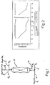
- the hydrogenation catalyst showed excellent regeneration in activity as shown in FIG. 2.
- Example 1 The catalyst of Example 1 was subjected to the same hydrogenation reaction conditions and feedstock as described in Example 1, but the regeneration process was started when the hydrogenation catalyst illustrated a diolefin hydrogenation activity of about 30% and nitrile hydrogenation activity which was almost totally deactivated, after 220 hours of operation.
- the catalyst so deactivated was regenerated according to the present invention as described in Example 1.
- FIG. 3 illustrates the excellent regeneration of the catalyst even after such extreme deactivation and contamination over in excess of 200 hours of operation.
- Example 2 The same catalyst as set forth in Example 1 was again subjected to the feedstock and hydrogenation reaction as described in Example 1.
- a hydrogen treatment was started without an initial nitrogen flushing so as to remove naphtha and other hydrocarbons from the catalyst bed.
- FIG. 4 illustrates the initial operation, Regeneration No. 1 in accordance with Example 2, and the subsequent Regeneration No. 2 using only hydrogen as described above.
- regeneration using hydrogen only, without an initial nitrogen flushing did not regenerate the hydrogenation catalyst.
- the nitrogen flushing step of the process of the present invention serves advantageously to provide excellent regeneration of a hydrogenation catalyst in accordance with the invention.
Landscapes
- Chemical & Material Sciences (AREA)
- Engineering & Computer Science (AREA)
- Chemical Kinetics & Catalysis (AREA)
- Organic Chemistry (AREA)
- Oil, Petroleum & Natural Gas (AREA)
- Materials Engineering (AREA)
- General Chemical & Material Sciences (AREA)
- Organic Low-Molecular-Weight Compounds And Preparation Thereof (AREA)
- Catalysts (AREA)
- Low-Molecular Organic Synthesis Reactions Using Catalysts (AREA)
- Production Of Liquid Hydrocarbon Mixture For Refining Petroleum (AREA)
Applications Claiming Priority (2)
| Application Number | Priority Date | Filing Date | Title |
|---|---|---|---|
| US08/934,030 US5877364A (en) | 1994-12-13 | 1997-09-19 | Process for the simultaneous selective hydrogenation of diolefins and nitriles in multiple reactor units |
| US934030 | 1997-09-19 |
Publications (3)
| Publication Number | Publication Date |
|---|---|
| EP0903394A2 true EP0903394A2 (fr) | 1999-03-24 |
| EP0903394A3 EP0903394A3 (fr) | 1999-03-31 |
| EP0903394B1 EP0903394B1 (fr) | 2003-01-02 |
Family
ID=25464839
Family Applications (1)
| Application Number | Title | Priority Date | Filing Date |
|---|---|---|---|
| EP98117746A Expired - Lifetime EP0903394B1 (fr) | 1997-09-19 | 1998-09-18 | Procédé pour l'hydrogénation simultanée de dioléfines et de nitriles dans plusieurs unités de réacteur |
Country Status (5)
| Country | Link |
|---|---|
| US (1) | US5877364A (fr) |
| EP (1) | EP0903394B1 (fr) |
| BR (1) | BR9803489A (fr) |
| DE (1) | DE69810407T2 (fr) |
| ES (1) | ES2190022T3 (fr) |
Families Citing this family (6)
| Publication number | Priority date | Publication date | Assignee | Title |
|---|---|---|---|---|
| WO2002051548A1 (fr) * | 2000-12-22 | 2002-07-04 | Eurecat Sa | Procede de regeneration de catalyseurs heterogenes et d'adsorbants |
| WO2006125832A1 (fr) | 2005-05-23 | 2006-11-30 | Repsol Ypf | Catalyseur a base de nickel et son procede d'obtention et d'utilisation |
| US8598060B2 (en) | 2006-07-31 | 2013-12-03 | Basf Se | Method of regenerating ruthenium catalysts for the ring hydrogenation of phthalates |
| US8350106B2 (en) * | 2008-06-30 | 2013-01-08 | Uop Llc | Selective hydrogenation of unsaturated aliphatic hydrocarbons in predominantly aromatic streams |
| CN102159532B (zh) | 2008-09-08 | 2014-09-17 | 三菱瓦斯化学株式会社 | 苯二甲胺的制备方法 |
| FR2984915B1 (fr) * | 2011-12-22 | 2016-07-15 | Ifp Energies Now | Procede d'hydrogenation selective de charges olefiniques avec des reacteurs permutables incluant au moins une etape de court-circuitage d'un reacteur |
Family Cites Families (5)
| Publication number | Priority date | Publication date | Assignee | Title |
|---|---|---|---|---|
| US4683052A (en) * | 1985-06-11 | 1987-07-28 | Mobil Oil Corporation | Method for non-oxidative hydrogen reactivation of zeolite dewaxing catalysts |
| DD273783A1 (de) * | 1988-07-06 | 1989-11-29 | Leuna Werke Veb | Verfahren zur in-situ-reaktivierung von pd-haltigen hydrierkatalysatoren |
| US5332705A (en) * | 1992-06-19 | 1994-07-26 | Exxon Chemical Patents Inc. | Regeneration of acetylene converter catalysts by hydrogen stripping |
| US5523271A (en) * | 1994-12-13 | 1996-06-04 | Intevep, S.A. | Catalyst for the simultaneous selective hydrogenation of diolefins and nitriles and method of making same |
| US5817589A (en) * | 1996-04-02 | 1998-10-06 | Intevep, S.A. | Regeneration of catalyst comprising flushing with inert gas followed by flushing with hydrogen |
-
1997
- 1997-09-19 US US08/934,030 patent/US5877364A/en not_active Expired - Lifetime
-
1998
- 1998-09-18 EP EP98117746A patent/EP0903394B1/fr not_active Expired - Lifetime
- 1998-09-18 BR BR9803489-8A patent/BR9803489A/pt not_active IP Right Cessation
- 1998-09-18 DE DE69810407T patent/DE69810407T2/de not_active Expired - Lifetime
- 1998-09-18 ES ES98117746T patent/ES2190022T3/es not_active Expired - Lifetime
Also Published As
| Publication number | Publication date |
|---|---|
| DE69810407T2 (de) | 2003-10-30 |
| ES2190022T3 (es) | 2003-07-16 |
| US5877364A (en) | 1999-03-02 |
| EP0903394B1 (fr) | 2003-01-02 |
| BR9803489A (pt) | 1999-12-07 |
| EP0903394A3 (fr) | 1999-03-31 |
| DE69810407D1 (de) | 2003-02-06 |
Similar Documents
| Publication | Publication Date | Title |
|---|---|---|
| US5817589A (en) | Regeneration of catalyst comprising flushing with inert gas followed by flushing with hydrogen | |
| JP2984946B2 (ja) | 石油残渣または重油を精製し、かつこれより軽質なフラクションに転換するための石油残渣または重油の水素化処理方法 | |
| JP3729621B2 (ja) | 接触分解ガソリンの水素化脱硫方法及びガソリン | |
| JP4074667B2 (ja) | 単一反応槽における多段水素処理方法 | |
| AU676844B2 (en) | Regeneration of acetylene converter catalysts by hydrogen stripping | |
| JP4961093B2 (ja) | メルカプタンを除去するための接触ストリッピング | |
| JP2010174247A (ja) | ナフサ脱硫を増大するためのcoの低減 | |
| EP0903394B1 (fr) | Procédé pour l'hydrogénation simultanée de dioléfines et de nitriles dans plusieurs unités de réacteur | |
| EP0766723B1 (fr) | Procede de reformation de charges d'hydrocarbures sur un catalyseur sensible au soufre | |
| US2770578A (en) | Saturating of a hydrocarbon fraction with hydrogen and then hydrodesulfurizing said fraction | |
| US4752595A (en) | Catalyst pretreatment for regenerated noble metal on zeolite catalyst | |
| EP0255754B1 (fr) | Méthode d'hydrogénation des oléfines | |
| CA1331864C (fr) | Procede pour l'hydrotraitement de distillat olefinque | |
| US20080029435A1 (en) | Rejuvenation process for olefin polymerization and alkylation catalyst | |
| EP0550150A1 (fr) | Méthode pour maintenir ou retrouver l'activité des catalyseurs d'hydroisomérisation | |
| AU678553B2 (en) | Acetylene converter moderators | |
| MXPA98007588A (en) | Process for the simultaneous selective hydrogenation of diolephins and nitrile in reactormultip units | |
| EP1256559A1 (fr) | Procédé et dispositif pour la purification d'une charge de styrène mettant en oeuvre un catalyseur à basse teneur en palladium | |
| US4853103A (en) | Lube catalytic dewaxing-hydrotreating process | |
| RU2117029C1 (ru) | Способ очистки продуктов каталитического риформинга от олефиновых углеводородов |
Legal Events
| Date | Code | Title | Description |
|---|---|---|---|
| PUAI | Public reference made under article 153(3) epc to a published international application that has entered the european phase |
Free format text: ORIGINAL CODE: 0009012 |
|
| PUAL | Search report despatched |
Free format text: ORIGINAL CODE: 0009013 |
|
| AK | Designated contracting states |
Kind code of ref document: A2 Designated state(s): DE ES FI FR GB IT NL |
|
| AX | Request for extension of the european patent |
Free format text: AL;LT;LV;MK;RO;SI |
|
| AK | Designated contracting states |
Kind code of ref document: A3 Designated state(s): AT BE CH CY DE DK ES FI FR GB GR IE IT LI LU MC NL PT SE |
|
| AX | Request for extension of the european patent |
Free format text: AL;LT;LV;MK;RO;SI |
|
| RHK1 | Main classification (correction) |
Ipc: C10G 45/34 |
|
| 17P | Request for examination filed |
Effective date: 19990807 |
|
| AKX | Designation fees paid |
Free format text: DE ES FI FR GB IT NL |
|
| 17Q | First examination report despatched |
Effective date: 20011031 |
|
| GRAG | Despatch of communication of intention to grant |
Free format text: ORIGINAL CODE: EPIDOS AGRA |
|
| RIC1 | Information provided on ipc code assigned before grant |
Free format text: 7C 10G 45/34 A |
|
| GRAG | Despatch of communication of intention to grant |
Free format text: ORIGINAL CODE: EPIDOS AGRA |
|
| GRAH | Despatch of communication of intention to grant a patent |
Free format text: ORIGINAL CODE: EPIDOS IGRA |
|
| GRAH | Despatch of communication of intention to grant a patent |
Free format text: ORIGINAL CODE: EPIDOS IGRA |
|
| GRAA | (expected) grant |
Free format text: ORIGINAL CODE: 0009210 |
|
| AK | Designated contracting states |
Kind code of ref document: B1 Designated state(s): DE ES FI FR GB IT NL |
|
| REG | Reference to a national code |
Ref country code: GB Ref legal event code: FG4D Free format text: 20030102 |
|
| REF | Corresponds to: |
Ref document number: 69810407 Country of ref document: DE Date of ref document: 20030206 Kind code of ref document: P |
|
| REG | Reference to a national code |
Ref country code: ES Ref legal event code: FG2A Ref document number: 2190022 Country of ref document: ES Kind code of ref document: T3 |
|
| ET | Fr: translation filed | ||
| PLBE | No opposition filed within time limit |
Free format text: ORIGINAL CODE: 0009261 |
|
| STAA | Information on the status of an ep patent application or granted ep patent |
Free format text: STATUS: NO OPPOSITION FILED WITHIN TIME LIMIT |
|
| 26N | No opposition filed |
Effective date: 20031003 |
|
| REG | Reference to a national code |
Ref country code: FR Ref legal event code: PLFP Year of fee payment: 18 |
|
| PGFP | Annual fee paid to national office [announced via postgrant information from national office to epo] |
Ref country code: FI Payment date: 20150929 Year of fee payment: 18 Ref country code: ES Payment date: 20150928 Year of fee payment: 18 Ref country code: GB Payment date: 20150928 Year of fee payment: 18 |
|
| PGFP | Annual fee paid to national office [announced via postgrant information from national office to epo] |
Ref country code: FR Payment date: 20150917 Year of fee payment: 18 |
|
| PGFP | Annual fee paid to national office [announced via postgrant information from national office to epo] |
Ref country code: IT Payment date: 20150923 Year of fee payment: 18 |
|
| PGFP | Annual fee paid to national office [announced via postgrant information from national office to epo] |
Ref country code: DE Payment date: 20150929 Year of fee payment: 18 |
|
| PGFP | Annual fee paid to national office [announced via postgrant information from national office to epo] |
Ref country code: NL Payment date: 20150926 Year of fee payment: 18 |
|
| REG | Reference to a national code |
Ref country code: DE Ref legal event code: R119 Ref document number: 69810407 Country of ref document: DE |
|
| PG25 | Lapsed in a contracting state [announced via postgrant information from national office to epo] |
Ref country code: FI Free format text: LAPSE BECAUSE OF NON-PAYMENT OF DUE FEES Effective date: 20160918 |
|
| REG | Reference to a national code |
Ref country code: NL Ref legal event code: MM Effective date: 20161001 |
|
| GBPC | Gb: european patent ceased through non-payment of renewal fee |
Effective date: 20160918 |
|
| PG25 | Lapsed in a contracting state [announced via postgrant information from national office to epo] |
Ref country code: NL Free format text: LAPSE BECAUSE OF NON-PAYMENT OF DUE FEES Effective date: 20161001 |
|
| REG | Reference to a national code |
Ref country code: FR Ref legal event code: ST Effective date: 20170531 |
|
| PG25 | Lapsed in a contracting state [announced via postgrant information from national office to epo] |
Ref country code: FR Free format text: LAPSE BECAUSE OF NON-PAYMENT OF DUE FEES Effective date: 20160930 Ref country code: DE Free format text: LAPSE BECAUSE OF NON-PAYMENT OF DUE FEES Effective date: 20170401 Ref country code: GB Free format text: LAPSE BECAUSE OF NON-PAYMENT OF DUE FEES Effective date: 20160918 |
|
| PG25 | Lapsed in a contracting state [announced via postgrant information from national office to epo] |
Ref country code: IT Free format text: LAPSE BECAUSE OF NON-PAYMENT OF DUE FEES Effective date: 20160918 |
|
| REG | Reference to a national code |
Ref country code: ES Ref legal event code: FD2A Effective date: 20180507 |
|
| PG25 | Lapsed in a contracting state [announced via postgrant information from national office to epo] |
Ref country code: ES Free format text: LAPSE BECAUSE OF NON-PAYMENT OF DUE FEES Effective date: 20160919 |