EP0903325B1 - Verfahren zur Behandlung von Klärschlamm mit Ozon - Google Patents
Verfahren zur Behandlung von Klärschlamm mit Ozon Download PDFInfo
- Publication number
- EP0903325B1 EP0903325B1 EP19980307445 EP98307445A EP0903325B1 EP 0903325 B1 EP0903325 B1 EP 0903325B1 EP 19980307445 EP19980307445 EP 19980307445 EP 98307445 A EP98307445 A EP 98307445A EP 0903325 B1 EP0903325 B1 EP 0903325B1
- Authority
- EP
- European Patent Office
- Prior art keywords
- ozone
- biosludge
- reactor
- reactors
- gas
- Prior art date
- Legal status (The legal status is an assumption and is not a legal conclusion. Google has not performed a legal analysis and makes no representation as to the accuracy of the status listed.)
- Expired - Lifetime
Links
Images


Classifications
-
- C—CHEMISTRY; METALLURGY
- C02—TREATMENT OF WATER, WASTE WATER, SEWAGE, OR SLUDGE
- C02F—TREATMENT OF WATER, WASTE WATER, SEWAGE, OR SLUDGE
- C02F3/00—Biological treatment of water, waste water, or sewage
- C02F3/02—Aerobic processes
- C02F3/12—Activated sludge processes
- C02F3/1205—Particular type of activated sludge processes
- C02F3/1221—Particular type of activated sludge processes comprising treatment of the recirculated sludge
-
- C—CHEMISTRY; METALLURGY
- C02—TREATMENT OF WATER, WASTE WATER, SEWAGE, OR SLUDGE
- C02F—TREATMENT OF WATER, WASTE WATER, SEWAGE, OR SLUDGE
- C02F1/00—Treatment of water, waste water, or sewage
- C02F1/72—Treatment of water, waste water, or sewage by oxidation
- C02F1/78—Treatment of water, waste water, or sewage by oxidation with ozone
-
- Y—GENERAL TAGGING OF NEW TECHNOLOGICAL DEVELOPMENTS; GENERAL TAGGING OF CROSS-SECTIONAL TECHNOLOGIES SPANNING OVER SEVERAL SECTIONS OF THE IPC; TECHNICAL SUBJECTS COVERED BY FORMER USPC CROSS-REFERENCE ART COLLECTIONS [XRACs] AND DIGESTS
- Y02—TECHNOLOGIES OR APPLICATIONS FOR MITIGATION OR ADAPTATION AGAINST CLIMATE CHANGE
- Y02W—CLIMATE CHANGE MITIGATION TECHNOLOGIES RELATED TO WASTEWATER TREATMENT OR WASTE MANAGEMENT
- Y02W10/00—Technologies for wastewater treatment
- Y02W10/10—Biological treatment of water, waste water, or sewage
Definitions
- the present invention relates to a method for ozone-treating biosludges, such as activated sludge, digested sludge and the like, occurring in biological treatment of aqueous organic wastes and to a method for such ozone treatment.
- biosludges such as activated sludge, digested sludge and the like
- biosludges are formed, such as activated sludge and digested sludge. While excessive biosludges formed in the biological treatment system should be removed therefrom, they exhibit a high biological stability, which makes disposal of such biosludges through biodegradation or biolysis difficult. In addition, they are highly persistent to dehumidification, which makes disposal of such biosludge by having recourse to dewatering difficult.
- the method for ozone-treating excess amount of biosludge of this prior art uses an apparatus in which an ozone-containing gas is blown into a layer of a biosludge contained in an ozonizing reactor to cause a gas/liquid contact to facilitate the ozonization of the biosludge.
- the reactor used in the apparatus of the prior art is designed to be filled with the biosludge up to a liquid depth of about 1 meter or so and to blow the ozone-containing gas thereinto under atmospheric pressure, so that only a relatively low ozone concentration in the liquor can be attained for effecting the ozonization, resulting in a lower yield of ozonization.
- US-A-5013429 discloses a method for ozone-treating biosludge, comprising passing the biosludge through a plurality of reactors in series, while supplying an ozone-containing gas to each of the reactors with agitation of the biosludge, under pressure.
- An object of the present invention is to treat biosludge with ozone at a high absorption rate and under a high load, at a high efficiency of power consumption and at a high rate of reduction of the biosludge, while suppressing foaming and preventing clogging of the gas distributor.
- a method for ozone-treating biosludge comprises passing the biosludge through a plurality of reactors in series, while supplying an ozone-containing gas to each of the reactors with agitation of the biosludge, under pressure, in such a manner that there are nearly equal (within ⁇ 20%) rates of ozone absorption in all the reactors.
- the biosludges to be treated by the method according to the present invention include those which occur in an aerobic and anaerobic biological treatments of aqueous organic wastes, such as activated sludge and digested sludge, preferably those which are composed predominantly of biosludge of living microorganisms, such as the so-called excess sludge, though biosludges containing some inorganic ingredients as in the so-called coagulated or flocculated sludge may also be included.
- ozone-containing gas for example, ozonized air and ozone-containing oxygen, may be used, wherein the ozonized air produced by passing pressurized dry air through an ozone generator is preferred in general.
- the ozone treatment of the biosludges is effected by passing the ozone-containing gas through a plurality of (preferably three) ozonizing reactors in series, each charged with biosludge-containing liquor, so as to effect an intimate contact of the gas with the biosludge in each reactor.
- the ozonizing reactor may be designed so as to effect the contact of the ozone-containing gas with the biosludge by stirring the liquor using a stirrer together with the ozone-containing gas introduced thereinto under an elevated pressure to facilitate the ozone absorption and, thus, the ozonization of the biosludge.
- the ozone-containing gas may be supplied to the plurality of reactors either in a series flow or in a parallel flow.
- the stirrer may preferably be arranged within the reactor so that the rotating stirring element thereof confronts the entrance of the ozone-containing gas into the reactor.
- the pressure of the ozone-containing gas may preferably be in the range of 0.05 - 0.5 MPa (gauge), preferably 0.1 - 0.2 MPa (gauge), which may be adjusted by making use of the discharge pressure from the ozone generator and by using a pressure regulating valve disposed at the outlet of the reactor.
- the ozonizing reactors are operated so as to attain a nearly equalized (within ⁇ 20 %) ozone absorption rate for all the reactors by adjusting, for example, the reactor capacity and the stirring strength.
- ozone absorption efficiency can be increased.
- the volume of the ozone-containing gas existing in the reactor is reduced, whereby the performance of the apparatus can be increased in proportion to the internal pressure.
- the internal pressure of the reactor is 0.098 MPa (gauge)
- the volume flow rate of gas is reduced to 1/2 of that under the atmospheric pressure, so that a doubled performance of the reactor becomes possible.
- the biosludge to be ozone-treated is passed through a plurality of ozone treating reactors in series, while supplying an ozone-containing gas to each of the reactors with adjusted strength of agitation of the biosludge under a pressurized condition in such a manner that a nearly equalized ozone absorption rate is realized in all the reactors, whereby a high ozone treating efficiency and, thus, a high rate of reduction of biosludge formation can be attained.
- the ozone treatment efficiency can be increased with simultaneous increase in the power consumption efficiency.
- the reaction efficiency is, in general, lower as compared with a batch-wise ozone treatment, because the resulting ozonized biosludge is inevitably be mixed with the biosludge supplied thereto.
- the reaction efficiency can be increased by performing the ozone treatment in a so-called plug flow principle in which the ozone-containing gas is supplied to the reactor in a parallel flow with the stream of the biosludge supplied thereto.
- the ozonizing zone of the reaction system is allotted to a plurality of sections each consisting of an isolated reactor, each of which is supplied with the ozone-containing gas, whereby the integral ozonization reaction can be effected in a way quite similar to that based on the plug flow principle and, thus, an increase in the reaction efficiency can be attained.
- the supply of ozone is performed completely equally, an ideal plug flow can be simulated and the reaction efficiency can further be increased.
- an apparatus and a method for ozone-treating biosludges which can attain a high ozone absorption rate with a high ozonizing performance under suppression of foaming phenomenon without suffering from occurrence of clogging of the gas supply means can be realized according to the present invention by incorporating the inventive feature that the biosludge-containing liquor is caused to pass through a plurality of ozonizing reactors in series, while the ozone-containing gas is supplied to each of the reactors under a pressurized condition in such a manner that a nearly equalized ozone absorption rate in all the reactors will be attained.
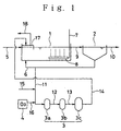
- FIG. 1 A flow sheet of an arrangement for a biological treatment of biosludges provided with the apparatus for ozone-treating the biosludge according to the present invention is shown in Fig. 1.
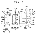
- the apparatus for ozone-treating the biosludge is shown in Fig. 2 also in a flow sheet.
- the arrangement given in Fig. 1 comprises an aeration tank 1, a settling basin 2 and an ozone treating unit 3 with an ozone generator 4.
- the aeration tank 1 is connected with an aqueous organic waste supply line 5 and a biosludge return line 6 and is provided internally with an air distributor 8 communicating to an air supply line 7.
- a line 9 connects the aeration tank 1 with the settling basin 2 to which a treated liquor discharge line 10 and the biosludge return line 6 are connected.
- the ozone treating unit 3 comprises a first, a second and a third reactor 3a, 3b and 3c.
- the first reactor is connected with a biosludge passage 11 branched from the biosludge return line 6 and the three reactors are connected in series by connection lines 12 and 13 disposed between the first and the second reactors and between the second and third reactors, respectively.
- an acid injection line 15 and an ozone injection line 16 connected to the ozone generator 4.
- the ozonized sludge transfer line 14 communicates to the aeration tank 1 via a gas/liquid separator 17 which communicates to an ozone decomposer (not shown) via a spent ozone line 18.
- an aqueous organic waste is biologically treated under an aerobic condition in the following manner.
- the aeration tank 1 is supplied with the aqueous organic waste via the waste supply line 5 and with air via the air supply line 7 through an air distributor 8, while returning the biosludge settled in the settling basin 2 to the aeration tank 1.
- the aerated liquor in the aeration tank 1 is transferred via the line 9 to the settling basin 2 where it is subjected to a solid/liquid separation.
- the separated liquor is discharged out of the treatment system via the treated liquor discharge line 10 and the separated biosludge is returned to the aeration tank 1 via the biosludge return line 6.
- the above-mentioned treatment is an ordinary aerobic biological treatment and, in general, a large amount of excess sludge is formed during the treatment.
- a part of the so-formed sludge is withdrawn from the treating system via the biosludge passage 11 and is subjected to the ozone treatment by acidifying it to a pH of 2.5 - 3.5 by introducing thereinto an acid, such as sulfuric acid or hydrochloric acid, and injecting an ozone-containing gas into the so-acidified sludge from the ozone generator 4 via the ozone injection line 16.
- the biosludge is converted by the ozone treatment into an easily biodegradable BOD component and the resulting ozone-treated mass is sent to the gas/liquid separator 17 via the ozonized sludge transfer line 14, from which the separated biosludge is guided into the aeration tank 1 and the separated spent ozone-containing gas is forwarded to an ozone decomposer via the spent ozone line 18.
- the details of the ozone treating unit 3 are shown in Fig. 2.
- the biosludge passage 11 opens into the first reactor 3a at its lower portion.
- the connection lines 12 and 13 are arranged to connect between an upper portion of the first reactor 3a and a lower portion of the second reactor 3b and between an upper portion of the second reactor 3b and a lower portion of the third reactor 3c, respectively.
- the ozonized sludge transfer line 14 is guided from an upper portion of the third reactor 3c and opens into the gas/liquid separator 17.
- Each of the first, second and third reactors 3a, 3b and 3c is provided with a stirrer 20a, 20b or 20c rotated each by a motor 23a, 23b, 23c and having each a stirring element 21a, 21b, 21c in a form of a turbine in a posture confronting the opening of biosludge passage 11 or of connection line 12, 13, respectively, and a foam destroying impeller 22a, 22b, 22c in a form of a comb at a portion near the liquid level.
- a plurality of upright baffling plates 24a, 24b and 24c are arranged at nealy an equal interval.
- the third reactor 3c has a capacity greater than those of the first and second rectors 3a and 3b.
- the third reactor is provided at its middle height a partition wall 25 to divide the reaction chamber into a plurality of sections 26a and 26b.
- the stirrer 20c has a further stirring element 21d within the section 26b above a hole 27 piercing the partition wall 25.
- those of a type of flat disc turbine having vertically directing blades may preferably be employed.
- the stirring element 21d may preferably be constituted of that of a type of pitched disc turbine having inclinedly directing blades for causing an upward flow.
- those having more blades than those of the stirring elements 21a and 21b may preferably be employed.
- Each of the reactors 3a, 3b, 3c is provided internally with a guide element 28a, 28b or 28c in a form of a half sectioned cylinder extending from above the liquid level to below it in opposition to the connection line 12 or 13 or to the ozonized sludge transfer line 14, respectively.
- the ozonized sludge transfer line 14 is provided with a ball valve 29.
- the reactors are maintained each at a pressure within the preferred range given above, by making use of the discharge pressure from the ozone generator for pressure elevation and adjusting the opening degree of the ball valve 29.
- each reactor 3a, 3b and 3c are so selected that a nearly equalized ozone absorption rate is obtained for all the reactors.
- a nearly equalized ozone absorption rate for all the reactors can be realized by designing the ozone gas transfer efficiency for a preceding reactor is lower than that for the subsequent reactor, since the ozone-containing gas is supplied to the reactors in a parallel flow with the flow of the biosludge.
- the ozone gas transfer efficiency is calculated as the quotient of 320 g O 3 /hr by 1,000 g O 3 /hr, namely 32 %.
- the integral ozone gas transfer efficiency is calculated to be 96 %.
- the biosludge to be subjected to the ozone treatment is supplied to the reactors via the biosludge passage 11 and is caused to pass through the reactors 3a, 3b and 3c in series, while injecting the ozone-containing gas from the ozone generator 4 into the biosludge passage 11.
- the contact of the ozone-containing gas with the biosludge is facilitated by operating the stirrers 20a, 20b and 20c in each reactor so as to reach a nearly equalized ozone absorption rate in all the reactors to convert the biosludge into a BOD component.
- the ozone absorption rate can be adjusted by altering the stirring strength in each reactor so as to reduce the residence time of the biosludge in each reactor before it is transferred to the subsequent reactor, so that scarce occurrence of foaming of the biosludge is possible.
- the foam destroying wings are driven into rotation. A mixed stream of the biosludge and the gas in this de-foamed state is transferred from a portion near the liquid level to the subsequent reactor via the connection line 12 (or 13).
- the third reactor 3c is designed to have a greater volume for increasing the ozone gas transfer efficiency, wherein the reactor is internally subdivided into a plurality of chambers 26a, 26b etc. by partition wall(s) 25 in order to prevent an extended residence time in each chamber.
- the stirring element 21d has blades or vanes arranged in an inclined direction and causes a lifting stream into which the biosludge will be sucked and lifted up. At around the liquid level, the gas and the liquor are guided from above and from beneath, respectively, into the guide element 28c and are delivered out via the ozonized sludge transfer line 14.
- the pressures in the reactors 3a, 3b and 3c are maintained at a pressurized state by adjusting the ball valve 29.
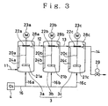
- FIG. 3 Another embodiment of the ozone treating unit is shown in Fig. 3 in a flow sheet, in which the ozone-containing gas is supplied to the reactors 3a, 3b and 3c in parallel.
- the reactors 3a, 3b and 3c are designed to have a configuration, structure and size nearly the same with each other and similar to those of the first and the second reactors 3a and 3b of Fig. 2.
- the ozone injecting lines 16a, 16b and 16c are each branched from the line 16 from the ozone generator 4 and joins to the first, second and third reactors 3a, 3b and 3c each at a lower position thereof.
- connection lines 12 and 13 connects between an upper portion of the first reactor 3a and an upper portion of the second reactor 3b and between an upper portion of the second reactor 3b and an upper portion of the third reactor 3c, respectively.
- the guide elements 28a, 28b and 28c are arranged each in opposition to the connection line 12, to the connection line 13 and to the ozonized sludge transfer line 14, respectively.
- all the reactors 3a, 3b and 3c For attaining a nearly equalized ozone absorption rate for all the reactors 3a, 3b and 3c by supplying them each with nearly the same amount of the ozone-containing gas in the above-described embodiment of the unit, all the reactors have the same design and are operated under the same conditions so as to attain a nearly equalized ozone absorption rate.
- each reactor is operated to attain an absorption of 1/3 of the ozone, namely, 320 g O 3 /hr.
- the reactors are designed in their capacities and operation conditions so that a gas transfer efficiency of 90 % or higher should be reached in each reactor.
- the biosludge is supplied to the first reactor 3a via the biosludge passage 11 and is caused to pass through the second and third reactors 3b and 3c, whereupon it is withdrawn from the unit via the ozonized sludge transfer line 14 through the ball valve 29, while introducing the ozone-containing gas through the ozone injection lines 16a, 16b and 16c into the reactors each at a lower position thereof and while driving each stirrer 20a, 20b, 20c to effect contact of the ozone-containing gas with the biosludge.
- the ozone absorption rate in all the reactors is settled at nearly the same level, wherein the unreacted ozone gas remaining in a preceding reactor is transferred together with the biosludge to the subsequent reactor, where they are further brought into contact with each other to further progress the ozone absorption.
- the guide elements 28a, 28b and 28c serve for guiding the gas and the liquor from above and from beneath, respectively, and for preventing a possible short circuit of the newly introduced biosludge.
- the unit of Fig. 3 may preferably be employed in case the amount of the gas is small and the ozone generating cost can be disregarded.
- the unit of Fig. 2 may preferably be employed in case the ozone generation cost should be regarded as important.
- the ozone-containing gas can be supplied only by means of the ozone injection lines 16, 16a, 16b and 16c without having recourse to any gas distributor or perforated plate, so that any possibility of clogging of ozone injection means is avoided.
- the first and the second reactors 3a and 3b have the same capacity of 200 liters and the third reactor 3c has a capacity of 800 liters.
- Each reactor is provided internally with four baffling plates (24a, 24b or 24c).
- disc turbines are employed for the stirring elements (21a, 21b, 21c, 21d).
- the biosludge and the gas flow through the reactors from the biosludge passage 11 and via the connection lines 12 and 13.
- the biosludge and the gas are introduced into each reactor at a position just below the stirring element (21a, 21b, 21c).
- the rotational frequencies of the stirring elements 21a, 21b, 21c and 21d can be altered in a range from zero to about 120 % by means of an inverter.
- each a four vane flat disc turbine is employed for the stirring elements 21a and 21b.
- the third reactor is subdivided internally at a middle height thereof into two piled chambers by a partition wall in order to settle the theoretical plate number of at least one.
- the stirring element 21c in the lower chamber consists of a 6 vane flat disc turbine and the stirring element 21d in the upper chamber consists of a 6 vane pitched disc turbine.
- each reactor of the ozone treatment unit of this experiment is provided internally at the position near the liquid level with a comb-shaped foam destroying impeller (22a, 22b, 22c) in order to avoid decrease in the biosludge concentration in the reactors.
- the foam destroying impeller is arranged so that its terminal end is submerged about 20 mm below the liquid level and driven to rotate so as to destroy foams on the liquid surface.
- a half cut guide elements 28c is arranged in a vertical posture in front of the reactor exit.
- the lower half of the guide element is held submerged in the liquid and the biosludge and the gas are guided thereinto from above and from below, respectively, and are then discharged out.
- Example 1 the total power consumption for operating the reactors at an ozone-containing gas supply rate of 30 Nm 3 /hr and at an ozone gas transfer efficiency of 95 % was found to be 6 kWH. In contrast, the corresponding power consumption for operating the unit of Comparative Example 1 under the same condition was found to be 12 - 15 kWH. Thus, an increase in the power consumption efficiency amounting to at least two times that of the Comparative Example 1 is obtained by the apparatus and method according to the present invention.
- the numerical value 0.35 is the yield of biosludge per influent BOD.
- the values for the amount of ozone-treated biosludge per day were determined by the arithmetic product of the amount of biosludge to be treated as given in Table 3 and the biosludge concentration.
- the amounts of biosludge were calculated cumulatively over the experiment period to determine the eliminated amount of biosludge and the amount of treated biosludge during the experimental period.
- the experimental results are shown in Fig. 5 in a relationship between the number of reactors and the amount of treated biosludge required for the biosludge elimination.
- the amount of treated biosludge requisite for the biosludge elimination is decreased as the number of reactors is reduced, even though the amount of ozone dosage is the same for all the runs.
- 6.1 tons of biosludge were required to be ozone-treated.
- the number of reactors was increased to three, only 3.3 tons of biosludge were required to be ozone-treated for attaining an elimination of 1 ton of biosludge.
- the amount of ozone-treated biosludge required for reducing unit amount of the biosludge is in the order (run 5)>(run 6)>(run 7).
- a larger amount of ozone was absorbed in the first reactor, a larger amount of biosludge to be treated was required for the biosludge elimination. While the reason therefor is not clear, it is believed that biosludge with lower degree of ozonization may be shortcircuited from preceding reactor, since each reactor is a complete mixing type.
- the amount of ozone reacted in the reactor was equalized for all the reactors, the reaction proceeds in a so-called plug flow principle. In this case, a reduction of biosludge can be expected, since a large amount of a biosludge mixture having lower ozonization degree may not be exhausted from any reactor.
Landscapes
- Life Sciences & Earth Sciences (AREA)
- Hydrology & Water Resources (AREA)
- Engineering & Computer Science (AREA)
- Environmental & Geological Engineering (AREA)
- Water Supply & Treatment (AREA)
- Chemical & Material Sciences (AREA)
- Organic Chemistry (AREA)
- Biodiversity & Conservation Biology (AREA)
- Microbiology (AREA)
- Treatment Of Sludge (AREA)
- Treatment Of Water By Oxidation Or Reduction (AREA)
- Processing Of Solid Wastes (AREA)
Claims (7)
- Verfahren zur Ozonbehandlung von Bioschlamm umfassend das Hindurchleiten des Bioschlamms durch eine Mehrheit von Reaktoren (3a, 3b, 3c) in Reihe, während ein Ozon enthaltendes Gas zu jedem der Reaktoren unter Bewegung des Bioschlamms unter Druck in einer solchen Weise zugeführt wird, dass es nahezu die gleichen (innerhalb ± 20%) Ozon-Absorptionsraten in allen Reaktoren gibt.
- Verfahren wie in Anspruch 1 beansprucht, worin drei Reaktoren eingesetzt werden.
- Verfahren wie in Anspruch 2 beansprucht, worin das Ozon enthaltende Gas den drei Reaktoren zugeführt wird, indem man das Gas durch sie in Reihe strömen lässt.
- Verfahren wie in Anspruch 2 beansprucht, worin das Ozon enthaltende Gas den drei Reaktoren parallel zugeführt wird.
- Verfahren wie in irgendeinem vorhergehenden Anspruch beansprucht, worin der Bioschlamm von einem oberen Teil eines ersten Reaktors (3a) zu einem unteren Teil eines zweiten Reaktors (3b) und von einem oberen Teil des zweiten Reaktors zu einem unteren Teil eines dritten Reaktors (3c) geleitet wird.
- Verfahren nach irgendeinem vorhergehenden Anspruch, worin der Bioschlamm durch einen Rührer (21a, 21b, 21c) bewegt wird, der um eine vertikale Achse rotiert.
- Verfahren zur Behandlung von wässrigem organischem Abfall, welches umfasst das Belüften des Abfalls in Anwesenheit von aktiviertem Bioschlamm, das Absetzen des Bioschlamms von dem belüfteten Abfall und das Behandeln eines Teils des Bioschlamms durch ein Verfahren nach irgendeinem der Ansprüche 1 bis 6.
Applications Claiming Priority (3)
| Application Number | Priority Date | Filing Date | Title |
|---|---|---|---|
| JP255598/97 | 1997-09-19 | ||
| JP25559897 | 1997-09-19 | ||
| JP25559897A JP3397096B2 (ja) | 1997-09-19 | 1997-09-19 | 生物汚泥のオゾン処理装置および方法 |
Publications (2)
| Publication Number | Publication Date |
|---|---|
| EP0903325A1 EP0903325A1 (de) | 1999-03-24 |
| EP0903325B1 true EP0903325B1 (de) | 2003-01-15 |
Family
ID=17280958
Family Applications (1)
| Application Number | Title | Priority Date | Filing Date |
|---|---|---|---|
| EP19980307445 Expired - Lifetime EP0903325B1 (de) | 1997-09-19 | 1998-09-15 | Verfahren zur Behandlung von Klärschlamm mit Ozon |
Country Status (6)
| Country | Link |
|---|---|
| US (2) | US6146521A (de) |
| EP (1) | EP0903325B1 (de) |
| JP (1) | JP3397096B2 (de) |
| DE (1) | DE69810722T2 (de) |
| DK (1) | DK0903325T3 (de) |
| MY (2) | MY127772A (de) |
Cited By (2)
| Publication number | Priority date | Publication date | Assignee | Title |
|---|---|---|---|---|
| US7309432B1 (en) | 2006-09-29 | 2007-12-18 | Praxair Technology, Inc. | System and method for eliminating sludge via ozonation |
| US9738549B2 (en) | 2011-12-01 | 2017-08-22 | Praxair Technology, Inc. | Method for sludge ozonation in a wastewater treatment system |
Families Citing this family (18)
| Publication number | Priority date | Publication date | Assignee | Title |
|---|---|---|---|---|
| DE19920010A1 (de) * | 1999-05-03 | 2000-11-16 | Philaqua Aufbereitungstechnik | Verfahren zur aeroben biologischen Behandlung von Faulschlämmen |
| DE19942184A1 (de) * | 1999-09-03 | 2001-03-15 | Messer Griesheim Gmbh | Verfahren zur Behandlung von Abwasser in einer biologischen Kläranlage und dafür geeignete Vorrichtung |
| FR2801880B1 (fr) * | 1999-12-07 | 2002-02-22 | Degremont | Procede et installation de traitement d'eaux residuaires comprenant un traitement additionnel des boues par ozonation |
| JP4608726B2 (ja) * | 2000-04-06 | 2011-01-12 | 栗田工業株式会社 | 生物処理装置 |
| JP4622057B2 (ja) * | 2000-07-05 | 2011-02-02 | 日本下水道事業団 | 有機性排液の処理方法 |
| JP4593175B2 (ja) | 2004-01-07 | 2010-12-08 | 三菱電機株式会社 | 汚泥処理方法および汚泥処理装置 |
| US20080078719A1 (en) * | 2006-09-29 | 2008-04-03 | Malcolm Ezekiel Fabiyi | System and method for treating wastewater |
| US7513999B2 (en) * | 2006-09-29 | 2009-04-07 | Praxair Technology, Inc. | Ozonation of wastewater for reduction of sludge or foam and bulking control |
| WO2009028481A1 (ja) | 2007-08-28 | 2009-03-05 | Diamond Engineering Co., Ltd. | 活性汚泥資材、生物反応槽内の余剰汚泥の減量方法、及び生物反応槽の維持管理方法 |
| DE102010041582A1 (de) | 2010-09-29 | 2012-03-29 | Siemens Aktiengesellschaft | Kombiniertes Verfahren zur Desinfektion, Verfahren zur Aufbereitung von Schlämmen |
| CN106103361A (zh) * | 2014-04-29 | 2016-11-09 | 三菱电机株式会社 | 污泥处理装置和污泥处理方法 |
| US9975794B2 (en) * | 2014-06-16 | 2018-05-22 | EnviroPure Systems LLC | Managing greywater from a microbial decomposition process |
| CN107311422A (zh) * | 2017-08-11 | 2017-11-03 | 江苏浦坤纳米科技有限公司 | 一种污泥减量化反应系统及处理方法 |
| CN109574446A (zh) * | 2018-12-14 | 2019-04-05 | 上海交通大学 | 一种利用臭氧/混凝剂/疏水性聚氨酯改善污泥脱水性能的方法 |
| CN110482679A (zh) * | 2019-07-30 | 2019-11-22 | 张家港市大新污水处理有限公司 | 一种用于污水处理水解酸化反应池 |
| JP7462527B2 (ja) * | 2020-10-06 | 2024-04-05 | 三菱電機株式会社 | 下水汚泥処理装置および下水汚泥処理方法 |
| CN115784549A (zh) * | 2022-12-19 | 2023-03-14 | 北京恩菲环保技术有限公司 | 一种两段式微纳米臭氧氧化污泥处理系统与方法 |
| IT202300023256A1 (it) * | 2023-11-06 | 2025-05-06 | Dario Tufoni | Impianto di rigenerazione di fanghi senza aggiunta di acqua e metodo ad esso associato |
Family Cites Families (10)
| Publication number | Priority date | Publication date | Assignee | Title |
|---|---|---|---|---|
| US4250040A (en) * | 1978-07-19 | 1981-02-10 | Laraus Julius | Method for purifying septic tank effluent |
| JPS59225795A (ja) * | 1983-06-06 | 1984-12-18 | Ebara Infilco Co Ltd | 有機性廃水の生物処理方法 |
| JPS59109289A (ja) * | 1983-11-28 | 1984-06-23 | Toshiba Corp | 廃水処理装置 |
| US4582612A (en) * | 1983-12-09 | 1986-04-15 | Long Enterprises, Inc. | Sewage sludge treatment apparatus |
| US4695388A (en) * | 1984-09-14 | 1987-09-22 | Long Enterprises, Inc. | Apparatus and process for rapid sewage sludge separation |
| US5013429A (en) * | 1989-03-08 | 1991-05-07 | Lenox Institute For Research, Inc. | Apparatus for stabilizing sludge |
| US5145582A (en) * | 1989-03-08 | 1992-09-08 | Lenox Institute For Research, Inc. | Method for stabilizing sludge |
| US5217617A (en) * | 1991-12-17 | 1993-06-08 | Baker Hughes Incorporated | Multi-cell transportable bioslurry reactor |
| JP3180418B2 (ja) * | 1992-03-26 | 2001-06-25 | 株式会社明電舎 | 汚泥処理工程における返流水処理装置 |
| EP0736495A3 (de) * | 1995-04-04 | 1998-01-14 | N.V. Kema | Verfahren und Vorrichtung zur Schlammbehandlung |
-
1997
- 1997-09-19 JP JP25559897A patent/JP3397096B2/ja not_active Expired - Fee Related
-
1998
- 1998-09-15 DE DE69810722T patent/DE69810722T2/de not_active Expired - Lifetime
- 1998-09-15 EP EP19980307445 patent/EP0903325B1/de not_active Expired - Lifetime
- 1998-09-15 DK DK98307445T patent/DK0903325T3/da active
- 1998-09-16 US US09/154,427 patent/US6146521A/en not_active Expired - Lifetime
- 1998-09-17 MY MYPI0302806 patent/MY127772A/en unknown
- 1998-09-17 MY MYPI9804274 patent/MY118721A/en unknown
-
2000
- 2000-07-18 US US09/618,226 patent/US6592767B1/en not_active Expired - Fee Related
Cited By (3)
| Publication number | Priority date | Publication date | Assignee | Title |
|---|---|---|---|---|
| US7309432B1 (en) | 2006-09-29 | 2007-12-18 | Praxair Technology, Inc. | System and method for eliminating sludge via ozonation |
| US7695622B2 (en) | 2006-09-29 | 2010-04-13 | Praxair Technology, Inc. | System and method for eliminating sludge via ozonation |
| US9738549B2 (en) | 2011-12-01 | 2017-08-22 | Praxair Technology, Inc. | Method for sludge ozonation in a wastewater treatment system |
Also Published As
| Publication number | Publication date |
|---|---|
| DE69810722D1 (de) | 2003-02-20 |
| US6592767B1 (en) | 2003-07-15 |
| JPH1190496A (ja) | 1999-04-06 |
| MY127772A (en) | 2006-12-29 |
| DK0903325T3 (da) | 2003-05-05 |
| EP0903325A1 (de) | 1999-03-24 |
| DE69810722T2 (de) | 2003-11-13 |
| MY118721A (en) | 2005-01-31 |
| US6146521A (en) | 2000-11-14 |
| JP3397096B2 (ja) | 2003-04-14 |
Similar Documents
| Publication | Publication Date | Title |
|---|---|---|
| EP0903325B1 (de) | Verfahren zur Behandlung von Klärschlamm mit Ozon | |
| US7695622B2 (en) | System and method for eliminating sludge via ozonation | |
| US4337152A (en) | Aeration apparatus and method | |
| EP0881195B1 (de) | Methode und vorrichtung zur biologischen behandlung von organisch belastetem abwasser | |
| JP4509373B2 (ja) | オゾン処理による付加的な汚泥処理を備えた廃水の浄化方法及びその装置 | |
| EP1976804A1 (de) | Ozonierung von abwasser zur minderung von schlamm- oder schaumbildung und zur vermehrungssteuerung | |
| EP1905744A1 (de) | System und Verfahren zur Behandlung von Abwasser | |
| US4136023A (en) | Methods and apparatus for treating wastewater | |
| EP0261822A2 (de) | Behandlung von wässerigem Abfall | |
| US4206047A (en) | Multi-stage systems for waste water oxidation | |
| US7497949B2 (en) | System and method for oxygenating an aerobic sludge digester | |
| US4451373A (en) | Ring channel aeration apparatus and method | |
| CN208218632U (zh) | 一种填料式变气压强化剩余污泥臭氧减量化装置 | |
| CN113060827B (zh) | 一种好氧生物处理的反应装置 | |
| US3207313A (en) | Apparatus for aeration of waste products | |
| CN119241003A (zh) | 一种顺酐污水处理工艺及污水处理系统 | |
| JP7462527B2 (ja) | 下水汚泥処理装置および下水汚泥処理方法 | |
| IL45829A (en) | Method and apparatus for oxygenating wastewater | |
| JPH01123697A (ja) | 有機性廃水の好気性生物処理装置 | |
| CN210945291U (zh) | 用于污泥减量化处理的系统 | |
| CN115259449A (zh) | 一种自调酸度的多相催化氧化深度处理废水的工艺 | |
| EP1020409A1 (de) | System zur Abwasserbehandlung | |
| WO1998034880A1 (en) | Integrated wastewater treatment system with induced sludge velocity | |
| CN114180723B (zh) | 一种强化曝气的好氧生物流化床污水处理工艺和装置 | |
| JPH10263583A (ja) | 活性汚泥処理装置及び処理方法 |
Legal Events
| Date | Code | Title | Description |
|---|---|---|---|
| PUAI | Public reference made under article 153(3) epc to a published international application that has entered the european phase |
Free format text: ORIGINAL CODE: 0009012 |
|
| AK | Designated contracting states |
Kind code of ref document: A1 Designated state(s): DE DK FR GB IT NL |
|
| AX | Request for extension of the european patent |
Free format text: AL;LT;LV;MK;RO;SI |
|
| 17P | Request for examination filed |
Effective date: 19990906 |
|
| R17P | Request for examination filed (corrected) |
Effective date: 19990906 |
|
| AKX | Designation fees paid |
Free format text: DE DK FR GB IT NL |
|
| 17Q | First examination report despatched |
Effective date: 20000428 |
|
| GRAG | Despatch of communication of intention to grant |
Free format text: ORIGINAL CODE: EPIDOS AGRA |
|
| RTI1 | Title (correction) |
Free format text: METHOD FOR OZONE TREATMENT OF SEWAGE SLUDGE |
|
| GRAG | Despatch of communication of intention to grant |
Free format text: ORIGINAL CODE: EPIDOS AGRA |
|
| GRAH | Despatch of communication of intention to grant a patent |
Free format text: ORIGINAL CODE: EPIDOS IGRA |
|
| GRAH | Despatch of communication of intention to grant a patent |
Free format text: ORIGINAL CODE: EPIDOS IGRA |
|
| GRAA | (expected) grant |
Free format text: ORIGINAL CODE: 0009210 |
|
| AK | Designated contracting states |
Kind code of ref document: B1 Designated state(s): DE DK FR GB IT NL |
|
| REG | Reference to a national code |
Ref country code: GB Ref legal event code: FG4D |
|
| REF | Corresponds to: |
Ref document number: 69810722 Country of ref document: DE Date of ref document: 20030220 Kind code of ref document: P |
|
| REG | Reference to a national code |
Ref country code: DK Ref legal event code: T3 |
|
| ET | Fr: translation filed | ||
| PLBE | No opposition filed within time limit |
Free format text: ORIGINAL CODE: 0009261 |
|
| STAA | Information on the status of an ep patent application or granted ep patent |
Free format text: STATUS: NO OPPOSITION FILED WITHIN TIME LIMIT |
|
| 26N | No opposition filed |
Effective date: 20031016 |
|
| PGFP | Annual fee paid to national office [announced via postgrant information from national office to epo] |
Ref country code: DK Payment date: 20110912 Year of fee payment: 14 |
|
| PGFP | Annual fee paid to national office [announced via postgrant information from national office to epo] |
Ref country code: GB Payment date: 20120912 Year of fee payment: 15 |
|
| PGFP | Annual fee paid to national office [announced via postgrant information from national office to epo] |
Ref country code: DE Payment date: 20120912 Year of fee payment: 15 Ref country code: FR Payment date: 20120926 Year of fee payment: 15 Ref country code: IT Payment date: 20120914 Year of fee payment: 15 |
|
| PGFP | Annual fee paid to national office [announced via postgrant information from national office to epo] |
Ref country code: NL Payment date: 20120919 Year of fee payment: 15 |
|
| REG | Reference to a national code |
Ref country code: DE Ref legal event code: R082 Ref document number: 69810722 Country of ref document: DE Representative=s name: MEISSNER, BOLTE & PARTNER GBR, DE |
|
| REG | Reference to a national code |
Ref country code: DE Ref legal event code: R082 Ref document number: 69810722 Country of ref document: DE Representative=s name: MEISSNER, BOLTE & PARTNER GBR, DE |
|
| REG | Reference to a national code |
Ref country code: NL Ref legal event code: V1 Effective date: 20140401 |
|
| REG | Reference to a national code |
Ref country code: DK Ref legal event code: EBP Effective date: 20130930 |
|
| GBPC | Gb: european patent ceased through non-payment of renewal fee |
Effective date: 20130915 |
|
| REG | Reference to a national code |
Ref country code: DE Ref legal event code: R119 Ref document number: 69810722 Country of ref document: DE Effective date: 20140401 |
|
| REG | Reference to a national code |
Ref country code: FR Ref legal event code: ST Effective date: 20140530 |
|
| PG25 | Lapsed in a contracting state [announced via postgrant information from national office to epo] |
Ref country code: GB Free format text: LAPSE BECAUSE OF NON-PAYMENT OF DUE FEES Effective date: 20130915 |
|
| PG25 | Lapsed in a contracting state [announced via postgrant information from national office to epo] |
Ref country code: IT Free format text: LAPSE BECAUSE OF NON-PAYMENT OF DUE FEES Effective date: 20130915 Ref country code: DE Free format text: LAPSE BECAUSE OF NON-PAYMENT OF DUE FEES Effective date: 20140401 Ref country code: FR Free format text: LAPSE BECAUSE OF NON-PAYMENT OF DUE FEES Effective date: 20130930 Ref country code: NL Free format text: LAPSE BECAUSE OF NON-PAYMENT OF DUE FEES Effective date: 20140401 |
|
| PG25 | Lapsed in a contracting state [announced via postgrant information from national office to epo] |
Ref country code: DK Free format text: LAPSE BECAUSE OF NON-PAYMENT OF DUE FEES Effective date: 20130930 |