EP0903291A2 - Apparatus and process for sealing packages - Google Patents
Apparatus and process for sealing packages Download PDFInfo
- Publication number
- EP0903291A2 EP0903291A2 EP98117424A EP98117424A EP0903291A2 EP 0903291 A2 EP0903291 A2 EP 0903291A2 EP 98117424 A EP98117424 A EP 98117424A EP 98117424 A EP98117424 A EP 98117424A EP 0903291 A2 EP0903291 A2 EP 0903291A2
- Authority
- EP
- European Patent Office
- Prior art keywords
- packaging container
- sealing
- transport
- lower tool
- tool
- Prior art date
- Legal status (The legal status is an assumption and is not a legal conclusion. Google has not performed a legal analysis and makes no representation as to the accuracy of the status listed.)
- Withdrawn
Links
- 238000007789 sealing Methods 0.000 title claims abstract description 92
- 238000000034 method Methods 0.000 title claims description 20
- 230000008569 process Effects 0.000 title claims description 9
- 238000005429 filling process Methods 0.000 claims abstract description 3
- 238000004806 packaging method and process Methods 0.000 claims description 89
- 238000006073 displacement reaction Methods 0.000 claims description 11
- 230000001360 synchronised effect Effects 0.000 claims description 2
- 230000001419 dependent effect Effects 0.000 claims 1
- 239000011888 foil Substances 0.000 abstract description 8
- 239000010408 film Substances 0.000 description 23
- 230000008901 benefit Effects 0.000 description 2
- 238000004080 punching Methods 0.000 description 2
- 230000009172 bursting Effects 0.000 description 1
- 230000008859 change Effects 0.000 description 1
- 230000006835 compression Effects 0.000 description 1
- 238000007906 compression Methods 0.000 description 1
- 239000013039 cover film Substances 0.000 description 1
- 239000012530 fluid Substances 0.000 description 1
- 230000004927 fusion Effects 0.000 description 1
- 238000013021 overheating Methods 0.000 description 1
- 230000008439 repair process Effects 0.000 description 1
- 239000007787 solid Substances 0.000 description 1
- 230000007480 spreading Effects 0.000 description 1
- 238000003892 spreading Methods 0.000 description 1
- 238000003860 storage Methods 0.000 description 1
- 230000008961 swelling Effects 0.000 description 1
Images




Classifications
-
- B—PERFORMING OPERATIONS; TRANSPORTING
- B65—CONVEYING; PACKING; STORING; HANDLING THIN OR FILAMENTARY MATERIAL
- B65B—MACHINES, APPARATUS OR DEVICES FOR, OR METHODS OF, PACKAGING ARTICLES OR MATERIALS; UNPACKING
- B65B7/00—Closing containers or receptacles after filling
- B65B7/16—Closing semi-rigid or rigid containers or receptacles not deformed by, or not taking-up shape of, contents, e.g. boxes or cartons
- B65B7/162—Closing semi-rigid or rigid containers or receptacles not deformed by, or not taking-up shape of, contents, e.g. boxes or cartons by feeding web material to securing means
- B65B7/164—Securing by heat-sealing
-
- B—PERFORMING OPERATIONS; TRANSPORTING
- B29—WORKING OF PLASTICS; WORKING OF SUBSTANCES IN A PLASTIC STATE IN GENERAL
- B29C—SHAPING OR JOINING OF PLASTICS; SHAPING OF MATERIAL IN A PLASTIC STATE, NOT OTHERWISE PROVIDED FOR; AFTER-TREATMENT OF THE SHAPED PRODUCTS, e.g. REPAIRING
- B29C65/00—Joining or sealing of preformed parts, e.g. welding of plastics materials; Apparatus therefor
- B29C65/02—Joining or sealing of preformed parts, e.g. welding of plastics materials; Apparatus therefor by heating, with or without pressure
- B29C65/18—Joining or sealing of preformed parts, e.g. welding of plastics materials; Apparatus therefor by heating, with or without pressure using heated tools
-
- B—PERFORMING OPERATIONS; TRANSPORTING
- B29—WORKING OF PLASTICS; WORKING OF SUBSTANCES IN A PLASTIC STATE IN GENERAL
- B29C—SHAPING OR JOINING OF PLASTICS; SHAPING OF MATERIAL IN A PLASTIC STATE, NOT OTHERWISE PROVIDED FOR; AFTER-TREATMENT OF THE SHAPED PRODUCTS, e.g. REPAIRING
- B29C65/00—Joining or sealing of preformed parts, e.g. welding of plastics materials; Apparatus therefor
- B29C65/02—Joining or sealing of preformed parts, e.g. welding of plastics materials; Apparatus therefor by heating, with or without pressure
- B29C65/18—Joining or sealing of preformed parts, e.g. welding of plastics materials; Apparatus therefor by heating, with or without pressure using heated tools
- B29C65/24—Joining or sealing of preformed parts, e.g. welding of plastics materials; Apparatus therefor by heating, with or without pressure using heated tools characterised by the means for heating the tool
- B29C65/30—Electrical means
-
- B—PERFORMING OPERATIONS; TRANSPORTING
- B29—WORKING OF PLASTICS; WORKING OF SUBSTANCES IN A PLASTIC STATE IN GENERAL
- B29C—SHAPING OR JOINING OF PLASTICS; SHAPING OF MATERIAL IN A PLASTIC STATE, NOT OTHERWISE PROVIDED FOR; AFTER-TREATMENT OF THE SHAPED PRODUCTS, e.g. REPAIRING
- B29C66/00—General aspects of processes or apparatus for joining preformed parts
- B29C66/01—General aspects dealing with the joint area or with the area to be joined
- B29C66/05—Particular design of joint configurations
- B29C66/10—Particular design of joint configurations particular design of the joint cross-sections
- B29C66/11—Joint cross-sections comprising a single joint-segment, i.e. one of the parts to be joined comprising a single joint-segment in the joint cross-section
- B29C66/112—Single lapped joints
-
- B—PERFORMING OPERATIONS; TRANSPORTING
- B29—WORKING OF PLASTICS; WORKING OF SUBSTANCES IN A PLASTIC STATE IN GENERAL
- B29C—SHAPING OR JOINING OF PLASTICS; SHAPING OF MATERIAL IN A PLASTIC STATE, NOT OTHERWISE PROVIDED FOR; AFTER-TREATMENT OF THE SHAPED PRODUCTS, e.g. REPAIRING
- B29C66/00—General aspects of processes or apparatus for joining preformed parts
- B29C66/01—General aspects dealing with the joint area or with the area to be joined
- B29C66/05—Particular design of joint configurations
- B29C66/10—Particular design of joint configurations particular design of the joint cross-sections
- B29C66/13—Single flanged joints; Fin-type joints; Single hem joints; Edge joints; Interpenetrating fingered joints; Other specific particular designs of joint cross-sections not provided for in groups B29C66/11 - B29C66/12
- B29C66/131—Single flanged joints, i.e. one of the parts to be joined being rigid and flanged in the joint area
-
- B—PERFORMING OPERATIONS; TRANSPORTING
- B29—WORKING OF PLASTICS; WORKING OF SUBSTANCES IN A PLASTIC STATE IN GENERAL
- B29C—SHAPING OR JOINING OF PLASTICS; SHAPING OF MATERIAL IN A PLASTIC STATE, NOT OTHERWISE PROVIDED FOR; AFTER-TREATMENT OF THE SHAPED PRODUCTS, e.g. REPAIRING
- B29C66/00—General aspects of processes or apparatus for joining preformed parts
- B29C66/80—General aspects of machine operations or constructions and parts thereof
- B29C66/82—Pressure application arrangements, e.g. transmission or actuating mechanisms for joining tools or clamps
- B29C66/824—Actuating mechanisms
- B29C66/8242—Pneumatic or hydraulic drives
-
- B—PERFORMING OPERATIONS; TRANSPORTING
- B29—WORKING OF PLASTICS; WORKING OF SUBSTANCES IN A PLASTIC STATE IN GENERAL
- B29C—SHAPING OR JOINING OF PLASTICS; SHAPING OF MATERIAL IN A PLASTIC STATE, NOT OTHERWISE PROVIDED FOR; AFTER-TREATMENT OF THE SHAPED PRODUCTS, e.g. REPAIRING
- B29C66/00—General aspects of processes or apparatus for joining preformed parts
- B29C66/80—General aspects of machine operations or constructions and parts thereof
- B29C66/83—General aspects of machine operations or constructions and parts thereof characterised by the movement of the joining or pressing tools
- B29C66/832—Reciprocating joining or pressing tools
- B29C66/8322—Joining or pressing tools reciprocating along one axis
- B29C66/83221—Joining or pressing tools reciprocating along one axis cooperating reciprocating tools, each tool reciprocating along one axis
-
- B—PERFORMING OPERATIONS; TRANSPORTING
- B29—WORKING OF PLASTICS; WORKING OF SUBSTANCES IN A PLASTIC STATE IN GENERAL
- B29C—SHAPING OR JOINING OF PLASTICS; SHAPING OF MATERIAL IN A PLASTIC STATE, NOT OTHERWISE PROVIDED FOR; AFTER-TREATMENT OF THE SHAPED PRODUCTS, e.g. REPAIRING
- B29C66/00—General aspects of processes or apparatus for joining preformed parts
- B29C66/80—General aspects of machine operations or constructions and parts thereof
- B29C66/84—Specific machine types or machines suitable for specific applications
- B29C66/849—Packaging machines
-
- B—PERFORMING OPERATIONS; TRANSPORTING
- B29—WORKING OF PLASTICS; WORKING OF SUBSTANCES IN A PLASTIC STATE IN GENERAL
- B29C—SHAPING OR JOINING OF PLASTICS; SHAPING OF MATERIAL IN A PLASTIC STATE, NOT OTHERWISE PROVIDED FOR; AFTER-TREATMENT OF THE SHAPED PRODUCTS, e.g. REPAIRING
- B29C66/00—General aspects of processes or apparatus for joining preformed parts
- B29C66/80—General aspects of machine operations or constructions and parts thereof
- B29C66/87—Auxiliary operations or devices
- B29C66/876—Maintenance or cleaning
-
- B—PERFORMING OPERATIONS; TRANSPORTING
- B29—WORKING OF PLASTICS; WORKING OF SUBSTANCES IN A PLASTIC STATE IN GENERAL
- B29C—SHAPING OR JOINING OF PLASTICS; SHAPING OF MATERIAL IN A PLASTIC STATE, NOT OTHERWISE PROVIDED FOR; AFTER-TREATMENT OF THE SHAPED PRODUCTS, e.g. REPAIRING
- B29C66/00—General aspects of processes or apparatus for joining preformed parts
- B29C66/50—General aspects of joining tubular articles; General aspects of joining long products, i.e. bars or profiled elements; General aspects of joining single elements to tubular articles, hollow articles or bars; General aspects of joining several hollow-preforms to form hollow or tubular articles
- B29C66/51—Joining tubular articles, profiled elements or bars; Joining single elements to tubular articles, hollow articles or bars; Joining several hollow-preforms to form hollow or tubular articles
- B29C66/53—Joining single elements to tubular articles, hollow articles or bars
- B29C66/534—Joining single elements to open ends of tubular or hollow articles or to the ends of bars
- B29C66/5346—Joining single elements to open ends of tubular or hollow articles or to the ends of bars said single elements being substantially flat
- B29C66/53461—Joining single elements to open ends of tubular or hollow articles or to the ends of bars said single elements being substantially flat joining substantially flat covers and/or substantially flat bottoms to open ends of container bodies
-
- B—PERFORMING OPERATIONS; TRANSPORTING
- B29—WORKING OF PLASTICS; WORKING OF SUBSTANCES IN A PLASTIC STATE IN GENERAL
- B29C—SHAPING OR JOINING OF PLASTICS; SHAPING OF MATERIAL IN A PLASTIC STATE, NOT OTHERWISE PROVIDED FOR; AFTER-TREATMENT OF THE SHAPED PRODUCTS, e.g. REPAIRING
- B29C66/00—General aspects of processes or apparatus for joining preformed parts
- B29C66/80—General aspects of machine operations or constructions and parts thereof
- B29C66/87—Auxiliary operations or devices
- B29C66/874—Safety measures or devices
- B29C66/8744—Preventing overheating of the parts to be joined, e.g. if the machine stops or slows down
- B29C66/87443—Preventing overheating of the parts to be joined, e.g. if the machine stops or slows down by withdrawing the heating tools
Definitions
- the invention relates to a device for sealing Packaging containers, the opening of which can be closed with a film which is under the influence of heat with the opening surrounding edge is connectable.
- the invention relates to a method for sealing of packaging containers, the opening of which with a film is closed with the influence of heat the edge surrounding the opening is connected.
- the object of the present invention is therefore the device of the type mentioned in the introduction so that at a Variety of packaging containers to be sealed achieved great security against the occurrence of leaks becomes.
- a sealing station which consists of an upper tool and a Sub tool exists, and the two tools on each other are too movable until a heated sealing electrode of the two tools against the edge covered with the foil the other tool is applied.
- a sealing electrode on one for sealing heated to a suitable temperature and pressed against an abutment under a compressive force suitable for sealing is resiliently stored.
- a resilient abutment rises to seal applied pressure continuously up to a peak. This ensures that the sealing seam heats up leads to a complete compression of the opposite one another Parts arises.
- the swelling of the pressure metered so that it with respect to the applied heat to a solid fusion of the leads to connecting surfaces.
- the sealing electrode is connected to the upper tool, which in Direction is lowerable on the lower tool. Due to the lowering, the upper tool comes into the sphere of influence of the lower tool. This is timed so that although a good seal of those to be connected Parts occur, but on the other hand overheating of the Seam and thus exceeding the optimal connection parameters is avoided.
- the upper tool is lowered in its normal position, while there is an interruption in the filling process retracted to an upper position away from the lower tool is. In this way it is ensured that one in the Upper position retracted upper tool all work could be done on a filling machine that is necessary are to repair them without the There is a risk of touching the hot sealing tool.
- this is Upper tool in its normal position towards one of the Bottom tool resiliently stored on it.
- This flexible storage avoids the two Tools hit hard when sealing. You lay yourself for the purpose of sealing in a continuous The process of approaching each other so that hard blows on the relatively expensive upper tool can be avoided.
- a transport device consisting of transport bars provided, the transverse to the direction of transport Transport bars connected with chains moving in the transport direction and designed as a support for the packaging container are.
- This embodiment of a transport device favors a use of different transport containers Shape. According to the respective shape of the packaging container the transport bars can be more or less far apart be removed so that any form of packaging container Can be taken into account.
- the transport rods are connected to a chain by guides, in which the transport rods can be moved in the transport direction are stored.
- the transport bars get a safe, yet flexible guide that works accordingly a further preferred embodiment of the invention can be used to make even unusual container types a recording in the transport device and the To provide sealing device.
- a packaging container in the area of the sealing station receiving tray provided, of which the lower tool lifts the packaging container towards the top tool.
- the transport rods are mounted in the guides.
- the displacement device to move the transport bars as one Opening device formed from at least two a support plate that can be moved in the direction of the transport rods with one end of pivoted levers, one free end of which is moved Plate behind one supporting the packaging container Grab the transport rod and remove it from the packaging container is arranged moving away.
- This opening device has the advantage of a simple and very reliable Functionality.
- it can the invention directly with the function of Lower tool are connected so that both, both the lower tool as well as the opening device from the same lifting cylinder can be raised. That is why the movements are synchronized in an ideal way so that the lower tool only can be used when the opening device a Uncoupling the packaging container to be closed from made the transport rods.
- the levers of the opening device project beyond the packaging container facing upper edge of the lower tool. Thereby come on the transport rods to engage before the lower tool has a seal on the hot sealing electrode can make. This makes it simple and very reliable Way of needing to be accounted for to seal the packaging container, when it is disconnected from the transport device.
- the invention in that the film to be sealed conveyed between two rollers rotating in opposite directions and the closure strip is punched out between them. On this way the film is propelled by the same rollers generated, which also punch out the cover film. This also simplifies and improves the accuracy of the process.
- the method two each other with respect to the packaging container opposite transport rods apart and thereby an edge of the transport rods lifted off while the packaging container towards the sealing electrode raised and the film is sealed onto the edge.
- a device for sealing packaging containers 1 exists essentially from a sealing station 2 and one Transport device 3.
- the packaging containers 1 lie with their edges 4 on transport rods 5, which are between each other parallel chains run transversely to their longitudinal direction extend.
- the chains 6 are only as dash-dotted Lines shown. They are not shown Chain wheels driven and run through the sealing station 2nd
- This sealing station 2 essentially consists of an upper tool 7 and a lower tool 8, which is transverse to the longitudinal direction the chains 6 towards one between the transport bars 5 hanging packaging container 1 can be moved can. To carry out these movements are each Drives available.
- the upper tool 7 is operated by a pneumatic drive 10 moved transversely to the longitudinal direction of the chains 6. He consists of an air cylinder 9, in which a pressurized air Piston is movably mounted on the piston rod 11 the upper tool 7 is fastened.
- the upper tool 7 is equipped with an electrically heated sealing electrode 18, the on a bottom facing the packaging container 1 the upper tool 7 is attached and via a connection 12 is supplied with electrical current.
- the lower tool 8 is transversely driven by a hydraulic drive 13 to the longitudinal direction of the chains 6 in the direction of the upper tool 7 moves.
- This hydraulic drive 13 has one Hydraulic cylinder 14 in which one of a hydraulic fluid acted upon hydraulic piston, not shown, movable is stored. This is over a piston rod 15 with the Lower tool 8 connected.
- the lower tool 8 has a recess 16 which corresponds to the shape of the Packaging container 1 is adapted.
- This recess 16 takes the packaging container 1 when the lower tool 8 is the upper tool 7 has reached the upper position.
- the packaging container 1 with its edge 4 on one the recess 16 surrounding upper boundary 17 of the Lower tool 8 and this is against the sealing electrode 18 of the lowered upper tool 7 pressed.
- the edge 4 is of the transport rods previously carrying it 5 lifted off.
- the packaging container to be sealed 1 only about 5 mm towards the Sealing electrode 18 moves.
- the sealing takes place at a level on the packaging container 1 foil 19 to be sealed. This is called a foil web 20 between the upper tool 7 and the lower tool 8 passed through. It runs above the chains 6 in one Distance of about 5 mm.
- the packaging container 1 from the transport device 3 no further promoted. It is uncoupled from the transport bars 5.
- This punching is done between two in opposite directions rotating rollers 27, 28 in the conveying direction in front of the sealing station 2 are arranged. Between the two rollers 27, 28 there is a conveyor gap 29 in the area of greatest approximation of their roller surfaces 30, 31.
- This conveyor gap 29 is designed so that the film web 20 is passed through it from the two opposite roller surfaces 30, 31, however, is acted upon so strongly that the film web 20 corresponding to the rotation of the two rollers 27, 28 by a friction drive in the direction of the sealing station 2 is funded.
- the film web 20 the sealing strip is punched out in the area of the conveyor gap 29.
- the one provided with the smooth surface 30 Roller 27 presses the film web 20 onto the profile 32, the has cut edges at its upper limit. As a result, the sealing strip is punched out of the film web 20. However, it remains in the area with its edges Foil web 20 and is conveyed by this to the sealing station 2. Only after the sealing strip on the packaging container 1 has been sealed is inside the film web 20 a hole corresponding to the sealing strip has been created, so that the film web 20 as a punched tape 26 in the direction is transported onto the take-up roll 22.
- an opening device 33 is provided from the transport rods 5, with the help of the decoupling of the packaging container 1 of the transport bars takes place exactly at the time in which the sealing of the packaging container 1 takes place.
- 4 are on a base plate 34 each levers 36, 37 pivotably mounted about pivot points 35, only two of which are located opposite one another in FIG are shown. These levers 36, 37 protrude with their free ends 38, 39 the upper limit 17 of the lower tool 8 and are in this area 38, 39 from their otherwise straight course angled away from each other. Furthermore the levers 36, 37 during their pivoting movements the pivot points 35 controlled by guides 40, 41. This Guides 40, 41 can be shown as low friction, not shown Control curves should be formed.
- the base plate 34 is on the piston rod 15 of the hydraulic drive 13 attached. That way creates an ideal synchronization of the movements that on the one hand for pivoting the levers 36, 37 and thus for lifting off of the packaging container 1 from the transport rods 5 leads and on the other hand to lifting the lower tool 8 with whose help the packaging container 1 towards Upper tool 7 raised and against the sealing electrode 18 is pressed.
- the packaging container 1 only becomes approx. 5 mm raised so that when sealing inside the packaging container 1 the packaged product is handled with care.
- the piston of the air cylinder 9 is approximately 1.5 mm pressed into the air cylinder 9 until it reaches the Sealing required counterforce against the one acting on it Lower tool 8 unfolded.
- the hydraulic drive 13 is braked by the pressure oil, so that hard stops by mechanical End positions can be avoided.
- the end faces 58, 59 run obliquely to the direction of displacement 53 of the guides 45, 46, approximately at an angle of 45 °.
- the leaf springs 54, 55 run in a corresponding manner their upper parts 60 screwed to the guides 45, 46, 61, which lie flat on the end faces 58, 59. Across from this direction of the leaf springs 54, 55 they are in the area of their lower ends 62, 63 facing the transport rods a direction parallel to the transport rods 5 angled so that it acts on the longitudinal edge 52 over a large area. A displacement of the transport rods 5 can therefore only with a deformation of the leaf springs 54, 55 in the direction of displacement 53 go hand in hand.
- the filled packaging containers 1 are with their edges 4th deposited on the transport rods 5. These promote the packaging container 1, in the transport direction 65 of the transport device 3 of side guides 66, 67 is guided into the area the sealing station 2 two rollers 27, 28 cut out sealing strips from the film web 20 is conveyed into the area of the sealing station 2.
- the sealing station 2 is the packaging container to be sealed 1 through the opening device 33 from the transport bars 5 separated, in which the hydraulic drive 13, the base plate 34 and the levers 36, 37 pivotably mounted on them lifts.
- the levers 36, 37 engage with their free ends 38, 39 behind the edge 42 of the transport rods 5 and simultaneously through the guides 40, 41 around the pivot points 35 pivoted.
- the packaging container 1 of the Recess 16 of the lower tool 8 added and in the direction promoted on daa upper tool 7.
- the fastener strip will lay down on the edges 4 of the packaging container 1, so that it is separated from the film web 20.
- the lower tool 8 is then lowered again. After it the area of the opposing transport bars 5 has left, these are by the leaf springs 54, 55 again in their supporting the edges 4 of the packaging container 1 Starting position pushed back, so that by another Feed of the transport device 3 of the now sealed Packaging container 1 from the area of the sealing station 2 is promoted. By lowering the lower tool 8 is also the film web 20 for further transport in the direction relieved on the take-up roll 22, so that after this Removal of the sealing strip, the remaining perforated strips are wound up can be.
Landscapes
- Engineering & Computer Science (AREA)
- Mechanical Engineering (AREA)
- Physics & Mathematics (AREA)
- Thermal Sciences (AREA)
- Fluid Mechanics (AREA)
- Closing Of Containers (AREA)
Abstract
Description
Die Erfindung betrifft eine Vorrichtung zum Versiegeln von Verpackungsbehältern, deren Öffnung mit einer Folie verschließbar ist, die unter Einfluß von Hitze mit einem die Öffnung umgebenden Rand verbindbar ist.The invention relates to a device for sealing Packaging containers, the opening of which can be closed with a film which is under the influence of heat with the opening surrounding edge is connectable.
Darüberhinaus betrifft die Erfindung ein Verfahren zum Versiegeln von Verpackungsbehältern, deren Öffnung mit einer Folie verschlossen wird, die unter dem Einfluß von Hitze mit einem die Öffnung umgebenden Rand verbunden wird.Furthermore, the invention relates to a method for sealing of packaging containers, the opening of which with a film is closed with the influence of heat the edge surrounding the opening is connected.
Die bisher gebräuchlichen Vorrichtungen und Verfahren zum Versiegeln von Verpackungsbehältern besitzen den entscheidenden Nachteil, daß ihre Umstellung von einer Form von Verpackungsbehältern auf eine andere Form von Verpackungsbehältern erhebliche Schwierigkeiten bereitet. Diese Schwierigkeiten gehen einher mit unsauberen Versiegelungsnähten. Die Abdeckungsfolien werden nicht fest mit den sie aufnehmenden Rändern verbunden, sodaß während der Vielzahl von Transportwegen, auf denen die Verpackungsbehälter transportiert werden, nicht selten sich die aufgesiegelten Folien lockern, sodaß der Inhalt aus dem Verpackungsbehälter in mehr oder minder großen Mengen austritt.The previously used devices and methods for sealing of packaging containers have the decisive one Disadvantage that their change from a form of packaging containers substantial to another form of packaging container Creates difficulties. These difficulties go along with unclean sealing seams. The cover foils are not firmly attached to the edges receiving them, so that during the multitude of transport routes to whom the packaging containers are transported, not infrequently the sealed foils loosen so that the content from the packaging container in more or less large quantities exit.
Aufgabe der vorliegenden Erfindung ist es daher, die Vorrichtung der einleitend genannten Art so zu gestalten, daß bei einer Vielzahl von zu versiegelnden Verpackungsbehältern eine große Sicherheit gegen das Auftreten von Undichtigkeiten erzielt wird.The object of the present invention is therefore the device of the type mentioned in the introduction so that at a Variety of packaging containers to be sealed achieved great security against the occurrence of leaks becomes.
Diese Aufgabe wird erfindungsgemäß bei der Vorrichtung dadurch gelöst, daß zur Verbindung der Folien mit dem Rand eine Siegelstation vorgesehen ist, die aus einem Oberwerkzeug und einem Unterwerkzeug besteht, und die beiden Werkzeuge auf einander zu bewegbar sind, bis eine beheizte Siegelelektrode eines der beiden Werkzeuge den mit der Folie bedeckten Rand gegen das jeweils andere Werkzeug beaufschlagt.This object is achieved according to the invention in the device solved that to connect the films with the edge a sealing station is provided, which consists of an upper tool and a Sub tool exists, and the two tools on each other are too movable until a heated sealing electrode of the two tools against the edge covered with the foil the other tool is applied.
Auf diese Weise kann bei einer Vielzahl von Formen, die üblicherweise von Verpackungsbehältern benutzt werden, ein sicherer Verschluß der Folie mit den Verpackungsbehältern erreicht werden. Die Versiegelung zeichnet sich durch eine dauerhafte Dichtigkeit aus, ohne daß ein Aufplatzen der Siegelnaht zu befürchten ist. Darüberhinaus kann eine schnelle Umstellung auf unterschiedliche Behälterformen vorgenommen werden. Dadurch wird das Verschließen der Behälter erheblich vereinfacht und verbilligt.This allows for a variety of shapes that are common used by packaging containers, a safer Closure of the film with the packaging containers reached become. The seal is characterized by a permanent Tightness without fear of the seal seam bursting open is. In addition, a quick switch to different container shapes can be made. Thereby the closure of the container is considerably simplified and cheaper.
Hinsichtlich des erfindungsgemäßen Verfahrens wird die Aufgabe dadurch gelöst, daß eine Siegelelektrode auf eine zum Versiegeln geeignete Temperatur erhitzt und gegen ein Widerlager gedrückt wird, das unter einer zum Versiegeln geeigneten Druckkraft nachgiebig gelagert ist. Durch die Verwendung eines nachgiebig gelagerten Widerlagers steigt der zum Versiegeln aufgewendete Druck kontinuierlich bis zu einem Höchstpunkt an. Dadurch ist für eine Erwärmung der Siegelnaht gesorgt, die dazu führt, daß eine lückenlose Verpressung der aneinander gegenüberliegenden Teile entsteht. Darüberhinaus wird das Anschwellen des Druckes so dosiert, daß er im Hinblick auf die aufgewandte Wärme zu einer festen Verschmelzung der miteinander zu verbindenden Oberflächen führt.With regard to the method according to the invention, the task solved in that a sealing electrode on one for sealing heated to a suitable temperature and pressed against an abutment under a compressive force suitable for sealing is resiliently stored. By using a resilient abutment rises to seal applied pressure continuously up to a peak. This ensures that the sealing seam heats up leads to a complete compression of the opposite one another Parts arises. In addition, the swelling of the pressure metered so that it with respect to the applied heat to a solid fusion of the leads to connecting surfaces.
Gemäß einer weiteren bevorzugten Ausführungsform der Erfindung ist die Siegelelektrode mit dem Oberwerkzeug verbunden, das in Richtung auf das Unterwerkzeug absenkbar ausgebildet ist. Durch die Absenkung gerät das Oberwerkzeug in den Einflußbereich des Unterwerkzeuges. Dieses wird zeitlich so gesteuert, daß zwar eine gute Versiegelung der miteinander zu verbindenden Teile erfolgt, daß aber andererseits eine Überhitzung der Naht und damit eine Überschreitung der optimalen Verbindungsparameter vermieden wird. According to a further preferred embodiment of the invention the sealing electrode is connected to the upper tool, which in Direction is lowerable on the lower tool. Due to the lowering, the upper tool comes into the sphere of influence of the lower tool. This is timed so that although a good seal of those to be connected Parts occur, but on the other hand overheating of the Seam and thus exceeding the optimal connection parameters is avoided.
Gemäß einer weiteren bevorzugten Ausführungsform der Erfindung befindet sich das Oberwerkzeug abgesenkt in seiner Normalposition, während es bei einer Unterbrechung des Abfüllvorganges in eine vom Unterwerkzeug entfernte Oberposition zurückgezogen ist. Auf diese Weise ist dafür gesorgt, daß bei einem in die Oberposition zurückgezogenen Oberwerkzeug sämtliche Arbeiten an einer Abfüllmaschine durchgeführt werden könnte, die notwendig sind, um diese wieder instand zu setzen, ohne daß die Gefahr einer Berührung des heißen Siegelwerkzeuges besteht.According to a further preferred embodiment of the invention the upper tool is lowered in its normal position, while there is an interruption in the filling process retracted to an upper position away from the lower tool is. In this way it is ensured that one in the Upper position retracted upper tool all work could be done on a filling machine that is necessary are to repair them without the There is a risk of touching the hot sealing tool.
Gemäß einer weiteren Ausführungsform der Erfindung ist das Oberwerkzeug in seiner Normalposition in Richtung einer vom Unterwerkzeug auf es ausgeübten Kraft nachgiebig gelagert. Durch diese nachgiebige Lagerung wird vermieden, daß die beiden Werkzeuge beim Versiegeln hart aufeinandertreffen. Sie legen sich zum Zwecke des Versiegelns in einem kontinuierlichen Annäherungsvorgang welch aneinander an, sodaß harte Schläge auf das relativ teure Oberwerkzeug vermieden werden.According to a further embodiment of the invention, this is Upper tool in its normal position towards one of the Bottom tool resiliently stored on it. This flexible storage avoids the two Tools hit hard when sealing. You lay yourself for the purpose of sealing in a continuous The process of approaching each other so that hard blows on the relatively expensive upper tool can be avoided.
Gemäß einer weiteren bevorzugten Ausführungsform der Erfindung ist zur Förderung des Verpackungsbehälters in die Siegelstation eine aus Transportstäben bestehende Transportvorrichtung vorgesehen, deren quer zur Transportrichtung verlaufende Transportstäbe mit in Transportrichtung bewegten Ketten verbunden und als Auflage für den Verpackungsbehälter ausgebildet sind. Diese Ausführungsform einer Transportvorrichtung begünstigt eine Verwendung von Transportbehältern unterschiedlicher Form. Entsprechend der jeweiligen Form des Verpackungsbehälters können die Transportstäbe mehr oder minder weit von einander entfernt werden, sodaß jeder beliebigen Form von Verpackungsbehältern Rechnung getragen werden kann.According to a further preferred embodiment of the invention is for conveying the packaging container into the sealing station a transport device consisting of transport bars provided, the transverse to the direction of transport Transport bars connected with chains moving in the transport direction and designed as a support for the packaging container are. This embodiment of a transport device favors a use of different transport containers Shape. According to the respective shape of the packaging container the transport bars can be more or less far apart be removed so that any form of packaging container Can be taken into account.
Gemäß einer weiteren bevorzugten Ausführungsform der Erfindung sind die Transportstäbe über Führungen mit einer Kette verbunden, in denen die Transportstäbe in Transportrichtung verschieblich gelagert sind. Auf diese Weise erhalten die Transportstäbe eine sichere und trotzdem flexible Führung, die entsprechend einer weiteren bevorzugten Ausführungsform der Erfindung dazu ausgenutzt werden kann, um auch ausgefallenen Behältertypen eine Aufnahme in der Transportvorrichtung und der Siegelvorrichtung zu verschaffen.According to a further preferred embodiment of the invention the transport rods are connected to a chain by guides, in which the transport rods can be moved in the transport direction are stored. In this way, the transport bars get a safe, yet flexible guide that works accordingly a further preferred embodiment of the invention can be used to make even unusual container types a recording in the transport device and the To provide sealing device.
Gemäß einer weiteren bevorzugten Ausführungsform der Erfindung ist im Bereich der Siegelstation eine einen Verpackungsbehälter aufnehmende Ablage vorgesehen, von der das Unterwerkzeug den Verpackungsbehälter in Richtung auf das Oberwerkzeug anhebt. Durch diese Fähigkeit erhält das Unterwerkzeug seine Funktion, den Verpackungsbehältern nicht nur anzuheben, sondern auch die zum Versiegeln notwendigen Kräfte aufzuwenden. Dadurch wird die gesamte Anlage einfach, billig und leicht überschaubar.According to a further preferred embodiment of the invention is a packaging container in the area of the sealing station receiving tray provided, of which the lower tool lifts the packaging container towards the top tool. This ability gives the lower tool its Function not only to lift the packaging containers, but also also apply the forces necessary for sealing. This makes the entire system simple, cheap and easy manageable.
Gemäß einer weiteren bevorzugten Ausführungsform der Erfindung sind die Transportstäbe in den Führungen führend gelagert. Dadurch entstehen einerseits Vorteile bei der Ausrichtung der Transportstäbe entsprechend der jeweils verwendeten Form eines Verpackungsbehälters und andererseits die Einhaltung bestimmter enger Toleranzen bezüglich der Behälterführung. Diese engen Toleranzen betragen gemäß einer weiteren bevorzugten Ausführungsform der Erfindung nur 0,2 mm.According to a further preferred embodiment of the invention the transport rods are mounted in the guides. Thereby On the one hand there are advantages in the alignment of the Transport rods according to the shape of a used Packaging container and on the other hand compliance with certain narrow tolerances with regard to container guidance. These tight According to a further preferred embodiment, tolerances are the invention only 0.2 mm.
Um den Versiegelungsvorgang zu beschleunigen, ist gemäß einer weiteren bevorzugten Ausführungsform der Erfindung die Verschiebevorrichtung zum Verschieben der Transportstäbe als eine Öffnungsvorrichtung ausgebildet, die aus mindestens zwei auf einer in Richtung auf die Transportstäbe verschiebbaren Halterungsplatte mit einem Ende schwenkbar gelagerten Hebeln besteht, von denen ein jeweils freies Ende bei verschobener Platte hinter jeweils einen den Verpackungsbehältern unterstützenden Transportstab greifen und diesen vom Verpackungsbehälter weg bewegend angeordnet ist. Diese Öffnungsvorrichtung besitzt den Vorteil einer einfachen und sehr betriebssicheren Funktionsweise. Sie kann gemäß einer weiteren bevorzugten Ausführungsform der Erfindung unmittelbar mit der Funktion des Unterwerkzeuges verbunden werden, sodaß beide, sowohl das Unterwerkzeug als auch die Öffnungsvorrichtung vom gleichen Hubzylinder angehoben werden können. Die Bewegungen sind deswegen auf ideale Weise synchronisiert, sodaß das Unterwerkzeug erst zum Einsatz gelangen kann, wenn die Öffnungsvorrichtung eine Abkoppelung des zu verschließenden Verpackungsbehälters von den Transportstäben vorgenommen hat.To speed up the sealing process, according to one another preferred embodiment of the invention, the displacement device to move the transport bars as one Opening device formed from at least two a support plate that can be moved in the direction of the transport rods with one end of pivoted levers, one free end of which is moved Plate behind one supporting the packaging container Grab the transport rod and remove it from the packaging container is arranged moving away. This opening device has the advantage of a simple and very reliable Functionality. According to a further preferred embodiment, it can the invention directly with the function of Lower tool are connected so that both, both the lower tool as well as the opening device from the same lifting cylinder can be raised. That is why the movements are synchronized in an ideal way so that the lower tool only can be used when the opening device a Uncoupling the packaging container to be closed from made the transport rods.
Gemäß einer weiteren bevorzugten Ausführungsform der Erfindung überragen die Hebel der Öffnungsvorrichtung eine dem Verpackungsbehälter zugewandte Oberkante des Unterwerkzeuges. Dadurch kommen die an den Transportstäben zum Eingriff, bevor das Unterwerkzeug eine Versiegelung an der heißen Siegelelektrode vornehmen kann. Dadurch ist auf einfache und sehr betriebssichere Weise der Notwendigkeit Rechnung zutragen worden, einer Versiegelung des Verpackungsbehälters vorzunehmen, wenn er von der Transportvorrichtung abgekoppelt ist.According to a further preferred embodiment of the invention the levers of the opening device project beyond the packaging container facing upper edge of the lower tool. Thereby come on the transport rods to engage before the lower tool has a seal on the hot sealing electrode can make. This makes it simple and very reliable Way of needing to be accounted for to seal the packaging container, when it is disconnected from the transport device.
Hinsichtlich des Verfahrens besteht eine bevorzugte Ausführungsform der Erfindung darin, daß die aufzusiegelnde Folie zwischen zwei gegensinnig rotierenden Walzen gefördert und zwischen diesen der Verschlußstreifen ausgestanzt wird. Auf diese Weise wird der Vortrieb der Folie von den gleichen Walzen erzeugt, die auch ein Ausstanzen der Deckelfolie vornehmen. Auch dadurch entsteht eine Vereinfachung und Verbesserung der Treffsicherheit beim Ablauf des gesamten Verfahrens.With regard to the method, there is a preferred embodiment the invention in that the film to be sealed conveyed between two rollers rotating in opposite directions and the closure strip is punched out between them. On this way the film is propelled by the same rollers generated, which also punch out the cover film. This also simplifies and improves the accuracy of the process.
Schließlich wird bei einer weiteren bevorzugten Ausführungsform des Verfahrens zwei einander bezüglich des Verpackungsbehälters gegenüberliegenden Transportstäbe voneinander entfernt und dadurch ein den Verpackungsbehälter umgebender Rand von den Transportstäben abgehoben, während gleichzeitig der Verpackungsbehälter in Richtung auf die Versiegelungselektrode angehoben und die Folie auf den Rand aufgesiegelt wird. Dadurch können die einzelnen Verfahrensabläufe schnell aufeinander folgen, sodaß mit dem erfindungsgemäßen Verfahren kurze Taktzeiten erzielt werden können. Finally, in another preferred embodiment the method two each other with respect to the packaging container opposite transport rods apart and thereby an edge of the transport rods lifted off while the packaging container towards the sealing electrode raised and the film is sealed onto the edge. Thereby the individual process sequences can quickly follow one another follow, so that short with the inventive method Cycle times can be achieved.
Weitere Einzelheiten der Erfindung ergeben sich aus der nachfolgend ausführlichen Beschreibung und den beigefügten Zeichnungen, in denen bevorzugte Ausführungsformen der Erfindung beispielsweise veranschaulicht sind.Further details of the invention emerge from the following detailed description and the accompanying drawings, in which preferred embodiments of the invention are illustrated, for example.
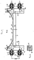
In den Zeichnungen zeigen:
- Figur 1:
- Eine Übersichtszeichnung über eine Siegelstation,
- Figur 2:
- einen Ausschnitt X aus der Siegelstation gemäß
Figur 1, - Figur 3:
- eine Übersichtsskizze einer Siegelstation mit einer Folienzuführung,
- Figur 4:
- eine Draufsicht auf eine Führung für einen Transportstab,
- Figur 5:
- eine Übersichtszeichnung für eine Öffnungsvorrichtung,
- Figur 6:
- einen Ausschnitt entlang der Schnittlinie VI - VI
in
Figur 4 und - Figur 7:
- eine Systemskizze zur Transportvorrichtung.
- Figure 1:
- An overview drawing of a sealing station,
- Figure 2:
- 1 shows a section X from the sealing station according to FIG. 1,
- Figure 3:
- an overview sketch of a sealing station with a film feed,
- Figure 4:
- a plan view of a guide for a transport rod,
- Figure 5:
- an overview drawing for an opening device,
- Figure 6:
- a section along the section line VI - VI in Figure 4 and
- Figure 7:
- a system sketch for the transport device.
Eine Vorrichtung zum Versiegeln von Verpackungsbehältern 1 besteht
im wesentlichen aus einer Siegelstation 2 und einer
Transportvorrichtung 3. Die Verpackungsbehälter 1 liegen mit
ihren Rändern 4 auf Transportstäben 5 auf, die zwischen einander
paralell verlaufenden Ketten sich quer zu deren Längsrichtung
erstrecken. Die Ketten 6 sind lediglich als strichpunktierte
Linien dargestellt. Sie werden von nicht dargestellten
Kettenrädern angetrieben und verlaufen durch die Siegelstation
2.A device for sealing
Diese Siegelstation 2 besteht im wesentlichen aus einem Oberwerkzeug
7 und einem Unterwerkzeug 8, die quer zur Längsrichtung
der Ketten 6 in Richtung auf einen zwischen den Transportstäben
5 hängenden Verpackungsbehälter 1 bewegt werden
können. Zur Durchführung dieser Bewegungsvorgänge sind jeweils
Antriebe vorhanden. Das Oberwerkzeug 7 wird von einem Pneumatikantrieb
10 quer zur Längsrichtung der Ketten 6 bewegt. Er
besteht aus einem Luftzylinder 9, in dem ein von Pressluft beaufschlagter
Kolben beweglich gelagert ist, an dessen Kolbenstange
11 das Oberwerkzeug 7 befestigt ist. Das Oberwerkzeug 7
ist mit einer elektrisch beheizten Siegelelektrode 18 ausgerüstet,
die an einer dem Verpackungsbehälter 1 zugewandten Unterseite
des Oberwerkzeuges 7 befestigt ist und über einen Anschluß
12 mit elektrischem Strom versorgt wird.This sealing station 2 essentially consists of an
Das Unterwerkzeug 8 wird von einem Hydraulikantrieb 13 quer
zur Längsrichtung der Ketten 6 in Richtung auf das Oberwerkzeug
7 bewegt. Dieser Hydraulikantrieb 13 besitzt einen
Hydraulikzylinder 14, in dem ein von einer Druckflüssigkeit
beaufschlagter nicht dargestellter Hydraulikkolben beweglich
gelagert ist. Dieser ist über einer Kolbenstange 15 mit dem
Unterwerkzeug 8 verbunden.The
An seiner dem Verpackungsbehälter 1 zugewandten Oberseite besitzt
das Unterwerkzeug 8 eine Ausnehmung 16, die der Form des
Verpackungsbehälters 1 angepaßt ist. Diese Ausnehmung 16 nimmt
den Verpackungsbehälter 1 auf, wenn das Unterwerkzeug 8 seine
dem Oberwerkzeug 7 zugewandte obere Position erreicht hat. Dabei
liegt der Verpackungsbehälter 1 mit seinem Rand 4 auf einer
die Ausnehmung 16 umgegebenden oberen Begrenzung 17 des
Unterwerkzeuges 8 auf und wird von dieser gegen die Versiegelungselektrode
18 des abgesenkten Oberwerkzeuges 7 gepreßt.
Dabei ist der Rand 4 von den ihn zuvor tragenden Transporstäben
5 abgehoben. Dabei wird der zu versiegelnde Verpackungsbehälter
1 lediglich um etwa 5 mm in Richtung auf die
Versiegelungselektrode 18 bewegt.Has on its top facing the
Die Versiegelung erfolgt in Höhe einer auf den Verpackungsbehälter
1 aufzusiegelnden Folie 19. Diese wird als eine Folienbahn
20 zwischen dem Oberwerkzeug 7 und dem Unterwerkzeug 8
hindurchgeführt. Sie verläuft oberhalb der Ketten 6 in einem
Abstand von etwa 5 mm. The sealing takes place at a level on the
Während der Durchführung der Versiegelung wird der Verpackungsbehälter
1 von der Transportvorrichtung 3 nicht weiter
befördert. Er ist von den Transportstäben 5 abgekoppelt.During the sealing process, the
Während des Aufsiegelns der Folie 19 der Siegelstation 2 ist
bereits ein nicht dargestellter Verschlußstreifen aus der Folienbahn
20 in der Größe einer Öffnung 21 aus der Folienbahn
20 ausgestanzt. Dieser ausgestanzte Verschlußstreifen wird mit
der Folienbahn 20 in Richtung auf die Siegelstation 2 transportiert
und dort auf die Ränder 4 des Verpackungsbehälters 1
aufgesiegelt. Nach der Beendigung dieser Versiegelung wird die
Folienbahn 20 in Richtung auf eine Aufwickelrolle 22 weiter
transportiert, indem sie zuvor an einer Umlenkrolle 23 aus der
Ebene umgelenkt worden ist, in der die Versiegelung stattgefunden
hat. Zwischen der Umlenkrolle 23 und der Aufwickelrolle
22 ist ein Bahnspannungshalter 24 mit einem federbelasteten
Hebel 25 vorgesehen. Auf die Aufwickelrolle 22 wird die Folienbahn
20 als ein Lochstreifen 26 aufgewickelt, dessen Löcher
durch das Ausstanzen der Verschlußstreifen entstanden sind.During the sealing of the film 19 of the sealing station 2
already a sealing strip, not shown, from the
Dieses Ausstanzen erfolgt zwischen zwei gegensinnig zueinander
rotierenden Walzen 27, 28, die in Förderrichtung vor der Siegelstation
2 angeordnet sind. Zwischen den beiden Walzen 27,
28 befindet sich ein Förderspalt 29 im Bereich der größten Annäherung
ihrer Walzenoberflächen 30, 31. Dieser Förderspalt 29
ist so ausgebildet, daß durch ihn die Folienbahn 20 hindurchgeleitet
werden kann, von den beiden gegenüberliegenden Walzenoberflächen
30, 31 jedoch so stark beaufschlagt wird, daß
die Folienbahn 20 entsprechend der Umdrehung der beiden Walzen
27, 28 durch einen Friktionsantrieb in Richtung auf die Siegelstation
2 gefördert wird. Dabei wird aus der Folienbahn 20
der Verschlußstreifen im Bereich des Förderspaltes 29 ausgestanzt.
Zu diesem Zwecke ist eine der beiden Walzen 28 mit einem
dem Verschlußstreifen entsprechenden Profil 32 auf ihrer
Oberfläche 31 versehen, während die Oberfläche 30 der anderen
Walze 27 glatt ist. Die mit der glatten Oberfläche 30 versehende
Walze 27 drückt die Folienbahn 20 auf das Profil 32, das
an seiner oberen Begrenzung mit Schneidkanten vergehen ist.
Dadurch wird aus der Folienbahn 20 der Verschlußstreifen ausgestanzt.
Er bleibt jedoch mit seinen Rändern im Bereich der
Folienbahn 20 und wird von dieser bis zur Siegelstation 2 gefördert.
Erst nachdem der Verschlußstreifen auf den Verpackungsbehälter
1 aufgesiegelt worden ist, ist innerhalb der Folienbahn
20 ein dem Verschlußstreifen entsprechendes Loch entstanden,
sodaß die Folienbahn 20 als Lochstreifen 26 in Richtung
auf die Aufwickelrolle 22 transportiert wird.This punching is done between two in opposite
Zur Abkoppelung des zu versiegelnden Verpackungsbehälters 1
von den Transportstäben 5 ist eine Öffnungsvorrichtung 33 vorgesehen,
mit deren Hilfe die Abkoppelung des Verpackungsbehälters
1 von den Transportstäben exakt in dem Zeitpunkt erfolgt,
in dem die Versiegelung des Verpackungsbehälters 1 stattfindet.
Zu diesem Zwecke sind 4 auf einer Grundplatte 34 jeweils
um Schwenkpunkten 35 schwenkbar gelagerte Hebel 36, 37 angeordnet,
von denen in der Figur 5 nur zwei einander gegenüberliegende
dargestellt sind. Diese Hebel 36, 37 überragen mit
ihren freien Enden 38, 39 die obere Begrenzung 17 des Unterwerkzeuges
8 und sind in diesem Bereich 38, 39 aus ihrem ansonsten
geraden Verlauf voneinander weg abgewinkelt. Darüberhinaus
werden die Hebel 36, 37 bei ihren Schwenkbewegungen um
die Schwenkpunkte 35 von Führungen 40, 41 gesteuert. Diese
Führungen 40, 41 können als reibungsarme nicht dargestellte
Steuerkurven ausgebildet sein. Sie sind so gestaltet, daß die
freien Enden 38, 39 beim Anheben des Unterwerkzeuges 8 hinter
eine jeweils dem Verpackungsbehälter 1 zugewandte Kante 42 der
den Rand 4 des Verpackungsbehälters 1 tragenden Transportstäbe
greifen. Beim weiteren Anheben der Grundplatte 34 und damit
des auf dieser gelagerten Unterwerkzeuges 8 führen die Hebel
36, 37 Schwenkbewegungen um den Schwenkpunkt 35 aus und verschieben
dabei die Transportstäbe 5 in einander entgegengesetzte
Richtungen 43, 44. Bei diesem Auseinanderschieben der
Transportstäbe 5 werden die Ränder 4 des Verpackungsbehälters
1 von diesen abgehoben, sodaß der Behälter 1 mit seinen Rändern
nunmehr auf der oberen Begrenzung 17 des Unterwerkzeuges
8 aufliegt und im übrigen von der Ausnehmung 16 aufgenommen
wird.To uncouple the packaging container to be sealed 1
an
Zu diesem Zwecke ist die Grundplatte 34 auf der Kolbenstange
15 des Hydraulikantriebes 13 befestigt. Auf diese Weise wird
eine ideale Synchronisation der Bewegungsvorgänge erzeugt, die
einerseits zum Verschwenken der Hebel 36, 37 und damit zum Abheben
des Verpackungsbehälters 1 von den Transportstäben 5
führt und andererseits zum Anheben des Unterwerkzeuges 8, mit
dessen Hilfe der Verpackungsbehälter 1 in Richtung auf das
Oberwerkzeug 7 angehoben und gegen die Versiegelungselektrode
18 gepreßt wird.For this purpose the
Auf Grund der vom Hydraulikantrieb 13 vorgenommenen Servosteuerung
des Unterwerkzeuges 8 wird dieses mit sehr geringer
Geschwindigkeit gegen die vergleichsweise teure Versiegelungselektrode
18 des Oberwerkzeuges 7 gefördert, sodaß sich der
mit dem Verschlußstreifen bedeckte Rand 4 des Verpackungsbehälters
1 sanft und ohne Stoß an die Versiegelungselektrode 18
anlegt. Dadurch werden mechanische Beschädigungen der Versiegelungselektrode
18 vermieden.Due to the servo control performed by the
Während des Siegeln wird der Verpackungsbehälter 1 nur ca. 5
mm angehoben, sodaß beim Versiegeln innerhalb des Verpackungsbehälters
1 das verpackte Produkt schonend behandelt wird.
Während des Siegelns ist der Kolben des Luftzylinders 9 etwa
1,5 mm in den Luftzylinder 9 hineingedrückt, bis er die zum
Versiegeln benötigte Gegenkraft gegenüber dem ihm beaufschlagenden
Unterwerkzeug 8 entfaltet. Der Hydraulikantrieb 13 wird
vom Drucköl gebremst, sodaß harte Anschläge durch mechanische
Endlagen vermieden werden.During the sealing, the
Die Verschiebung der Transportstäbe 5 erfolgt innerhalb von
Führungen 45, 46, die fest mit den im einzelnen dargestellten
Ketten 6 verbunden sind. Zu diesem Zwecke werden die einzelnen
Kettenglieder 47 über Schrauben 48 mit den Führungen 45, 46
verbunden. In den Führungen 45, 46 sind einander zugewandte
Führungsschlitze 49 vorgesehen, in die die Transportstäbe 5,
die einen rechteckigen Querschnitt aufweisen, mit ihren jeweiligen
Enden 50, 51 hineinragen und in denen sie zur Ausführung
von quer zu ihrer Längsrichtung verlaufenden Bewegungen geführt
werden.The displacement of the
Dabei liegen sie mit einer ihrer Längskanten 52, die in Verschieberichtung
53 der Transportstäbe 5 vorne liegt, an Blattfedern
54, 55 an, die an den Führungen 45, 46 befestigt sind.
Diese Befestigung erfolgt zweckmäßigerweise mit Hilfe von
Schrauben 56, 57, durch die die Blattfedern 54, 55 mit in Verschieberichtung
53 vorne liegenden Stirnflächen 58, 59 der
Führungen 45, 46 verschraubt sind.They lie with one of their
Die Stirnflächen 58, 59 verlaufen schräg zur Verschieberichtung
53 der Führungen 45, 46, etwa in einem Winkel von 45 °.
In entsprechender Weise verlaufen die Blattfedern 54, 55 in
ihren mit den Führungen 45, 46 verschraubten oberen Teilen 60,
61, die flach auf den Stirnflächen 58, 59 aufliegen. Gegenüber
dieser Richtung der Blattfedern 54, 55 sind sie im Bereich ihrer
den Transportstäben zugewandten unteren Enden 62, 63 in
eine paralell zu den Transportstäben 5 verlaufende Richtung
abgewinkelt, sodaß sie die Längskante 52 großflächig beaufschlagt.
Eine Verschiebung der Transportstäbe 5 kann daher nur
mit einer Verformung der Blattfedern 54, 55 in Verschieberichtung
53 einhergehen. Sobald die Beaufschlagung dieser Transportstäbe
5 in Verschieberichtung 53 beispielsweise durch die
Enden 38, 39 der Hebel 36, 37 endet, werden die Transportstäbe
5 von den Blattfedern 54, 55 wieder in ihre Ausgangslage zurückgeschoben.
In dieser liegen die Ränder 4 eines Verpackungsbehälters
1 auf einer quer zur Längskante 52 verlaufenden
oberen Fläche 64 eines jeden Transportstabes 5 auf.The end faces 58, 59 run obliquely to the direction of displacement
53 of the
Die gefüllten Verpackungsbehälter 1 werden mit ihren Rändern 4
auf den Transportstäben 5 abgesetzt. Diese fördern den Verpackungsbehälter
1, der in Transportrichtung 65 der Transportvorrichtung
3 von Seitenführungen 66, 67 geführt ist, in den Bereich
der Siegelstation 2. Paralell dazu werden die von den
beiden Walzen 27, 28 ausgeschnittenen Verschlußstreifen von
der Folienbahn 20 in den Bereich der Siegelstation 2 gefördert.The filled
In der Siegelstation 2 wird der zu versiegelnde Verpackungsbehälter
1 durch die Öffnungsvorrichtung 33 von den Transportstäben
5 getrennt, in dem der Hydraulikantrieb 13 die Grundplatte
34 und die auf ihnen schwenkbar gelagerten Hebel 36, 37
anhebt. Dabei greifen die Hebel 36, 37 mit ihren freien Enden
38, 39 hinter die Kante 42 der Transportstäbe 5 und werden
gleichzeitig durch die Führungen 40, 41 um die Schwenkpunkte
35 verschwenkt.In the sealing station 2 is the packaging container to be sealed
1 through the
Nach dem Abheben der Ränder 4 des Verpackungsbehälters 1 von
den Transportstäben 5 wird der Verpackungsbehälter 1 von der
Ausnehmung 16 des Unterwerkzeuges 8 aufgenommen und in Richung
auf daa Oberwerkzeug 7 gefördert. Dabei legt sich der Verschlußstreifen
auf die Ränder 4 des Verpackungsbehälters 1,
sodaß er aus der Folienbahn 20 herausgetrennt wird.After lifting the
Durch weiteres Anheben des Verpackungsbehälters 1 werden die
Ränder 4 und der die Öffnung des Verpackungsbehälters 1 verschließende
Verschlußstreifen gegen die heiße Versiegelungselektrode
18 des Oberwerkzeuges 7 gedrückt. Durch diesen aufgewendeten
Druck wird die Kolbenstange 11 des Pneumatikantriebes
10 um 1,5 mm in den Luftzylinder 9 hineingedrückt. In dieser
Stellung erzeugt der Pneumatikantrieb 10 den zum Versiegeln
des Verpackungsbehälters 1 notwendigen Gegendruck, sodaß
eine Versiegelung des Verschlußstreifens auf dem Verpackungsbehälter
1 stattfindet.By further lifting the
Sodann wird das Unterwerkzeug 8 wieder abgesenkt. Nachdem es
den Bereich der sich einander gegenüberliegenden Transportstäbe
5 verlassen hat, werden diese durch die Blattfedern 54,
55 wieder in ihre die Ränder 4 des Verpackungsbehälters 1 unterstützende
Ausgangslage zurückgedrückt, sodaß durch weiteren
Vorschub der Transportvorrichtung 3 der inzwischen versiegelten
Verpackungsbehälter 1 aus dem Bereich der Siegelstation 2
abgefördert wird. Durch das Absenken des Unterwerkzeuges 8
wird auch die Folienbahn 20 zum Weitertransport in Richtung
auf die Aufwickelrolle 22 entlastet, sodaß auf diese der nach
Entnahme des Verschlußstreifens verbliebene Lochstreifen aufgewickelt
werden kann.The
Claims (48)
Applications Claiming Priority (2)
| Application Number | Priority Date | Filing Date | Title |
|---|---|---|---|
| DE19740988A DE19740988A1 (en) | 1997-09-18 | 1997-09-18 | Device and method for sealing packaging containers |
| DE19740988 | 1997-09-18 |
Publications (1)
| Publication Number | Publication Date |
|---|---|
| EP0903291A2 true EP0903291A2 (en) | 1999-03-24 |
Family
ID=7842710
Family Applications (1)
| Application Number | Title | Priority Date | Filing Date |
|---|---|---|---|
| EP98117424A Withdrawn EP0903291A2 (en) | 1997-09-18 | 1998-09-15 | Apparatus and process for sealing packages |
Country Status (2)
| Country | Link |
|---|---|
| EP (1) | EP0903291A2 (en) |
| DE (1) | DE19740988A1 (en) |
Cited By (6)
| Publication number | Priority date | Publication date | Assignee | Title |
|---|---|---|---|---|
| FR2807391A1 (en) * | 2000-03-08 | 2001-10-12 | Bosch Gmbh Robert | SEALING DEVICE |
| EP1520809A1 (en) * | 2003-08-29 | 2005-04-06 | LIEDER MASCHINENBAU GmbH & Co. KG | Conveyor and method for adjusting to different sized containers |
| EP1700669A1 (en) * | 2005-03-12 | 2006-09-13 | UHLMANN PAC-SYSTEME GmbH & Co. KG | Lifting table |
| EP1714874A1 (en) * | 2005-04-19 | 2006-10-25 | Multivac Sepp Haggenmüller GmbH & Co. KG | Method of unwinding web material in a packaging machine and a packaging machine |
| WO2007088052A3 (en) * | 2006-02-01 | 2007-11-15 | Cfs Buehl Gmbh | Conveyor belts cooperating with the edge of a packaging tray |
| EP1990281A3 (en) * | 2007-05-11 | 2010-03-31 | Marcus Naroska | Method and device for sealing a rip-off film to a packaging element |
Families Citing this family (1)
| Publication number | Priority date | Publication date | Assignee | Title |
|---|---|---|---|---|
| DE102011105513A1 (en) | 2011-06-24 | 2012-12-27 | Multivac Sepp Haggenmüller Gmbh & Co. Kg | Method and sealing station for sealing packaging |
-
1997
- 1997-09-18 DE DE19740988A patent/DE19740988A1/en not_active Withdrawn
-
1998
- 1998-09-15 EP EP98117424A patent/EP0903291A2/en not_active Withdrawn
Cited By (8)
| Publication number | Priority date | Publication date | Assignee | Title |
|---|---|---|---|---|
| FR2807391A1 (en) * | 2000-03-08 | 2001-10-12 | Bosch Gmbh Robert | SEALING DEVICE |
| ES2190327A1 (en) * | 2000-03-08 | 2003-07-16 | Bosch Gmbh Robert | Plastics bag two-part heat sealing assembly with swivel-action lower section |
| ES2190327B1 (en) * | 2000-03-08 | 2004-08-01 | Robert Bosch Gmbh. | SEALING DEVICE. |
| EP1520809A1 (en) * | 2003-08-29 | 2005-04-06 | LIEDER MASCHINENBAU GmbH & Co. KG | Conveyor and method for adjusting to different sized containers |
| EP1700669A1 (en) * | 2005-03-12 | 2006-09-13 | UHLMANN PAC-SYSTEME GmbH & Co. KG | Lifting table |
| EP1714874A1 (en) * | 2005-04-19 | 2006-10-25 | Multivac Sepp Haggenmüller GmbH & Co. KG | Method of unwinding web material in a packaging machine and a packaging machine |
| WO2007088052A3 (en) * | 2006-02-01 | 2007-11-15 | Cfs Buehl Gmbh | Conveyor belts cooperating with the edge of a packaging tray |
| EP1990281A3 (en) * | 2007-05-11 | 2010-03-31 | Marcus Naroska | Method and device for sealing a rip-off film to a packaging element |
Also Published As
| Publication number | Publication date |
|---|---|
| DE19740988A1 (en) | 1999-03-25 |
Similar Documents
| Publication | Publication Date | Title |
|---|---|---|
| DE68903016T2 (en) | Device for closing containers by means of a sealable film. | |
| DE3707142C2 (en) | ||
| DE2943410C2 (en) | ||
| DE3610551A1 (en) | DEVICE FOR PRODUCING BENEFITS MADE FROM PLASTIC FILM LINES | |
| DE4307142C1 (en) | Grab on robot arm for flat flexible plastics items - has hollow spreader forming pressure accumulator for tools in mountings at sides | |
| EP0844063A2 (en) | Welding apparatus | |
| CH687016A5 (en) | Apparatus for separating stacked Ventilsaecken and for plugging the Ventilsaecke to or the filling of a Valve bag. | |
| EP1037803A1 (en) | Device for producing filled, sealed tubular pouch packaging | |
| DE19740988A1 (en) | Device and method for sealing packaging containers | |
| DE10157833B4 (en) | Apparatus for dividing a laminated glass sheet into individual laminated glass panes and method for positioning a laminated glass sheet on a laminated glass cutting plant | |
| DE3114190A1 (en) | Apparatus for the automatic filling and closing of carton containers | |
| EP0249946A2 (en) | Method and device for the fabrication of a spacing frame for insulating glass panes | |
| EP0462961A1 (en) | Apparatus for bending hollow spaces frames | |
| DE19747480C1 (en) | Machine cutting and fusing plastic plates | |
| EP1520809A1 (en) | Conveyor and method for adjusting to different sized containers | |
| CH634492A5 (en) | METHOD AND DEVICE FOR SEPARATING LENGTHED WIRE FORMING A LOOSE BUNDLE, IN PARTICULAR PURPOSE OF WIRE FEEDING TO A GRID WELDING MACHINE. | |
| DE2817597C2 (en) | Device for gluing the end of a running first material web to the beginning of a second material web | |
| EP0040170B1 (en) | Method and apparatus for fixing a tag to a plastic bag | |
| DE2351069C3 (en) | Machine for dividing foils, plates, trays or other objects in the transverse and longitudinal direction | |
| DE4441278A1 (en) | Cutting device for cutting tea=bags from paper web material | |
| EP1149020B1 (en) | Method and device for adapting the volume of a collar bag | |
| DE3880773T2 (en) | POUCH OPENING DEVICE. | |
| DE4208580A1 (en) | MANUALLY LOADED MACHINE FOR PROVIDING RIDERS ON SHEET MATERIAL | |
| DE19742107B4 (en) | Device for molding, punching and stacking containers made of a film of thermoplastic material | |
| DE2950553A1 (en) | Sack mfr. and filling machine - includes cutting station with tools to make seams and folds and includes filling socket and sack conveyor |
Legal Events
| Date | Code | Title | Description |
|---|---|---|---|
| PUAI | Public reference made under article 153(3) epc to a published international application that has entered the european phase |
Free format text: ORIGINAL CODE: 0009012 |
|
| AK | Designated contracting states |
Kind code of ref document: A2 Designated state(s): AT BE CH CY DE DK ES FI FR GB GR IE IT LI LU MC NL PT SE |
|
| AX | Request for extension of the european patent |
Free format text: AL;LT;LV;MK;RO;SI |
|
| STAA | Information on the status of an ep patent application or granted ep patent |
Free format text: STATUS: THE APPLICATION IS DEEMED TO BE WITHDRAWN |
|
| 18D | Application deemed to be withdrawn |
Effective date: 20010403 |