EP0903253B1 - Open roof construction for a vehicle - Google Patents
Open roof construction for a vehicle Download PDFInfo
- Publication number
- EP0903253B1 EP0903253B1 EP98202955A EP98202955A EP0903253B1 EP 0903253 B1 EP0903253 B1 EP 0903253B1 EP 98202955 A EP98202955 A EP 98202955A EP 98202955 A EP98202955 A EP 98202955A EP 0903253 B1 EP0903253 B1 EP 0903253B1
- Authority
- EP
- European Patent Office
- Prior art keywords
- roof
- open
- flow channel
- roof construction
- opening
- Prior art date
- Legal status (The legal status is an assumption and is not a legal conclusion. Google has not performed a legal analysis and makes no representation as to the accuracy of the status listed.)
- Expired - Lifetime
Links
- 238000010276 construction Methods 0.000 title claims description 25
- 230000007423 decrease Effects 0.000 claims description 5
- 230000000694 effects Effects 0.000 description 6
Images

Classifications
-
- B—PERFORMING OPERATIONS; TRANSPORTING
- B60—VEHICLES IN GENERAL
- B60J—WINDOWS, WINDSCREENS, NON-FIXED ROOFS, DOORS, OR SIMILAR DEVICES FOR VEHICLES; REMOVABLE EXTERNAL PROTECTIVE COVERINGS SPECIALLY ADAPTED FOR VEHICLES
- B60J7/00—Non-fixed roofs; Roofs with movable panels, e.g. rotary sunroofs
- B60J7/22—Wind deflectors for open roofs
Definitions
- the present invention relates to an open roof construction for a vehicle according to the preamble of claim 1.
- said arrangement is in the form of a wind deflector, which is fixedly mounted on the roof plate before the roof opening, or which is movably mounted on a frame within the roof opening.
- Such wind deflector functions to deflect the wind in upward direction away from the roof opening while driving.
- wind deflectors are no longer effective enough to prevent the occurrence of resonances between the air flow and the interior of the vehicle, the so-called "booming" effect.
- Various measures have been taken to modify the shape of the wind deflectors in order to lessen the above problem or eliminate it entirely, but these efforts have not been very successful.
- DE 1 008 592 B discloses an air guide channel in front of de roof opening on a vehicle.
- the channel has a width corresponding to the width of the roof, while the cross section of the channel decreases in the direction of its outlet.
- the air outlet is directed obliquely backwardly.
- Document DE 40 33 027 A is considered to be the closest prior art and discloses a device for reducing the noise and resonance in vehicle sliding roof openings experiencing tangential air flows. It comprises a disturbing body having a wedge shape in plan view. In one of the embodiments of Fig. 1, the body has two side walls converging in flow direction and being connected by a top wall at a distance from the vehicle roof skin.
- DE 43 34 011 C discloses an open roof construction for a vehicle having a device for influencing the air flow. It comprises a body which is pivotable around a pivot near its front side between a inactive position within the vehicle roof and an active position projecting from the roof.
- the object of the present invention is to provide an open roof construction wherein the above-described problem is eliminated, or alleviated, in an efficient manner.
- the open roof construction according to the invention is characterized by accelerating the air before the roof opening with a venturi of this type, it becomes possible to generate an air flow above the roof opening in a very effective way so that the "booming" problems no longer occur.
- the flow channel is formed under the roof plate, the appearance of the vehicle is hardly affected by this arrangement, if at all, and as the flow channel is bounded on the upper side by an adjustable part of the roof plate, the arrangement will only be activated when there is a need for it.
- the means for generating the air flow can be controlled automatically by means of a control unit, for example in dependence on the position of the closing element, the velocity of the vehicle and the like. In this way the most effective position of the means will be selected entirely automatically, which position can be influenced by various factors, but wherein the driver of the vehicle does not have to perform any operations himself.
- Fig. 1 is a perspective view of a part of a vehicle comprising the open roof construction according to the invention.
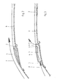
- Figs. 2 and 3 are longitudinal sectional views of a part of the vehicle of Fig. 1, wherein two different positions of the open roof construction are shown.
- Fig. 1 shows a vehicle comprising a roof plate 1, in which an opening 2 has been formed for the purpose of accommodating an open roof construction.
- the open roof construction comprises a closing element in the form of a rigid panel 3, which may or may not be transparent, and which closes the roof opening 2 in its closed position and which can be opened from said closed position, in any case by sliding the panel rearwardly under or over the roof plate 1.
- Closing element 3 may also be comprised of a foldable cover, slats or the like.
- the operating mechanism for the closing element 3, which is not shown, does not form part of the present invention.
- the roof opening 2 which is relatively large, can be exposed to a large extent by panel 3, and in practice said relatively large opening leads to the so-called "booming" problem, whereby resonances occur between the wind flowing over roof opening 2 and the interior of the vehicle.
- the invention provides means for generating an accelerated air flow over the roof opening, that is, an air flow having a velocity which is much larger than the velocity of the vehicle. In the illustrated embodiment this has been effected by fitting the roof plate 1 before the roof opening with one or more adjustable parts or flaps 4, under which a flow channel 5 has been formed.
- the arrows in Fig. 1 indicate the air flow through flow channel 5.
- Figs. 2 and 3 show the flap 4 in two different positions thereof. Flap 4 is closed in Fig. 2, because the panel 3 of the open roof construction is closed as well, so that the air flow F can flow over the closed flap 4 and the panel 3 without impediment.
- flap 4 is open, and in this position flap 4 has pivoted about a pin 6 present at the rear end of flap 4.
- an inlet 7 is formed on the front side of the flap, which inlet extends approximately horizontally and which scoops air into the flow channel 5, as it were.
- the air can leave the flow channel 5 again at an outlet 8, which sloped upwards to the rear at a relatively large angle.
- the width of the flow channel 5 of inlet 7 decreases towards outlet 8, whilst also the height of the flow channel 5 decreases from inlet 7 towards outlet 8, as is shown in Fig. 3.
- a venturi effect is created in flow channel 5, whereby the velocity of the inflowing air is increased considerably, so that air flows out at a high velocity at outlet 8. This high velocity prevents the "booming" effect in an effective manner.
- outlet 8 of flow channel 5 extends over only a small part of the width of roof opening 2, which may be sufficient to prevent the "booming" effect.
- Flow 5 may be given a greater width, or several flaps may be formed in side-by-side relationship in roof plate 1.
- the construction is selected so that the appearance of the vehicle is affected as little as possible, in any case in the inactive position of the arrangement.
- Flap 4 is preferably adjusted by means of an electric motor.
- the electric control makes it possible to adjust the flap depending on the position of closing element 3, for example, so that it is possible to generate an optimally advantageous air flow over roof opening 2 in any position of the panel.
- the invention provides an open roof construction and a vehicle fitted therewith, by means of which undesirable flow effects over the roof opening are prevented in an effective manner.
- the front part of the roof plate may form part of the vehicle, but it may also form part of the open roof construction.
- the open roof construction may be integrated in the entire roof plate.
Landscapes
- Engineering & Computer Science (AREA)
- Mechanical Engineering (AREA)
- Body Structure For Vehicles (AREA)
Description
- The present invention relates to an open roof construction for a vehicle according to the preamble of claim 1.
- With many known open roof constructions, said arrangement is in the form of a wind deflector, which is fixedly mounted on the roof plate before the roof opening, or which is movably mounted on a frame within the roof opening. Such wind deflector functions to deflect the wind in upward direction away from the roof opening while driving. In the course of the years, however, it has become apparent that, partially because roof openings are made larger and larger, wind deflectors are no longer effective enough to prevent the occurrence of resonances between the air flow and the interior of the vehicle, the so-called "booming" effect. Various measures have been taken to modify the shape of the wind deflectors in order to lessen the above problem or eliminate it entirely, but these efforts have not been very successful.
- DE 1 008 592 B, from which claim 1 has been delimited, discloses an air guide channel in front of de roof opening on a vehicle. The channel has a width corresponding to the width of the roof, while the cross section of the channel decreases in the direction of its outlet. In the embodiment of Fig. 3, the air outlet is directed obliquely backwardly.
- Document DE 40 33 027 A is considered to be the closest prior art and discloses a device for reducing the noise and resonance in vehicle sliding roof openings experiencing tangential air flows. It comprises a disturbing body having a wedge shape in plan view. In one of the embodiments of Fig. 1, the body has two side walls converging in flow direction and being connected by a top wall at a distance from the vehicle roof skin.
- DE 43 34 011 C discloses an open roof construction for a vehicle having a device for influencing the air flow. It comprises a body which is pivotable around a pivot near its front side between a inactive position within the vehicle roof and an active position projecting from the roof.
- The object of the present invention is to provide an open roof construction wherein the above-described problem is eliminated, or alleviated, in an efficient manner.
- In order to accomplish that object, the open roof construction according to the invention is characterized by accelerating the air before the roof opening with a venturi of this type, it becomes possible to generate an air flow above the roof opening in a very effective way so that the "booming" problems no longer occur.
- Since the flow channel is formed under the roof plate, the appearance of the vehicle is hardly affected by this arrangement, if at all, and as the flow channel is bounded on the upper side by an adjustable part of the roof plate, the arrangement will only be activated when there is a need for it.
- Great comfort is obtained if the means for generating the air flow can be controlled automatically by means of a control unit, for example in dependence on the position of the closing element, the velocity of the vehicle and the like. In this way the most effective position of the means will be selected entirely automatically, which position can be influenced by various factors, but wherein the driver of the vehicle does not have to perform any operations himself.
- The invention will be explained in more detail hereafter with reference to the drawings, which show an embodiment of the device according to the invention.
- Fig. 1 is a perspective view of a part of a vehicle comprising the open roof construction according to the invention.
- Figs. 2 and 3 are longitudinal sectional views of a part of the vehicle of Fig. 1, wherein two different positions of the open roof construction are shown.
- The drawing, and in the first instance Fig. 1, shows a vehicle comprising a roof plate 1, in which an
opening 2 has been formed for the purpose of accommodating an open roof construction. In this embodiment the open roof construction comprises a closing element in the form of arigid panel 3, which may or may not be transparent, and which closes the roof opening 2 in its closed position and which can be opened from said closed position, in any case by sliding the panel rearwardly under or over the roof plate 1. Closingelement 3 may also be comprised of a foldable cover, slats or the like. The operating mechanism for theclosing element 3, which is not shown, does not form part of the present invention. - The roof opening 2, which is relatively large, can be exposed to a large extent by
panel 3, and in practice said relatively large opening leads to the so-called "booming" problem, whereby resonances occur between the wind flowing overroof opening 2 and the interior of the vehicle. In order to prevent this effect, the invention provides means for generating an accelerated air flow over the roof opening, that is, an air flow having a velocity which is much larger than the velocity of the vehicle. In the illustrated embodiment this has been effected by fitting the roof plate 1 before the roof opening with one or more adjustable parts orflaps 4, under which aflow channel 5 has been formed. The arrows in Fig. 1 indicate the air flow throughflow channel 5. - Figs. 2 and 3 show the
flap 4 in two different positions thereof.Flap 4 is closed in Fig. 2, because thepanel 3 of the open roof construction is closed as well, so that the air flow F can flow over the closedflap 4 and thepanel 3 without impediment. - In Fig. 3
flap 4 is open, and in thisposition flap 4 has pivoted about apin 6 present at the rear end offlap 4. As a result of this, aninlet 7 is formed on the front side of the flap, which inlet extends approximately horizontally and which scoops air into theflow channel 5, as it were. The air can leave theflow channel 5 again at anoutlet 8, which sloped upwards to the rear at a relatively large angle. As is clearly shown in Fig. 1, the width of theflow channel 5 ofinlet 7 decreases towardsoutlet 8, whilst also the height of theflow channel 5 decreases frominlet 7 towardsoutlet 8, as is shown in Fig. 3. Thus, a venturi effect is created inflow channel 5, whereby the velocity of the inflowing air is increased considerably, so that air flows out at a high velocity atoutlet 8. This high velocity prevents the "booming" effect in an effective manner. - In the illustrated embodiment,
outlet 8 offlow channel 5 extends over only a small part of the width ofroof opening 2, which may be sufficient to prevent the "booming" effect.Flow 5 may be given a greater width, or several flaps may be formed in side-by-side relationship in roof plate 1. Instead of using an upwardly pivotingflap 4, it is also possible, of course, to open the inlet in a different manner, for example by sliding the flap in upward direction, by sliding away a closing element or the like. Preferably, the construction is selected so that the appearance of the vehicle is affected as little as possible, in any case in the inactive position of the arrangement.Flap 4 is preferably adjusted by means of an electric motor. Thus it is possible, for example, to build a small electric motor into the flap itself. The electric control makes it possible to adjust the flap depending on the position ofclosing element 3, for example, so that it is possible to generate an optimally advantageous air flow over roof opening 2 in any position of the panel. Furthermore it is possible to link the position ofvalve 4 to the velocity of the vehicle. - From the foregoing it will be apparent that the invention provides an open roof construction and a vehicle fitted therewith, by means of which undesirable flow effects over the roof opening are prevented in an effective manner.
- The invention is not limited to the above-described embodiment as shown in the drawing, which can be varied in several ways within the scope of the invention. Thus, the front part of the roof plate may form part of the vehicle, but it may also form part of the open roof construction. Alternatively, the open roof construction may be integrated in the entire roof plate.
Claims (9)
- An open roof construction for a vehicle having an opening (2) in the roof plate (1), said open roof construction comprising a closing element (3), which closes said roof opening in its closed position and which can be moved rearwards from said closed position to an open position, wherein means (4 - 8) is provided near the front edge of the roof opening for influencing the air flow above the roof opening when said closing element is at least partially open, said arrangement comprising a flow channel (5) formed as a venturi under the roof plate before the roof opening, and wherein said flow channel is provided with an inlet (7) and an outlet (8), the outlet sloping upwardly towards the rear,
characterized in that said flow channel (5), the outlet (8) of which extends only over part of the width of the roof opening, is bounded on the upper side by an adjustable part (4) of the roof plate (1) which is pivoted near its rear side. - An open roof construction according to claim 1, wherein the flow channel (5) is provided with an inlet (7) which extends approximately horizontally.
- An open roof construction according to claims 1 and 2, wherein the width of the flow channel (5) decreases in the direction of flow.
- An open roof construction according to one of the preceding claims, wherein the height of the flow channel (5) decreases in the direction of flow.
- An open roof construction according to claim 3, wherein the whole flow channel (5) only extend over part of the width of the roof opening (2).
- An open roof construction according to any one of the preceding claims, wherein the adjustable part (4) of the roof plate is a flap, which is vertically adjustable, at least on the front side, for selectively forming or closing the inlet (7) of the flow channel (5).
- An open roof construction according to any one of the preceding claims, wherein said means (4 - 8) for generating the air flow is electrically controlled.
- An open roof construction according to claim 7, wherein said means (4 - 8) for generating the air flow is automatically controlled by means of a control unit, for example in dependence on the position of the closing element (3), the velocity of the vehicle and the like.
- A vehicle having an opening in its roof plate, which is provided with the open roof construction according to any one of the preceding claims.
Applications Claiming Priority (2)
| Application Number | Priority Date | Filing Date | Title |
|---|---|---|---|
| NL1007065 | 1997-09-18 | ||
| NL1007065A NL1007065C2 (en) | 1997-09-18 | 1997-09-18 | Open roof construction for a vehicle. |
Publications (2)
| Publication Number | Publication Date |
|---|---|
| EP0903253A1 EP0903253A1 (en) | 1999-03-24 |
| EP0903253B1 true EP0903253B1 (en) | 2007-01-31 |
Family
ID=19765697
Family Applications (1)
| Application Number | Title | Priority Date | Filing Date |
|---|---|---|---|
| EP98202955A Expired - Lifetime EP0903253B1 (en) | 1997-09-18 | 1998-09-03 | Open roof construction for a vehicle |
Country Status (4)
| Country | Link |
|---|---|
| US (1) | US6086146A (en) |
| EP (1) | EP0903253B1 (en) |
| DE (1) | DE69836997T2 (en) |
| NL (1) | NL1007065C2 (en) |
Families Citing this family (23)
| Publication number | Priority date | Publication date | Assignee | Title |
|---|---|---|---|---|
| DE19802301A1 (en) * | 1998-01-22 | 1999-07-29 | Bosch Gmbh Robert | Wind deflector for a motor vehicle equipped with a sunroof |
| DE10013720C1 (en) * | 2000-03-21 | 2001-10-04 | Webasto Vehicle Sys Int Gmbh | Motor vehicle roof with transparent roof has pivoted ventilation flap integrated in front/rear strut next to glass panel |
| NL1015492C2 (en) * | 2000-06-21 | 2001-12-28 | Inalfa Ind Bv | Open roof construction for a vehicle. |
| DE10056754A1 (en) * | 2000-11-16 | 2002-05-23 | Daimler Chrysler Ag | Wind deflector for a sunroof opening of a motor vehicle |
| FR2820689B1 (en) * | 2001-02-12 | 2003-12-12 | Renault | SYSTEM FOR REDUCING THE OPENING ROOF BEAT IN A MOTOR VEHICLE |
| US6637805B2 (en) * | 2001-10-19 | 2003-10-28 | Clayton B. Rees | Apparatus and method for increasing downward force exerted on a spinning vehicle |
| US6742831B2 (en) * | 2001-10-19 | 2004-06-01 | Clayton B. Rees | Apparatus and method for increasing downward force exerted on a spinning vehicle |
| FR2842468B1 (en) * | 2002-07-22 | 2005-12-09 | France Design | AERODYNAMIC IMPROVEMENT FOR A DISCOVERABLE VEHICLE |
| DE20217642U1 (en) * | 2002-11-14 | 2004-05-27 | Inalfa Roof Systems Group B.V. | Wind deflector in open roof construction of vehicle has cover section in air inlet opening movable between retracted position in non-operating position of wind deflector and extended position in operating position of wind deflector |
| DE10323808B4 (en) * | 2003-05-23 | 2008-01-10 | Webasto Ag | Air guiding device for a vehicle roof |
| DE60306665T2 (en) * | 2003-12-18 | 2007-06-14 | Inalfa Roof Systems Group B.V. | Wind deflector and thus equipped openable roof construction |
| IT1390909B1 (en) * | 2008-07-16 | 2011-10-19 | Alenia Aeronautica Spa | STRUCTURAL ELEMENT WITH CALCULATED STIFFNESS, WITH TRANSFER ABSORPTION CHARACTERISTICS AND INTERSTIZI |
| US8353557B2 (en) | 2008-11-17 | 2013-01-15 | Inalfa Roof Systems Group B.V. | Movable wind deflector |
| US8240750B2 (en) * | 2009-12-01 | 2012-08-14 | Toyota Motor Engineering & Manufacturing North America, Inc. | Air duct system mating roof air ducts with headliner air ducts |
| US8303024B2 (en) * | 2010-02-22 | 2012-11-06 | Florida State University Research Foundation | Microjet control for flow and noise reduction in automotive applications |
| DE102010055578A1 (en) * | 2010-12-21 | 2012-06-21 | Volkswagen Ag | Convertible vehicle with at least one air flow guide |
| US8480161B2 (en) * | 2011-10-11 | 2013-07-09 | Raimund Pfaff | Drag reduction apparatus for a trailer |
| EP2596971B1 (en) | 2011-11-23 | 2016-01-27 | Inalfa Roof Systems Group B.V. | Open roof construction for a vehicle having an air guide |
| DE102013113142A1 (en) * | 2013-10-16 | 2015-04-16 | Dr. Ing. H.C. F. Porsche Aktiengesellschaft | Frame arrangement of a vehicle body |
| DE102013111412A1 (en) * | 2013-10-16 | 2015-04-30 | Dr. Ing. H.C. F. Porsche Aktiengesellschaft | Frame arrangement of a vehicle body |
| DE102014204284A1 (en) * | 2014-03-07 | 2015-09-10 | Volkswagen Aktiengesellschaft | Wind deflector for a vehicle and vehicle |
| US9399493B1 (en) * | 2015-03-23 | 2016-07-26 | Karl F. Milde, Jr. | Windshield air deflector for a motor vehicle |
| CN108698495B (en) * | 2016-02-18 | 2021-07-30 | 英纳法天窗系统集团有限公司 | Open roof structure for vehicles |
Family Cites Families (8)
| Publication number | Priority date | Publication date | Assignee | Title |
|---|---|---|---|---|
| DE1008592B (en) * | 1953-06-03 | 1957-05-16 | Daimler Benz Ag | Air duct in front of the roof opening on a motor vehicle, especially a passenger car |
| US2964352A (en) * | 1958-05-07 | 1960-12-13 | Werner Johannes | Device for influencing the current above the top of a motor vehicle |
| JPS5447743U (en) * | 1977-09-08 | 1979-04-03 | ||
| DE3833046A1 (en) * | 1988-09-29 | 1990-04-05 | Bayerische Motoren Werke Ag | Motor vehicle having a folding top and a wind deflector |
| DE4033027A1 (en) * | 1990-10-18 | 1992-04-23 | Bayerische Motoren Werke Ag | Sliding roof for private car - has wedges fitted to forward edge of roof opening to reduce low frequency noise |
| DE4334011C1 (en) * | 1993-10-06 | 1994-11-10 | Webasto Karosseriesysteme | Vehicle roof which can be opened, with a device for influencing the air flow |
| DE19549200A1 (en) * | 1995-12-30 | 1997-07-03 | Webasto Karosseriesysteme | Wind guide element for vehicle roof |
| US5671970A (en) * | 1996-02-21 | 1997-09-30 | Webasto Sunroofs, Inc. | Wind deflector for motor vehicle sunroof |
-
1997
- 1997-09-18 NL NL1007065A patent/NL1007065C2/en not_active IP Right Cessation
-
1998
- 1998-09-02 US US09/145,771 patent/US6086146A/en not_active Expired - Fee Related
- 1998-09-03 EP EP98202955A patent/EP0903253B1/en not_active Expired - Lifetime
- 1998-09-03 DE DE69836997T patent/DE69836997T2/en not_active Expired - Lifetime
Also Published As
| Publication number | Publication date |
|---|---|
| US6086146A (en) | 2000-07-11 |
| DE69836997T2 (en) | 2007-09-20 |
| EP0903253A1 (en) | 1999-03-24 |
| NL1007065C2 (en) | 1999-03-24 |
| DE69836997D1 (en) | 2007-03-22 |
Similar Documents
| Publication | Publication Date | Title |
|---|---|---|
| US6086146A (en) | Open roof construction for a vehicle | |
| US6942286B2 (en) | Retractable roof for vehicles | |
| US6523889B2 (en) | Device for influencing an air flow | |
| US4395939A (en) | Sunroof air screen | |
| US6357823B1 (en) | Device for influencing an air flow | |
| JP4156729B2 (en) | Open roof structure for vehicles | |
| JP4024871B2 (en) | A vehicle with a sliding canvas sunroof and a spoiler located in front of it | |
| US4396224A (en) | Wind deflector of a sunshine roof of vehicles | |
| EP1544015B1 (en) | Wind deflector and open roof construction provided therewith | |
| JP2000264071A (en) | Open roof structure for vehicle | |
| JPH04287715A (en) | Air screen device for open roof structure | |
| US1969935A (en) | Vehicle body ventilator and method | |
| US6499799B2 (en) | Open roof construction for a vehicle | |
| US6213543B1 (en) | Delector for automobile sunroof | |
| NL1013832C2 (en) | Open roof construction for a vehicle. | |
| JPH0569861A (en) | Car front structure | |
| KR100558740B1 (en) | Sunroof deflector hole switch | |
| KR100354120B1 (en) | Air vent for vehicle | |
| GB2292797A (en) | An adjustable air vent for a vehicle interior | |
| JPH039456Y2 (en) | ||
| KR0173617B1 (en) | Headrest rotating forward and backward | |
| JPH1178536A (en) | Deflector of sunroof | |
| JPH092077A (en) | Sunshine roof for automobile | |
| JP2022012410A (en) | Vehicle upper body structure | |
| CA2040778A1 (en) | Truck cab ventilator |
Legal Events
| Date | Code | Title | Description |
|---|---|---|---|
| PUAI | Public reference made under article 153(3) epc to a published international application that has entered the european phase |
Free format text: ORIGINAL CODE: 0009012 |
|
| AK | Designated contracting states |
Kind code of ref document: A1 Designated state(s): DE FR GB IT NL SE |
|
| AX | Request for extension of the european patent |
Free format text: AL;LT;LV;MK;RO;SI |
|
| 17P | Request for examination filed |
Effective date: 19990903 |
|
| AKX | Designation fees paid |
Free format text: DE FR GB IT NL SE |
|
| 17Q | First examination report despatched |
Effective date: 20010423 |
|
| RAP1 | Party data changed (applicant data changed or rights of an application transferred) |
Owner name: INALFA ROOF SYSTEMS GROUP B.V. |
|
| GRAP | Despatch of communication of intention to grant a patent |
Free format text: ORIGINAL CODE: EPIDOSNIGR1 |
|
| GRAS | Grant fee paid |
Free format text: ORIGINAL CODE: EPIDOSNIGR3 |
|
| GRAA | (expected) grant |
Free format text: ORIGINAL CODE: 0009210 |
|
| AK | Designated contracting states |
Kind code of ref document: B1 Designated state(s): DE FR GB IT NL SE |
|
| PG25 | Lapsed in a contracting state [announced via postgrant information from national office to epo] |
Ref country code: NL Free format text: LAPSE BECAUSE OF FAILURE TO SUBMIT A TRANSLATION OF THE DESCRIPTION OR TO PAY THE FEE WITHIN THE PRESCRIBED TIME-LIMIT Effective date: 20070131 |
|
| REG | Reference to a national code |
Ref country code: GB Ref legal event code: FG4D |
|
| REF | Corresponds to: |
Ref document number: 69836997 Country of ref document: DE Date of ref document: 20070322 Kind code of ref document: P |
|
| PG25 | Lapsed in a contracting state [announced via postgrant information from national office to epo] |
Ref country code: SE Free format text: LAPSE BECAUSE OF FAILURE TO SUBMIT A TRANSLATION OF THE DESCRIPTION OR TO PAY THE FEE WITHIN THE PRESCRIBED TIME-LIMIT Effective date: 20070430 |
|
| NLV1 | Nl: lapsed or annulled due to failure to fulfill the requirements of art. 29p and 29m of the patents act | ||
| EN | Fr: translation not filed | ||
| PLBE | No opposition filed within time limit |
Free format text: ORIGINAL CODE: 0009261 |
|
| STAA | Information on the status of an ep patent application or granted ep patent |
Free format text: STATUS: NO OPPOSITION FILED WITHIN TIME LIMIT |
|
| 26N | No opposition filed |
Effective date: 20071101 |
|
| PG25 | Lapsed in a contracting state [announced via postgrant information from national office to epo] |
Ref country code: IT Free format text: LAPSE BECAUSE OF FAILURE TO SUBMIT A TRANSLATION OF THE DESCRIPTION OR TO PAY THE FEE WITHIN THE PRESCRIBED TIME-LIMIT Effective date: 20070131 Ref country code: FR Free format text: LAPSE BECAUSE OF FAILURE TO SUBMIT A TRANSLATION OF THE DESCRIPTION OR TO PAY THE FEE WITHIN THE PRESCRIBED TIME-LIMIT Effective date: 20070921 |
|
| GBPC | Gb: european patent ceased through non-payment of renewal fee |
Effective date: 20070903 |
|
| PG25 | Lapsed in a contracting state [announced via postgrant information from national office to epo] |
Ref country code: GB Free format text: LAPSE BECAUSE OF NON-PAYMENT OF DUE FEES Effective date: 20070903 Ref country code: FR Free format text: LAPSE BECAUSE OF FAILURE TO SUBMIT A TRANSLATION OF THE DESCRIPTION OR TO PAY THE FEE WITHIN THE PRESCRIBED TIME-LIMIT Effective date: 20070131 |
|
| PGFP | Annual fee paid to national office [announced via postgrant information from national office to epo] |
Ref country code: DE Payment date: 20160922 Year of fee payment: 19 |
|
| REG | Reference to a national code |
Ref country code: DE Ref legal event code: R119 Ref document number: 69836997 Country of ref document: DE |
|
| PG25 | Lapsed in a contracting state [announced via postgrant information from national office to epo] |
Ref country code: DE Free format text: LAPSE BECAUSE OF NON-PAYMENT OF DUE FEES Effective date: 20180404 |