EP0902997B1 - Vorrichtung zum montieren wenigstens eines kabels in eine scheibe,welche zum positionieren in eine schutzmuffe einer kabelverbindung bestimmt ist - Google Patents
Vorrichtung zum montieren wenigstens eines kabels in eine scheibe,welche zum positionieren in eine schutzmuffe einer kabelverbindung bestimmt ist Download PDFInfo
- Publication number
- EP0902997B1 EP0902997B1 EP97926066A EP97926066A EP0902997B1 EP 0902997 B1 EP0902997 B1 EP 0902997B1 EP 97926066 A EP97926066 A EP 97926066A EP 97926066 A EP97926066 A EP 97926066A EP 0902997 B1 EP0902997 B1 EP 0902997B1
- Authority
- EP
- European Patent Office
- Prior art keywords
- disc
- cable
- passage
- securing
- cables
- Prior art date
- Legal status (The legal status is an assumption and is not a legal conclusion. Google has not performed a legal analysis and makes no representation as to the accuracy of the status listed.)
- Expired - Lifetime
Links
- 230000002093 peripheral effect Effects 0.000 claims description 4
- 238000005452 bending Methods 0.000 abstract description 6
- 238000007789 sealing Methods 0.000 description 14
- 230000001681 protective effect Effects 0.000 description 6
- 235000008612 Gnetum gnemon Nutrition 0.000 description 4
- 240000000018 Gnetum gnemon Species 0.000 description 4
- 238000009434 installation Methods 0.000 description 2
- 239000000463 material Substances 0.000 description 2
- 238000000465 moulding Methods 0.000 description 2
- 230000006978 adaptation Effects 0.000 description 1
- 230000015572 biosynthetic process Effects 0.000 description 1
- 230000000903 blocking effect Effects 0.000 description 1
- 239000011248 coating agent Substances 0.000 description 1
- 238000000576 coating method Methods 0.000 description 1
- 238000004891 communication Methods 0.000 description 1
- 230000007797 corrosion Effects 0.000 description 1
- 238000005260 corrosion Methods 0.000 description 1
- 230000003247 decreasing effect Effects 0.000 description 1
- 238000006073 displacement reaction Methods 0.000 description 1
- 230000000694 effects Effects 0.000 description 1
- 238000002347 injection Methods 0.000 description 1
- 239000007924 injection Substances 0.000 description 1
- 238000004519 manufacturing process Methods 0.000 description 1
- 210000002445 nipple Anatomy 0.000 description 1
- 238000007639 printing Methods 0.000 description 1
- 230000000717 retained effect Effects 0.000 description 1
- 230000035939 shock Effects 0.000 description 1
- 238000004804 winding Methods 0.000 description 1
Images


Classifications
-
- H—ELECTRICITY
- H02—GENERATION; CONVERSION OR DISTRIBUTION OF ELECTRIC POWER
- H02G—INSTALLATION OF ELECTRIC CABLES OR LINES, OR OF COMBINED OPTICAL AND ELECTRIC CABLES OR LINES
- H02G15/00—Cable fittings
- H02G15/013—Sealing means for cable inlets
-
- H—ELECTRICITY
- H02—GENERATION; CONVERSION OR DISTRIBUTION OF ELECTRIC POWER
- H02G—INSTALLATION OF ELECTRIC CABLES OR LINES, OR OF COMBINED OPTICAL AND ELECTRIC CABLES OR LINES
- H02G15/00—Cable fittings
- H02G15/007—Devices for relieving mechanical stress
-
- H—ELECTRICITY
- H02—GENERATION; CONVERSION OR DISTRIBUTION OF ELECTRIC POWER
- H02G—INSTALLATION OF ELECTRIC CABLES OR LINES, OR OF COMBINED OPTICAL AND ELECTRIC CABLES OR LINES
- H02G15/00—Cable fittings
- H02G15/08—Cable junctions
- H02G15/10—Cable junctions protected by boxes, e.g. by distribution, connection or junction boxes
- H02G15/117—Cable junctions protected by boxes, e.g. by distribution, connection or junction boxes for multiconductor cables
Definitions
- the present invention relates in a way general a protective sleeve used to isolate from environment the connected ends of cables, by example of communication network cables.
- Such sleeves are usually made in plastic and protect the connection mechanical shock and corrosion. They include manner known per se two disks arranged respectively around the incoming cable (s) and outgoing cable (s) and a generally cylindrical envelope positioned around said discs for sealing the space between these discs, in which the cable connection.
- the envelope is usually consisting of two shells fixed one on the other by their longitudinal edges, either of a split tube longitudinally.
- the present invention relates more particularly a device for mounting the one or more cables entering or leaving said sleeve in the discs.
- discs can be formed in one single piece with cable passage openings at through which cables, disks are threaded usually implemented are designed in several elements in order to allow their positioning and their fixation of on either side of the cable (s) without cutting said cables cables.
- Known devices most often have a disc in two elements for the passage of one or two cables, these being then positioned in the plane of joint of the two elements corresponding to a diameter of the disk. When three or four cables are to be maintained, the disc is separated into three elements, for example along two planes joint parallel to a diameter.
- the disc consists of two elements and is intended to be positioned in a protective sleeve of a cable connection.
- the disc further carries a cable mooring means, in the form of elements of clamping, which is held fixed relative to said disc by fixing means.
- This cable mooring means is separate from the means ensuring the tightness of the sleeve and is positioned behind the disc, inside the sleeve. Ways sealing, in the form of a wrapped strip, are arranged at the disk.
- the invention proposes to solve this problem by providing a device ensuring good quality mooring of cables entering and leaving the sleeve.
- a device for mounting at least one cable in a disc consisting of at least two elements is intended to be positioned in a protective sleeve for a cable connection, said disk carrying at least a cable mooring means kept fixed relative to said disc by means of fixing means.
- the device is characterized in that said mooring means is carried on the front face of said disc intended to be rotated towards the outside of the sleeve, and in that said mooring means comprises a mooring flange enclosed in a housing formed on the front face of the disc.
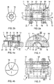
- a protective sleeve comprises in a manner known per se two discs 101, 102, respectively arranged around the or incoming cables and outgoing cable (s) and a generally cylindrical casing 100 positioned around said discs for sealing the space between these discs, only one half of said envelope 100 being shown.
- the discs are designed in two parts when are intended to hold one or two incoming cables or coming out of a protective sleeve, and in three elements when intended to hold more than two cables, for example four in Figures 5 to 10.
- the front face of a object is the outward facing side of the sleeve when this object is mounted in a sleeve.
- an element 1 of a disc produced in two elements generally have the shape of a half-cylinder and has a number of semi-cylindrical passages internal 10 equal to the number of cables that must be held in position in the disc.
- each semi-cylindrical passage 10 has two annular housings 18 arranged at a distance from each other.
- housings 18 are intended for positioning sealing washers 118, visible in FIG. 20, arranged on either side of a sealing means surrounding the cable, constituted for example by a ribbon wound on the cable or by a sealing gel.
- peripheral wall which borders said element is of such a diameter that it can be applied by means of a seal positioned in the groove 11 against the inner wall of the sleeve casing not shown in drawing.
- Said peripheral wall carries two ribs parallel 12 separated by a recess 13 so as to allow the longitudinal positioning of the disc in the envelope.
- said ribs 12 are arranged on either side of a rib formed on the inner face of the envelope so that it enters the recess 13. This arrangement allows avoid any longitudinal displacement of the discs in the envelope.
- the recess 13 is interrupted in a 13 'zone.
- the rib carried by the inner side of the envelope is also interrupted to allow the positioning of this zone 13 '.
- the rotation blocking of the disc in the envelope can be made even more efficient by the formation of fingers protruding from the internal face of the envelope and intended to be inserted into holes in the disk.
- two disc elements When mounting, two disc elements are positioned on either side of the cable or cables, bearing one on the other by their diametrical plane and are fixed one to the other by fixing means positioned in the openings 14.
- fixing means positioned in the openings 14.
- Lugs 15 visible in Figures 2b provide support screws to make them captive.
- keying means are positioned in the plane diametral of each element to ensure that the mounting of the disc is properly performed.
- the diametral plane of the disc member has a rib 16 on one side and a groove 17 on the other side.
- Said ribs 16 and grooves 17 are of similar section, for example that shown in enlargement in Figure 4b, and are positioned so that the rib 16 of the upper half enters the groove 17 of the half lower and vice versa for the rib 16 of the lower half and groove 17 of the upper half.
- These ribs and grooves are arranged transversely on the flat diametrical faces of disc elements so as to provide a connection between the sealing means arranged inside the disc, around the cables, and the sealing means arranged around the disc, against the envelope, which allows improve the tight fitting of the sleeve.
- This tightness can, in addition, be improved by coating the faces flat with sealing gel.
- the disc elements are made by molding plastic material.
- recesses are provided so as to reduce the volume of material and avoid realization of too thick walls. These recesses do not will not be described in detail here.
- the disc bears on its face forward directed outward from the sleeve a means for securing the cable (s) passing through it, said cable mooring means being kept fixed relative to the disc.
- FIG 20 shows schematically two variant embodiments of the invention.
- Disc 101 in which only one is placed cable, is in two elements each carrying a part of mooring flange 140. These mooring flange parts are attached to the disc by being molded in one piece with every element of the disc.
- the mooring means 141 is of the type of that which will be described later with reference to FIGS. 14 to 19, and is positioned in a housing 120 which the disk.
- each element 1 has a bowl 20 carried by its front face.
- This bowl 20 is generally parallelepipedic and has a semicircular opening 21 towards the front in the embodiments shown in the drawing, axially aligned with each semi-cylindrical passage 10 cable passage, it is formed by a wall 22 coming molding with the disc element 1.
- the open edge of the bowl 20 extends in the same plane as the plane diametral wall of element 1.
- the housing formed by the two bowls 20 when the disc elements are positioned one on top of the other is then closed housing.
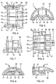
- Figures 8 to 13 show an example of production of a disc in three elements such as the disc 102 of FIG. 20, two edge elements shown in Figures 8 to 10 being intended to be positioned on either side and other of an intermediate element shown in the figures 11 to 13.
- two cables can be positioned between each of the edge elements 2 and the intermediate element 3. It could of course be provided to position only one cable between an element edge and the intermediate element so as to have two cables one above the other or three cables.
- the elements of such a three-part disc are designed by sharing said disc in two planes parallel to a diameter and arranged on either side of this one.
- the edge elements 2 are then elements having an outer wall consisting of a portion cylindrical smaller than that of a half-cylinder and a flat face. These edge elements have a height less than the radius of the disc.
- Intermediate element 3 has two faces planes connected by cylindrical portions.
- Said edge elements 2 include passages half-cylindrical 10 opening in their flat face and intended to cooperate with semi-cylindrical passages 10 opening in each flat face of the intermediate element 3.
- the semi-cylindrical passages 10 provided in one face of the intermediate element 3 are of different diameter from those on the other side, said diameters being very close to each other.
- edge elements are used to form the disc and keying means are provided on the flat faces in correspondence of said edge elements and the intermediate element.
- Fastening elements arranged in the openings 14 secure an edge element 2 to the intermediate element 3 by cooperating with means stop positioned in the recesses 35 of the openings 34 presented by the intermediate element in correspondence with each opening 14.
- the edge elements 2 have two openings 36 arranged respectively near their front face and near from their back side.
- the fixing means arranged in these openings 36 ensure the fixing of an edge element relative to the other by enclosing the intermediate element.
- the screw disposed in the opening 36 located at the rear crosses without opening the opening 37 of the element intermediate, while that positioned in the front opening 36 extends to the front of the housing created on the front face for the installation of the mooring means.
- the housing intended for positioning the mooring means is a double housing consisting of two bowls 20 formed respectively on each edge element 2 by a wall 22, and two bowls 23 formed on the element intermediate 3 by two walls in L 24 and a flat wall 25.
- the flat wall 25 is limited to a strip of weak size.
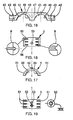
- the mooring means consist of a flange mooring and rings.
- Two embodiments of the mooring strap cables are available, one for mooring a cable, shown in Figures 14 and 15, and the other for securing two cables, shown in Figure 16.
- Cable mooring clamps consist of two halves 4 arranged. one on top of the other and other of the cable (s) to be moored.
- Each flange half has a central area 41 and two end zones 42 crossed by openings 43 intended for the passage of the fastening means retained by lugs 44.
- the central area 41 is overall overall parallelepiped and has one or two semi-cylindrical passages 45 for the passage of the cable or cables to be moored.
- the wall internal of the passages 45 carries protruding ribs 46.
- ribs 46 are provided along the length of the half flange.
- the flanges shown in the drawing have three ribs 46 regularly distributed on along the passage 45, these ribs 46 not extending over the entire circumference of passage 45 but only near the opening of the half flange.
- the upper face of the central area is flat and formed by stiffening ribs 47 arranged above tubular walls forming the semi-cylindrical passages 45.
- the two halves of the mooring strap are fixed one to the other after being arranged on either side of the or cables to be moored.
- Mooring rings are provided to fill the volume existing around the cable when it is not not of sufficient diameter to fill the semi-cylindrical passage 45.
- a set of several outer diameter rings and internally adapted so that they can be arranged one at a time in the others is proposed.
- the largest ring has an outer diameter equal to the diameter internal flanges, then each ring has an external diameter equal to the internal diameter of the previous ring in decreasing order of dimensions.
- the user positions around the cable he must connect the appropriate rings until the last ring is adapted to the internal passage 45 of the flange mooring.
- Positioning means are formed on said rings so as to facilitate their stacking and avoid their relative sliding with respect to other.
- These positioning means include grooves 51 carried by the outer surface of the rings, and ribs 56 carried by the internal surface of said rings.
- the grooves 51 of the largest ring are adapted to be positioned on the ribs 46 of the flange. These grooves are distributed over the surface of the ring in the same way as the ribs 46 of the flange and are of section adapted to be positioned on said ribs 46.
- the ribs 56 are ribs similar to the ribs 46 of the flange, distributed in the same manner as these.
- each ring The grooves 51 and ribs 56 of each ring are adapted to be positioned respectively on the larger ring ribs and in the smaller ring grooves.
- the positioning means further include a stud 52 adapted to be positioned in an opening 53.
- the stud 52 and the opening 53 are arranged in the upper area of the Ring.
- the flanges have an opening 48 similar to the openings 53 of rings so as to allow the positioning of the stud 52 of the largest ring.
- these are arranged head to tail in order to position the nipples in the openings.
- the user When making a connection, the user first places the rings, if they are necessary, around the cable taking care of start with an inner diameter ring a little less than the outer diameter of the cable. When stacking rings is finished, it positions the two halves of flange 4 and fixes them to each other. During this attachment, the smallest ring partially penetrates the cable sheath which ensures translation support said cable in said flange.
- the user then positions the washers sealing at distances from the flange specified by the supplier and then has a winding around the cable sealing tape when provided.
- the cable thus prepared is then positioned in a lower disc element chosen according to the number of cables to be connected.
- the sealing washers are positioned in the housings 18 while the flange mooring is arranged in the bowl 20.
- the lower element When the correct number of cables has been arranged in the lower element, it is capped by an upper half or by an intermediate element of disc taking care to re-position the sealing washers in housings 18 and the bowl 20 or the bowl 23 around the sealing flange. The two disc elements are then fixed to each other.
- the wall 25 separating the two bowls 23 from a intermediate element is of sufficient size to be applied against the upper face of the flange mooring.
- this gel is injected by a injection hole after fixing the elements of disk.
- each mooring strap is enclosed in a housing formed on the face. front of the disc, i.e. on the side intended to be turned towards the outside of the sleeve when the envelope is put in place.
- the dimensions of the mooring flanges and disc slots in which they are positioned are such that said flanges are kept fixed at against any movement.
- the cables are therefore kept at the level of their entering the disc in a fixed position by report to disk regardless of the efforts of traction, torsion or bending, which are applied to them the outside of the sleeve.
- the invention can be implemented in different sleeves of known types, an opening 6 such than that shown by way of example in FIGS. 1 and 4a can be used for the installation of a valve pressurization or a grounding terminal.
Landscapes
- Installation Of Indoor Wiring (AREA)
- Insertion, Bundling And Securing Of Wires For Electric Apparatuses (AREA)
- Multi-Conductor Connections (AREA)
- Cable Accessories (AREA)
Claims (12)
- Vorrichtung zur Montage mindestens eines Kabels in einer aus mindestens zwei Elementen bestehenden Scheibe, zur Anordnung einer Kabelverbindung in einer Schutzmuffe, wobei die Scheibe (102; 1, 1; 2, 3, 2) mindestens ein ihr gegenüber durch Befestigungsmittel fixiertes Seilverankerungsmittel (141; 4, 4) trägt, dadurch gekennzeichnet, daß das Verankerungsmittel an der der Außenseite der Muffe zugewandten Vorderseite der Scheibe angeordnet ist und einen in einem an der Vorderseite der Scheibe (102; 1, 1; 2, 3, 2) ausgebildeten Ausnehmung (120; 20, 20; 20, 23, 20) aufgenommenen Verankerungsflansch (141; 4, 4) umfaßt.
- Vorrichtung nach Anspruch 1, dadurch gekennzeichnet, daß bei einer aus zwei Elementen (1) bestehenden Scheibe (1, 1) jedes Element (1) eine an seiner Vorderseite angeordnete Wanne (20) aufweist.
- Vorrichtung nach Anspruch 2, dadurch gekennzeichnet, daß bei einer aus drei Elementen bestehenden Scheibe (2, 3, 2) die für die Anordnung des Verankerungsmittels vorgesehene Ausnehmung jeweils an jedem Randelement (2) aus zwei Wannen (20) und aus zwei am Zwischenelement ausgebildeten Wannen (23) besteht.
- Vorrichtung nach Anspruch 2 oder 3, dadurch gekennzeichnet, daß die Wanne (20) insgesamt parallelepipedisch ist und vorne mindestens eine Öffnung (21) aufweist, wobei jede Öffnung (21) axial zu jeder Kabeldurchführung (10) durch die Scheibe (1, 1) ausgerichtet ist.
- Vorrichtung nach einem der Ansprüche 1 bis 4, dadurch gekennzeichnet, daß die Ausnehmung (20, 20; 20, 23, 20) durch Wände (22, 24, 25) begrenzt wird, die durch Gießen mit den Scheibenelementen entstanden sind.
- Vorrichtung nach einem der vorhergehenden Ansprüche, dadurch gekennzeichnet, daß die Scheiben durch das Zusammenwirken von zwei parallelen und durch einen Einsprung (13) der Umfangswand der Scheibe getrennten Rippen (12) mit einer an der Innenseite der Muffe gebildeten Rippe in einem Mantel angeordnet sind, wobei der Einsprung (13) in einem in einer Unterbrechung der an der Innenseite der Muffe angeordneten Rippe befindlichen Bereich (13') unterbrochen ist.
- Vorrichtung nach einem der Ansprüche 1 bis 6, dadurch gekennzeichnet, daß der Kabelverankerungsflansch aus zwei aneinander und beidseits des zu verankernden Kabels zu befestigenden Hälften (4) besteht, wobei jede Flanschhälfte (4) einen insgesamt einen parallelepipedischen Raum einnehmenden Mittelteil (41) aufweist und mindestens einen halbzylindrischen Durchbruch (45) für die Durchführung des oder der zu verankernden Kabel und zwei Endbereiche (42) mit Öffnungen (43) für den Durchtritt der Befestigungsmittel umfaßt.
- Vorrichtung nach Anspruch 7, dadurch gekennzeichnet, daß die Innenwand des Durchbruchs(45) mindestens eine überstehende Rippe (46) aufweist.
- Vorrichtung nach einem der vorhergehenden Ansprüche, dadurch gekennzeichnet, daß das Verankerungsmittel der stapelbaren Verankerungsringe (5,5) für die Anordnung im Verankerungsflansch bestimmt ist.
- Vorrichtung nach Anspruch 9, dadurch gekennzeichnet, daß die Verankerungsringe Positioniermittel haben, um ihre Stapelung zu erleichtern und ihr gegenseitiges Verrutschen zu vermeiden.
- Vorrichtung nach Anspruch 10, dadurch gekennzeichnet, daß die Positioniermittel auf der Außenfläche der Ringe angeordnete Nuten (51) und auf der Innenfläche dieser Ringe angeordnete Rippen (56) aufweisen.
- Vorrichtung nach Anspruch 10, dadurch gekennzeichnet, daß die Positioniermittel einen zur Anordnung in einer Öffnung (53) vorgesehenen Vorsprung (52) umfassen, wobei der Vorsprung (52) und die Öffnung (53) im oberen Bereich des Rings angeordnet sind.
Applications Claiming Priority (3)
| Application Number | Priority Date | Filing Date | Title |
|---|---|---|---|
| FR9606911A FR2749712B1 (fr) | 1996-06-05 | 1996-06-05 | Dispositif pour le montage d'au moins un cable dans un disque destine a etre positionne dans un manchon de protection d'un raccordement de cables |
| FR9606911 | 1996-06-05 | ||
| PCT/FR1997/000950 WO1997047063A1 (fr) | 1996-06-05 | 1997-06-02 | Dispositif pour le montage d'au moins un cable dans un disque destine a etre positionne dans un manchon de protection d'un raccordement de cables |
Publications (2)
| Publication Number | Publication Date |
|---|---|
| EP0902997A1 EP0902997A1 (de) | 1999-03-24 |
| EP0902997B1 true EP0902997B1 (de) | 2001-09-12 |
Family
ID=9492728
Family Applications (1)
| Application Number | Title | Priority Date | Filing Date |
|---|---|---|---|
| EP97926066A Expired - Lifetime EP0902997B1 (de) | 1996-06-05 | 1997-06-02 | Vorrichtung zum montieren wenigstens eines kabels in eine scheibe,welche zum positionieren in eine schutzmuffe einer kabelverbindung bestimmt ist |
Country Status (9)
| Country | Link |
|---|---|
| US (1) | US6198048B1 (de) |
| EP (1) | EP0902997B1 (de) |
| AT (1) | ATE205643T1 (de) |
| BR (1) | BR9709518A (de) |
| DE (1) | DE69706677T2 (de) |
| ES (1) | ES2160354T3 (de) |
| FR (1) | FR2749712B1 (de) |
| PT (1) | PT902997E (de) |
| WO (1) | WO1997047063A1 (de) |
Families Citing this family (7)
| Publication number | Priority date | Publication date | Assignee | Title |
|---|---|---|---|---|
| EP1078429B1 (de) | 1998-04-24 | 2004-12-29 | Cekan/CDT A/S | Zugentlastete eingeführte verbindung für signalkabel mit verdrillten drahtpaaren |
| WO2001013485A1 (de) * | 1999-08-13 | 2001-02-22 | Rxs Gesellschaft Für Vermögensverwaltung Mbh | Universale kabelgarnitur |
| US6380490B1 (en) * | 2000-06-16 | 2002-04-30 | Charles O. Gaston | Electric fence insulator |
| DE102006036233B4 (de) * | 2006-08-03 | 2008-03-27 | Nkt Cables Gmbh | Freiluftendverschluss |
| JP5798777B2 (ja) * | 2011-04-04 | 2015-10-21 | 矢崎総業株式会社 | ワッシャ保持用ブラケット構造 |
| DE102015115222A1 (de) * | 2015-09-10 | 2017-03-16 | Kiekert Ag | Schiebetürantrieb eines Kraftfahrzeugs |
| CN118040599B (zh) * | 2024-04-09 | 2024-06-21 | 洛阳祥和电缆有限公司 | 一种电缆接头塑封装置 |
Family Cites Families (9)
| Publication number | Priority date | Publication date | Assignee | Title |
|---|---|---|---|---|
| GB191228094A (en) * | 1912-12-05 | 1913-04-24 | Henleys Telegraph Works Co Ltd | Improvements in Joint Boxes for Electrical Cables. |
| DE7425454U (de) * | 1974-07-25 | 1974-11-07 | Siemens Ag | Lippenförmiger Dichtungskörper für Kabelmuffen |
| DE2731578C3 (de) * | 1977-07-13 | 1981-04-16 | Müller, Siegfried, 5800 Hagen | Kabelmuffe mit metallischem Stützmantel und beidseitig an diesen anschließenden Muffenköpfen sowie ein diese Teile miteinander verbindenden Kunststoffschrumfschlauch |
| US4704499A (en) * | 1986-06-18 | 1987-11-03 | American Telephone And Telegraph Company At&T Bell Laboratories | Locking mechanism for aerial cable closure and terminals |
| CA1318948C (en) * | 1987-11-18 | 1993-06-08 | Takayuki Nimiya | Cable closure |
| US5313019A (en) * | 1988-11-09 | 1994-05-17 | N.V. Raychem S.A. | Closure assembly |
| DE4142586C2 (de) * | 1991-12-21 | 1994-07-28 | Rose Walter Gmbh & Co Kg | Verbindungs- und Abzweigmuffe für Fernmeldekabel, Koaxialkabel oder Glasfaserkabel |
| GB9324665D0 (en) * | 1993-12-01 | 1994-01-19 | Raychem Sa Nv | Environmental seal |
| DE4429658C1 (de) * | 1994-08-20 | 1996-02-01 | Nbb Nachrichtentech Gmbh | Anschlusselement für ein Kabel |
-
1996
- 1996-06-05 FR FR9606911A patent/FR2749712B1/fr not_active Expired - Fee Related
-
1997
- 1997-06-02 ES ES97926066T patent/ES2160354T3/es not_active Expired - Lifetime
- 1997-06-02 EP EP97926066A patent/EP0902997B1/de not_active Expired - Lifetime
- 1997-06-02 DE DE69706677T patent/DE69706677T2/de not_active Expired - Fee Related
- 1997-06-02 WO PCT/FR1997/000950 patent/WO1997047063A1/fr not_active Ceased
- 1997-06-02 AT AT97926066T patent/ATE205643T1/de not_active IP Right Cessation
- 1997-06-02 US US09/194,852 patent/US6198048B1/en not_active Expired - Fee Related
- 1997-06-02 PT PT97926066T patent/PT902997E/pt unknown
- 1997-06-02 BR BR9709518A patent/BR9709518A/pt not_active IP Right Cessation
Also Published As
| Publication number | Publication date |
|---|---|
| ATE205643T1 (de) | 2001-09-15 |
| DE69706677D1 (de) | 2001-10-18 |
| ES2160354T3 (es) | 2001-11-01 |
| US6198048B1 (en) | 2001-03-06 |
| WO1997047063A1 (fr) | 1997-12-11 |
| FR2749712B1 (fr) | 1998-08-14 |
| PT902997E (pt) | 2001-12-28 |
| EP0902997A1 (de) | 1999-03-24 |
| FR2749712A1 (fr) | 1997-12-12 |
| DE69706677T2 (de) | 2002-06-20 |
| BR9709518A (pt) | 1999-08-10 |
Similar Documents
| Publication | Publication Date | Title |
|---|---|---|
| EP0808008B1 (de) | Abgedichtetes Kabelverbindungsgehäuse | |
| EP1110023B1 (de) | Abgedichtete kupplung mit verstellbarer geometrie | |
| FR2728079A1 (fr) | Dispositif de maintien d'au moins un cable a fibres optiques et boitier d'epissurage en faisant application | |
| FR2473151A1 (fr) | Dispositif de raccordement de tuyaux | |
| EP0942507B1 (de) | Abgedichtetes Gehäuse einer Vorrichtung mit Zugang zu einem Kabel | |
| EP0902997B1 (de) | Vorrichtung zum montieren wenigstens eines kabels in eine scheibe,welche zum positionieren in eine schutzmuffe einer kabelverbindung bestimmt ist | |
| FR2885745A1 (fr) | Boite d'encastrement et procede de fabrication | |
| FR2573842A1 (fr) | Appareil pour connecter des tubes aboutes alignes et pour maintenir leur alignement rotatif pendant la connexion | |
| EP2366189A1 (de) | Busbar-muffe mit einem dem verbinder gewidmeten orientierungsmässig justierbaren schutzgehäuse | |
| EP3106587A1 (de) | Befestigungsvorrichtung eines in einem unterwasserbecken versenkten objekts | |
| FR3126807A1 (fr) | Fiche audio | |
| EP0490725B1 (de) | Abdichtungsvorrichtung einer rohrförmigen Kabeldurchführung | |
| FR2589210A1 (fr) | Dispositif de fixation d'un culot de maintien sur l'extremite d'un cable | |
| FR2735175A1 (fr) | Gond de reception d'une penture de volet, du type a axe rapporte | |
| EP1378975B1 (de) | In einem Sachlloch einsetzbare elektrische Verbindungseinrichtung | |
| BE1012055A3 (fr) | Dispositif de fixation par ecrou. | |
| FR2737763A1 (fr) | Piece formant joint et dispositif comprenant la piece formant joint | |
| EP0599673A1 (de) | Verbinderhülse für abgedichtete Durchführung und dazugehörige Anordnung | |
| FR2686195A1 (fr) | Dispositif pour raccorder de facon demontable des cables electriques en moyenne tension. | |
| FR2749713A1 (fr) | Manchon de protection d'un raccordement de cables | |
| FR2702928A3 (fr) | Réceptacle pour le logement de cordons, notamment de fils de lignes pour cannes à pêche. | |
| FR2724969A3 (fr) | Anti-vol a cable d'acier | |
| FR2673697A1 (fr) | Dispositif d'orientation de cable. | |
| FR2804463A1 (fr) | Dispositif formant support d'extremite pour un arbre d'enroulement et mecanisme de manoeuvre d'une installation de fermeture ou de protection solaire equipe d'un tel dispositif | |
| FR2573583A1 (fr) | Dispositif pour le guidage d'objets allonges tels que des cables a travers une paroi |
Legal Events
| Date | Code | Title | Description |
|---|---|---|---|
| PUAI | Public reference made under article 153(3) epc to a published international application that has entered the european phase |
Free format text: ORIGINAL CODE: 0009012 |
|
| 17P | Request for examination filed |
Effective date: 19980928 |
|
| AK | Designated contracting states |
Kind code of ref document: A1 Designated state(s): AT BE CH DE DK ES FI FR GB GR IE IT LI LU NL PT SE |
|
| 17Q | First examination report despatched |
Effective date: 20000913 |
|
| GRAG | Despatch of communication of intention to grant |
Free format text: ORIGINAL CODE: EPIDOS AGRA |
|
| GRAG | Despatch of communication of intention to grant |
Free format text: ORIGINAL CODE: EPIDOS AGRA |
|
| GRAH | Despatch of communication of intention to grant a patent |
Free format text: ORIGINAL CODE: EPIDOS IGRA |
|
| GRAH | Despatch of communication of intention to grant a patent |
Free format text: ORIGINAL CODE: EPIDOS IGRA |
|
| GRAA | (expected) grant |
Free format text: ORIGINAL CODE: 0009210 |
|
| ITF | It: translation for a ep patent filed | ||
| AK | Designated contracting states |
Kind code of ref document: B1 Designated state(s): AT BE CH DE DK ES FI FR GB GR IE IT LI LU NL PT SE |
|
| PG25 | Lapsed in a contracting state [announced via postgrant information from national office to epo] |
Ref country code: NL Free format text: LAPSE BECAUSE OF FAILURE TO SUBMIT A TRANSLATION OF THE DESCRIPTION OR TO PAY THE FEE WITHIN THE PRESCRIBED TIME-LIMIT Effective date: 20010912 Ref country code: IE Free format text: LAPSE BECAUSE OF FAILURE TO SUBMIT A TRANSLATION OF THE DESCRIPTION OR TO PAY THE FEE WITHIN THE PRESCRIBED TIME-LIMIT Effective date: 20010912 Ref country code: GB Free format text: LAPSE BECAUSE OF FAILURE TO SUBMIT A TRANSLATION OF THE DESCRIPTION OR TO PAY THE FEE WITHIN THE PRESCRIBED TIME-LIMIT Effective date: 20010912 Ref country code: FI Free format text: LAPSE BECAUSE OF FAILURE TO SUBMIT A TRANSLATION OF THE DESCRIPTION OR TO PAY THE FEE WITHIN THE PRESCRIBED TIME-LIMIT Effective date: 20010912 Ref country code: AT Free format text: LAPSE BECAUSE OF FAILURE TO SUBMIT A TRANSLATION OF THE DESCRIPTION OR TO PAY THE FEE WITHIN THE PRESCRIBED TIME-LIMIT Effective date: 20010912 |
|
| REF | Corresponds to: |
Ref document number: 205643 Country of ref document: AT Date of ref document: 20010915 Kind code of ref document: T |
|
| REG | Reference to a national code |
Ref country code: CH Ref legal event code: EP |
|
| REG | Reference to a national code |
Ref country code: IE Ref legal event code: FG4D Free format text: FRENCH |
|
| REF | Corresponds to: |
Ref document number: 69706677 Country of ref document: DE Date of ref document: 20011018 |
|
| REG | Reference to a national code |
Ref country code: ES Ref legal event code: FG2A Ref document number: 2160354 Country of ref document: ES Kind code of ref document: T3 |
|
| PG25 | Lapsed in a contracting state [announced via postgrant information from national office to epo] |
Ref country code: SE Free format text: LAPSE BECAUSE OF FAILURE TO SUBMIT A TRANSLATION OF THE DESCRIPTION OR TO PAY THE FEE WITHIN THE PRESCRIBED TIME-LIMIT Effective date: 20011212 Ref country code: DK Free format text: LAPSE BECAUSE OF FAILURE TO SUBMIT A TRANSLATION OF THE DESCRIPTION OR TO PAY THE FEE WITHIN THE PRESCRIBED TIME-LIMIT Effective date: 20011212 |
|
| PG25 | Lapsed in a contracting state [announced via postgrant information from national office to epo] |
Ref country code: GR Free format text: LAPSE BECAUSE OF FAILURE TO SUBMIT A TRANSLATION OF THE DESCRIPTION OR TO PAY THE FEE WITHIN THE PRESCRIBED TIME-LIMIT Effective date: 20011214 |
|
| REG | Reference to a national code |
Ref country code: PT Ref legal event code: SC4A Free format text: AVAILABILITY OF NATIONAL TRANSLATION Effective date: 20010912 |
|
| NLV1 | Nl: lapsed or annulled due to failure to fulfill the requirements of art. 29p and 29m of the patents act | ||
| GBV | Gb: ep patent (uk) treated as always having been void in accordance with gb section 77(7)/1977 [no translation filed] |
Effective date: 20010912 |
|
| PGFP | Annual fee paid to national office [announced via postgrant information from national office to epo] |
Ref country code: CH Payment date: 20020521 Year of fee payment: 6 |
|
| REG | Reference to a national code |
Ref country code: IE Ref legal event code: FD4D |
|
| PG25 | Lapsed in a contracting state [announced via postgrant information from national office to epo] |
Ref country code: LU Free format text: LAPSE BECAUSE OF NON-PAYMENT OF DUE FEES Effective date: 20020602 |
|
| PG25 | Lapsed in a contracting state [announced via postgrant information from national office to epo] |
Ref country code: BE Free format text: LAPSE BECAUSE OF NON-PAYMENT OF DUE FEES Effective date: 20020630 |
|
| PLBE | No opposition filed within time limit |
Free format text: ORIGINAL CODE: 0009261 |
|
| STAA | Information on the status of an ep patent application or granted ep patent |
Free format text: STATUS: NO OPPOSITION FILED WITHIN TIME LIMIT |
|
| 26N | No opposition filed | ||
| BERE | Be: lapsed |
Owner name: S.A. *POUYET Effective date: 20020630 |
|
| PG25 | Lapsed in a contracting state [announced via postgrant information from national office to epo] |
Ref country code: LI Free format text: LAPSE BECAUSE OF NON-PAYMENT OF DUE FEES Effective date: 20030630 Ref country code: CH Free format text: LAPSE BECAUSE OF NON-PAYMENT OF DUE FEES Effective date: 20030630 |
|
| REG | Reference to a national code |
Ref country code: CH Ref legal event code: PL |
|
| PGFP | Annual fee paid to national office [announced via postgrant information from national office to epo] |
Ref country code: PT Payment date: 20040527 Year of fee payment: 8 |
|
| PGFP | Annual fee paid to national office [announced via postgrant information from national office to epo] |
Ref country code: FR Payment date: 20040618 Year of fee payment: 8 |
|
| PGFP | Annual fee paid to national office [announced via postgrant information from national office to epo] |
Ref country code: ES Payment date: 20040708 Year of fee payment: 8 |
|
| PGFP | Annual fee paid to national office [announced via postgrant information from national office to epo] |
Ref country code: DE Payment date: 20040802 Year of fee payment: 8 |
|
| PG25 | Lapsed in a contracting state [announced via postgrant information from national office to epo] |
Ref country code: IT Free format text: LAPSE BECAUSE OF NON-PAYMENT OF DUE FEES Effective date: 20050602 |
|
| PG25 | Lapsed in a contracting state [announced via postgrant information from national office to epo] |
Ref country code: ES Free format text: LAPSE BECAUSE OF NON-PAYMENT OF DUE FEES Effective date: 20050603 |
|
| PG25 | Lapsed in a contracting state [announced via postgrant information from national office to epo] |
Ref country code: PT Free format text: LAPSE BECAUSE OF NON-PAYMENT OF DUE FEES Effective date: 20051202 |
|
| PG25 | Lapsed in a contracting state [announced via postgrant information from national office to epo] |
Ref country code: DE Free format text: LAPSE BECAUSE OF NON-PAYMENT OF DUE FEES Effective date: 20060103 |
|
| PG25 | Lapsed in a contracting state [announced via postgrant information from national office to epo] |
Ref country code: FR Free format text: LAPSE BECAUSE OF NON-PAYMENT OF DUE FEES Effective date: 20060228 |
|
| REG | Reference to a national code |
Ref country code: FR Ref legal event code: ST Effective date: 20060228 |
|
| REG | Reference to a national code |
Ref country code: ES Ref legal event code: FD2A Effective date: 20050603 |