EP0902753B1 - Procedure and apparatus for the installation of an elevator - Google Patents
Procedure and apparatus for the installation of an elevator Download PDFInfo
- Publication number
- EP0902753B1 EP0902753B1 EP98908136A EP98908136A EP0902753B1 EP 0902753 B1 EP0902753 B1 EP 0902753B1 EP 98908136 A EP98908136 A EP 98908136A EP 98908136 A EP98908136 A EP 98908136A EP 0902753 B1 EP0902753 B1 EP 0902753B1
- Authority
- EP
- European Patent Office
- Prior art keywords
- shaft
- plumbing
- top floor
- elevator
- jig
- Prior art date
- Legal status (The legal status is an assumption and is not a legal conclusion. Google has not performed a legal analysis and makes no representation as to the accuracy of the status listed.)
- Expired - Lifetime
Links
- 238000000034 method Methods 0.000 title claims abstract description 14
- 238000009434 installation Methods 0.000 title claims description 10
- 238000009428 plumbing Methods 0.000 claims abstract description 52
- 238000012512 characterization method Methods 0.000 description 2
- 238000010276 construction Methods 0.000 description 2
- 229910000831 Steel Inorganic materials 0.000 description 1
- 238000011900 installation process Methods 0.000 description 1
- 239000010959 steel Substances 0.000 description 1
- 239000000725 suspension Substances 0.000 description 1
- 238000009966 trimming Methods 0.000 description 1
Images

Classifications
-
- B—PERFORMING OPERATIONS; TRANSPORTING
- B66—HOISTING; LIFTING; HAULING
- B66B—ELEVATORS; ESCALATORS OR MOVING WALKWAYS
- B66B19/00—Mining-hoist operation
- B66B19/002—Mining-hoist operation installing or exchanging guide rails
-
- B—PERFORMING OPERATIONS; TRANSPORTING
- B66—HOISTING; LIFTING; HAULING
- B66B—ELEVATORS; ESCALATORS OR MOVING WALKWAYS
- B66B19/00—Mining-hoist operation
-
- Y—GENERAL TAGGING OF NEW TECHNOLOGICAL DEVELOPMENTS; GENERAL TAGGING OF CROSS-SECTIONAL TECHNOLOGIES SPANNING OVER SEVERAL SECTIONS OF THE IPC; TECHNICAL SUBJECTS COVERED BY FORMER USPC CROSS-REFERENCE ART COLLECTIONS [XRACs] AND DIGESTS
- Y10—TECHNICAL SUBJECTS COVERED BY FORMER USPC
- Y10S—TECHNICAL SUBJECTS COVERED BY FORMER USPC CROSS-REFERENCE ART COLLECTIONS [XRACs] AND DIGESTS
- Y10S187/00—Elevator, industrial lift truck, or stationary lift for vehicle
- Y10S187/90—Temporary construction elevator for building
Definitions
- the present invention relates to a procedure as defined in the preamble of claim 1 and to an apparatus as defined in the preamble of claim 10 for use in the installation of an elevator.
- the elevator is normally installed in an elevator shaft built from concrete.
- the guide rails for the elevator car and counterweight are fixed to the shaft walls using rail fixtures.
- shaft equipment refers to guide rails, landing doors and their mounting brackets.
- the alignment is effected using plumb lines, which are fixed at a point above the shaft equipment to be installed in the elevator shaft and which extend through the whole length of the shaft. It has also been suggested that the alignment could be done using a laser beam, but this method has not gained ground due to the costs and the difficult conditions at the site of installation.
- the plumb lines are fixed to the floor of a machine room above the shaft and so positioned that they can be used to align the shaft equipment, such as guide rails, and the landing doors.
- the ceiling of the elevator shaft must be provided with holes for the plumb lines.
- Such kind of elevator construction is shown in GB 2,194,984 A showing a suspension bracket for plumb lines which is mounted at the bottom of the machine room.
- the bracket for the plumb lines can be handled from the machine room.
- the object of the present invention is to develop a new solution for plumbing the shaft equipment in an elevator shaft to their proper positions, a solution that does not require any communication with a space above the shaft and that can be implemented without working above the finished building.
- the procedure of the invention is characterised by the features presented in the characterisation part of claim 1.
- the apparatus of the invention is characterised by the features presented in the characterisation part of claim 10. The features of certain other preferred embodiments are defined in the sub-claims.
- the plumbing of all shaft equipment, guide rails and landing door mounting brackets can be effected with four plumb lines when a gauge is used to position the guide rails for the counterweight. This also contributes towards faster installation and, by using a suitable gauge, the guide rails can be installed so that their guide surfaces will be in correct positions relative to each other.
- a frame used for the plumbing i.e. a plumbing jig, fixes the positions of shaft equipment at their proper locations in the vertical direction.
- the plumbing jig is moved horizontally during fine adjustment at the final plumbing stage, the various pieces of shaft equipment of the elevator remain in correct positions relative to each other.
- the position of one of the plumb lines has to be readjusted, this can be done without separately readjusting the other plumb lines.
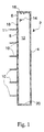
- Fig. 1 presents a cross-section of an elevator shaft 2 in side view.
- the shaft comprises a back wall 4 and a front wall 6, the latter being provided with door openings 8 at the landings 10 and 11, and side walls 12.
- the shaft extends somewhat below the lowest floor, forming a pit 20 in which the shaft equipment needed below the elevator car is installed.
- the shaft is delimited by the ceiling 16 of the shaft.
- the door openings are provided with temporary safety walls 18, which may consist of e.g. plastic plates, wooden beams or steel bars.
- the shaft is provided with supporting elements 14 fixed to the side walls of the shaft above the top floor 11, on which elements the plumbing jigs 22 can be mounted as described below in detail.
- the plumbing jig 22 (Fig. 2) is mounted using telescopic tubes 24 placed on the supporting elements 14, the tubes being adjusted to a length corresponding to the shaft width.
- the telescopic tubes 24 are attached to profiled bars comprised in the supporting elements 14.
- the plumbing jig consists of two side bars 26 which, in the depth direction of the shaft, extend from the shaft door toward the back wall of the shaft to the plane of the guide rails 28. Fixed to the door-side ends of the side bars 26 are square elbows 30, which are further attached to a front bar 32 connecting the square elbows 30 to each other.
- the square elbows are adjustably attached to the side bars and the front bar, allowing the same mounting jig to be used in elevator shafts of different dimensions.
- Attached to the front bar is a plumbing plate 34, which is provided with notches 36 located at the positions where the plumb lines for the landing door mounting brackets are to be set. Notches 36' and 36'' are for different elevators.
- Attached to the shaft-side ends of the side bars are plumbing plates 38 for the guide rails of the elevator car, the plates being provided with notches 40 for the plumb lines 43 used to plumb the guide rails 28.
- the attachment of the plumbing plates 38 to the side bars 26 can be adjusted according to the dimensions of the elevator shaft.
- a plumbing jig assembly corresponding to the configuration of the elevator shaft is set up.
- the plumb lines are dropped into the shaft and fixed to the positions marked on the plumbing plates.
- the positions of the guide rail lines are measured correspondingly and the plumb lines are fixed in place.
- the plumb lines and the corresponding positions of guide rails and landing door mounting brackets are checked. If necessary, the plumb line positions are readjusted to bring the entire shaft into alignment.
- Installation of the elevator guide rails is started from the lowest guide rail, proceeding one guide rail pair at a time up to the top.
- the positions of the counterweight guide rails are determined by means of a special gauge 60, which is used to ensure that the guide rails are installed in a straight vertical line and also that the guide rail guide surfaces are perpendicular and in alignment with the guide surfaces of other guide rails.
- the gauge comprises a bar 62 placed between the guide rails in the shaft and provided with aligning points for a plumb line 43, and a rod 64 between the counterweight guide rails 67 and 68 and a rod 66 between one 68 of the counterweight guide rails and one 28 of the car guide rails.
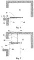
- FIGs 3, 4 and 5 illustrate different arrangements for mounting the supporting elements for the plumbing jig in the elevator shaft.
- a supporting element has been fixed to a shaft wall.
- the supporting element consists of a horizontal bar 41 whose one end is fastened to an adapter plate 42 bolted to the wall while the other end rests on an oblique supporting bar 44.
- the supporting bar is attached by its lower end to another adapter plate 46.
- the adapter plates are used to adjust the supporting element so as to bring it into a horizontal position and into alignment with another supporting element mounted on the opposite shaft wall.
- the adapter plates are placed on the shaft wall adjoining the landing, so the supporting elements are easily accessible and adjustable during installation.
- the supporting element is preferably mounted above the top floor so that it is at a suitable height for installers working on the floor and that the fixtures for all guide rails can be easily positioned by means of the plumb lines 43.
- the plumbing jig 22 is placed on and attached to the supporting elements.
- the supporting element 48 is mounted on the top floor 11, being fixed to the landing floor 50 e.g. by means of bolts 52.
- the supporting element may be fixed to other landing structures.
- the plumbing jig 22 itself may be implemented as described above.
- the supporting elements for the plumbing jig are formed from two bars 54 suspended from the ceiling 16 of the elevator shaft.
- the bars 54 are fixed to wire cables or bars 56 whose other ends are fixed to hooks 58 mounted in the shaft ceiling.
- the vertical position of the supporting elements is adjusted e.g. by means of an adjusting screw fitted at the lower end of bar 56.
- the supporting element is preferably placed at a suitable working height relative to the top floor.
- the plumbing jig 22 may be implemented as described above.
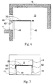
- the plumbing jig 22 In the fourth embodiment to install the plumbing jig (Fig. 6 and Fig. 7) there are mounting brackets 62, which are fixed to the door jambs 60 on the top floor 11.
- the brackets may also be fixed to the side walls if there is no front wall or they may be fixed to the edges of the front wall on the both sides of the door openings 8.
- the plumbing jig 22 can be fixed easily and the mounter does not need to stretch himself to the shaft when fixing the plumbing jig.
Landscapes
- Lift-Guide Devices, And Elevator Ropes And Cables (AREA)
- Elevator Door Apparatuses (AREA)
- Types And Forms Of Lifts (AREA)
- Indicating And Signalling Devices For Elevators (AREA)
- Cage And Drive Apparatuses For Elevators (AREA)
- Forklifts And Lifting Vehicles (AREA)
Abstract
Description
- Fig. 1
- presents an elevator shaft in lateral view,
- Fig. 2
- presents a plumbing jig in top view,
- Fig. 3
- presents an arrangement according to the invention in lateral view,
- Fig. 4
- presents another arrangement according to the invention in lateral view,
- Fig. 5
- presents a third arrangement according to the invention in lateral view,
- Fig. 6
- presents a fourth arrangement according to the invention in lateral view,
- Fig. 7
- presents a fourth arrangement according to the invention viewed from the top floor.
Claims (12)
- Method for positioning and mounting the shaft equipment (28) to be installed in an elevator shaft (2), wherein various pieces of the shaft equipment (28) are positioned using plumb lines (43) attached to a plumbing jig (22) and fixed in place after the positioning, the plumbing jig (22) being mounted via supporting elements located in the upper part of the elevator shaft (2) above the top floor (11),
characterised in thatthe supporting elements (41;42) for the plumbing jig (22) is/are mounted in a suitable height for installers working on the top floor (11), and thatthe plumb lines (43) are attached to the plumbing jig (22) working on the top floor (11). - Method for positioning and mounting the shaft equipment (28) to be installed in an elevator shaft (2), wherein various pieces of the shaft equipment (28) are positioned using plumb lines (43) attached to a plumbing jig (22) and fixed in place after the positioning, the plumbing jig (22) being mounted in the upper part of the elevator shaft (2) characterised in thata carrier (48;54) for the plumbing jig (22) is provided, which carrier is mounted on or above the top floor (11) in a suitable height for installers working on the top floor (11), and thatthe plumb lines (43) are attached to the plumbing jig (22) working on the top floor (11).
- Method as defined in claim 2, characterised in that the plumbing jig (22) is mounted on a carrier (54) suspended from the ceiling (16), said carrier (54) being mounted in place from the top floor (11).
- Method as defined in claim 2, characterised in that the plumbing jig (22) is mounted on a carrier (48) fixed to the landing (50) of the top floor (11).
- Method as defined in claim 1, characterised in that the supporting elements (41,42) are attached to the walls (12) of the elevator shaft.
- Method as defined in any one of the preceding claims, characterised in that the plumbing jig (22) is mounted to the jambs of the top floor door or to the structure of the front wall of the top floor
- Method as defined in any one of claims 1 - 6, characterised in that the shaft equipment (28) is positioned using a plumb line (43) and a gauge (62,66,67) placed between the plumb line (43) and the shaft equipment.
- Method as defined in any one of claims 1 - 7, characterised in that, to install shaft equipment (28), the shaft equipment is lifted from the bottom of the shaft (20) using the elevator car.
- Method as defined in any one of claims 1 - 8, characterised in that the plumbing jig is mounted and the plumb lines are positioned into the shaft without any scaffolds or ladders.
- Apparatus for the plumbing and installation of shaft equipment for an elevator, comprising supporting elements (41,42) being fixable to the elevator shaft (2), a plumbing jig (22) that is attachable to the supporting elements and plumb lines (43) that are suspendable from the plumbing jig and that extend into the elevator shaft (2) below the plumbing jig (22) and are used to align at least one guide rail,
characterised in that the supporting elements are mounted above the top floor (11) in a suitable height for installers working on the top floor, or
that a carrier (48;54) for the plumbing jig (22) is provided which is mounted on or above the top floor (11) in a suitable height for installers working on the top floor . - Apparatus as defined in claim 10, characterised in that the supporting elements (41;48;54) are fixable to the shaft walls (12), to a floor (11), to the shaft ceiling (16) or to the door jambs.
- Apparatus as defined in claim 10 or 11, characterised in that it comprises four plumb lines (43) and a gauge (62,66,67).
Applications Claiming Priority (3)
| Application Number | Priority Date | Filing Date | Title |
|---|---|---|---|
| FI970970A FI109291B (en) | 1997-03-07 | 1997-03-07 | Method and apparatus for installing a lift |
| FI970970 | 1997-03-07 | ||
| PCT/FI1998/000205 WO1998040303A1 (en) | 1997-03-07 | 1998-03-06 | Procedure and apparatus for the installation of an elevator |
Publications (2)
| Publication Number | Publication Date |
|---|---|
| EP0902753A1 EP0902753A1 (en) | 1999-03-24 |
| EP0902753B1 true EP0902753B1 (en) | 2002-02-06 |
Family
ID=8548357
Family Applications (1)
| Application Number | Title | Priority Date | Filing Date |
|---|---|---|---|
| EP98908136A Expired - Lifetime EP0902753B1 (en) | 1997-03-07 | 1998-03-06 | Procedure and apparatus for the installation of an elevator |
Country Status (14)
| Country | Link |
|---|---|
| US (2) | US6422352B1 (en) |
| EP (1) | EP0902753B1 (en) |
| JP (1) | JP3605417B2 (en) |
| KR (1) | KR100298032B1 (en) |
| CN (1) | CN1102909C (en) |
| AT (1) | ATE212950T1 (en) |
| AU (1) | AU725005B2 (en) |
| BR (1) | BR9805942A (en) |
| CA (1) | CA2253264C (en) |
| DE (1) | DE69803731T2 (en) |
| ES (1) | ES2169500T3 (en) |
| FI (1) | FI109291B (en) |
| RU (1) | RU2194004C2 (en) |
| WO (1) | WO1998040303A1 (en) |
Families Citing this family (35)
| Publication number | Priority date | Publication date | Assignee | Title |
|---|---|---|---|---|
| BR9805943A (en) * | 1997-03-07 | 1999-08-31 | Kone Corp | Procedure and apparatus for installing an elevator |
| FI109291B (en) * | 1997-03-07 | 2002-06-28 | Kone Corp | Method and apparatus for installing a lift |
| US7299896B1 (en) | 1998-09-29 | 2007-11-27 | Otis Elevator Company | Elevator system having drive motor located adjacent to hoistway door |
| FI4662U1 (en) * | 2000-06-08 | 2000-10-12 | Kone Corp | installation Tool |
| US6857508B2 (en) * | 2002-10-31 | 2005-02-22 | Inventio Ag | Elevator hoist machine installation apparatus |
| AU2003277477A1 (en) * | 2002-11-06 | 2004-06-07 | Lixin Sun | A detection method of lift guide rail perpendicularity and a detector for implementing this method |
| KR100944619B1 (en) * | 2004-11-16 | 2010-02-26 | 오티스 엘리베이터 컴파니 | Installing guide rails in an elevator system |
| CN101124142A (en) * | 2004-11-16 | 2008-02-13 | 奥蒂斯电梯公司 | Install guide rails in elevator systems |
| US20090097952A1 (en) * | 2005-08-30 | 2009-04-16 | Otis Elevator Company | Method and device for transporting an elevator car drive machine |
| FI119983B (en) * | 2006-05-24 | 2009-05-29 | Kone Corp | Procedure and system for mounting guides to a lift |
| EP2043938B1 (en) * | 2006-07-24 | 2012-11-28 | Otis Elevator Company | Elevators |
| FI119321B (en) * | 2006-11-02 | 2008-10-15 | Kone Corp | Procedure and system for mounting lift guides and use of the system for mounting lift guides |
| FI118644B (en) * | 2006-11-17 | 2008-01-31 | Kone Corp | Elevator installing method for use during construction of tall building, involves dismounting machine room of elevator provided with room, and converting elevator into elevator without machine room by placing hoisting machine |
| JP5040496B2 (en) * | 2007-07-20 | 2012-10-03 | 三菱電機ビルテクノサービス株式会社 | Automatic positioning apparatus and method for elevator reference template |
| US8646224B2 (en) * | 2008-09-17 | 2014-02-11 | Wurtec Elevator Products & Services | Construction apparatus |
| US8291568B2 (en) * | 2008-11-28 | 2012-10-23 | Kone Corporation | Method of installing an elevator |
| US7886454B2 (en) * | 2008-12-31 | 2011-02-15 | Kone Corporation | Elevator hoistway installation guide systems, methods and templates |
| FI121977B (en) | 2009-04-07 | 2011-06-30 | Kone Corp | Equipment and procedure for measuring an elevator shaft |
| CA2718454A1 (en) * | 2009-10-20 | 2011-04-20 | Kirk B. Gregus | Elevator work deck |
| ES2572938T3 (en) * | 2010-04-30 | 2016-06-03 | Inventio Ag | Procedure and device for installing an elevator in an elevator box |
| CN102849562B (en) * | 2011-06-30 | 2015-09-02 | 五冶集团上海有限公司 | A kind of method improving installation precision of derrick inside elevator barrel |
| EP2736829B1 (en) * | 2011-07-28 | 2015-03-18 | Inventio AG | Method and device for aligning shaft doors of a lift |
| JP2013049509A (en) * | 2011-08-30 | 2013-03-14 | Toshiba Elevator Co Ltd | Centering tool of elevator guide rail |
| EP2746211A1 (en) * | 2012-12-19 | 2014-06-25 | Inventio AG | Maintenance method for a lift |
| EP2746210A1 (en) * | 2012-12-19 | 2014-06-25 | Inventio AG | Installation method for a lift |
| CN103411508A (en) * | 2013-07-19 | 2013-11-27 | 重庆迈高电梯有限公司 | Tool for installation of landing door |
| AU2014364737B2 (en) * | 2013-12-19 | 2017-04-20 | Inventio Ag | Method for installing an elevator system, and device |
| CN106458514B (en) | 2014-06-13 | 2021-06-25 | 三菱电机株式会社 | Elevator shaft dimension measuring device and measuring method |
| DK3436390T3 (en) * | 2016-03-31 | 2020-07-27 | Inventio Ag | METHOD AND INSTALLATION DEVICE FOR CARRYING OUT AN INSTALLATION PROCESS IN AN ELEVATOR SHAFT OF AN ELEVATOR SYSTEM |
| CN107215748B (en) * | 2017-07-04 | 2020-06-23 | 东莞市鑫峰建筑机械有限公司 | Special construction hoist for hoistway and installation method thereof |
| WO2020081046A1 (en) * | 2018-10-15 | 2020-04-23 | Kone Corporation | Method and arrangement |
| US12103820B2 (en) * | 2020-11-30 | 2024-10-01 | Inventio Ag | Car floor for an elevator car and method for installing an elevator car |
| CN114187818A (en) * | 2021-12-14 | 2022-03-15 | 广东非凡教育设备有限公司 | A kind of elevator landing door structure for teaching |
| US12496256B2 (en) | 2023-12-13 | 2025-12-16 | Express Scripts Strategic Development, Inc. | Prescription drug bottle measuring device and method of use |
| JP7567075B1 (en) * | 2024-01-10 | 2024-10-15 | 東芝エレベータ株式会社 | Marker installation device for elevator measurement and elevator measurement method |
Family Cites Families (19)
| Publication number | Priority date | Publication date | Assignee | Title |
|---|---|---|---|---|
| US3601938A (en) * | 1970-01-16 | 1971-08-31 | Charles M Loomis | Universal elevator shaft entrance construction |
| US3759349A (en) * | 1972-03-13 | 1973-09-18 | Otis Elevator Co | Elevator system with temporary hoistway structure and method for use thereof |
| US3851736A (en) * | 1973-03-20 | 1974-12-03 | Westinghouse Electric Corp | Apparatus and method for installing elevator hoistway equipment |
| JPS5323447A (en) * | 1976-08-16 | 1978-03-03 | Hitachi Ltd | Method of installing elevator |
| JPS54138258A (en) * | 1978-04-19 | 1979-10-26 | Hitachi Ltd | Elevator installing method |
| US4593794A (en) * | 1984-04-23 | 1986-06-10 | Schindler Haughton Elevator Corporation | Apparatus and method for installing elevator rails |
| FR2603876B1 (en) * | 1986-09-11 | 1991-01-18 | Otis Elevator Co | PROCESS FOR THE INSTALLATION OF ELEVATOR DOORS |
| FR2623787B1 (en) * | 1987-11-27 | 1990-05-11 | Otis Elevator Co | METHOD OF MOUNTING AN ELEVATOR OR LIFT WITHIN A BUILDING, MOUNTING JIGS USED, ELEVATOR OR LIFT OBTAINED |
| US5065843A (en) * | 1990-05-16 | 1991-11-19 | Otis Elevator Company | Method for installing elevator system components |
| EP0501140B1 (en) * | 1991-03-01 | 1995-03-29 | Inventio Ag | Erecting scaffold moveable along an elevator shaft for erecting shaft equipment |
| JPH05139657A (en) * | 1991-11-20 | 1993-06-08 | Mitsubishi Electric Corp | Device for holding plumb wire for work of installing elevator |
| JPH05186160A (en) * | 1992-01-06 | 1993-07-27 | Mitsubishi Electric Corp | Elevator centering device |
| JPH05319729A (en) * | 1992-05-22 | 1993-12-03 | Toshiba Corp | Attaching work device of guide rail of elevator and attaching work method of guide rail using that device |
| JP2606052B2 (en) * | 1992-06-25 | 1997-04-30 | 三菱電機株式会社 | Upper die plate device for elevator installation |
| JP2653964B2 (en) | 1993-02-23 | 1997-09-17 | 三菱電機ビルテクノサービス株式会社 | Hoistway centering jig |
| JPH08133623A (en) * | 1994-11-07 | 1996-05-28 | Mitsubishi Electric Corp | Elevator installation template device, main ruler material and plumb line fixing tool |
| BR9805943A (en) * | 1997-03-07 | 1999-08-31 | Kone Corp | Procedure and apparatus for installing an elevator |
| FI101783B (en) * | 1997-03-07 | 1998-08-31 | Kone Corp | Method and equipment in elevator installation |
| FI109291B (en) * | 1997-03-07 | 2002-06-28 | Kone Corp | Method and apparatus for installing a lift |
-
1997
- 1997-03-07 FI FI970970A patent/FI109291B/en not_active IP Right Cessation
-
1998
- 1998-03-06 CA CA002253264A patent/CA2253264C/en not_active Expired - Lifetime
- 1998-03-06 US US09/180,355 patent/US6422352B1/en not_active Expired - Lifetime
- 1998-03-06 EP EP98908136A patent/EP0902753B1/en not_active Expired - Lifetime
- 1998-03-06 BR BR9805942-4A patent/BR9805942A/en not_active IP Right Cessation
- 1998-03-06 KR KR1019980708953A patent/KR100298032B1/en not_active Expired - Lifetime
- 1998-03-06 DE DE69803731T patent/DE69803731T2/en not_active Expired - Lifetime
- 1998-03-06 JP JP53925198A patent/JP3605417B2/en not_active Expired - Lifetime
- 1998-03-06 RU RU98121803/28A patent/RU2194004C2/en active
- 1998-03-06 ES ES98908136T patent/ES2169500T3/en not_active Expired - Lifetime
- 1998-03-06 AT AT98908136T patent/ATE212950T1/en active
- 1998-03-06 AU AU66252/98A patent/AU725005B2/en not_active Expired
- 1998-03-06 WO PCT/FI1998/000205 patent/WO1998040303A1/en not_active Ceased
- 1998-03-06 CN CN98800249A patent/CN1102909C/en not_active Expired - Lifetime
-
2002
- 2002-06-11 US US10/166,185 patent/US7137485B2/en not_active Expired - Fee Related
Also Published As
| Publication number | Publication date |
|---|---|
| CA2253264C (en) | 2003-12-30 |
| US7137485B2 (en) | 2006-11-21 |
| ATE212950T1 (en) | 2002-02-15 |
| FI109291B (en) | 2002-06-28 |
| BR9805942A (en) | 1999-08-31 |
| KR100298032B1 (en) | 2002-05-09 |
| KR20000010817A (en) | 2000-02-25 |
| CN1102909C (en) | 2003-03-12 |
| WO1998040303A1 (en) | 1998-09-17 |
| JPH11513963A (en) | 1999-11-30 |
| AU725005B2 (en) | 2000-10-05 |
| HK1018767A1 (en) | 2000-01-07 |
| JP3605417B2 (en) | 2004-12-22 |
| RU2194004C2 (en) | 2002-12-10 |
| US20020148689A1 (en) | 2002-10-17 |
| ES2169500T3 (en) | 2002-07-01 |
| DE69803731D1 (en) | 2002-03-21 |
| CA2253264A1 (en) | 1998-09-17 |
| FI970970A0 (en) | 1997-03-07 |
| DE69803731T2 (en) | 2004-04-08 |
| US6422352B1 (en) | 2002-07-23 |
| CN1219156A (en) | 1999-06-09 |
| AU6625298A (en) | 1998-09-29 |
| EP0902753A1 (en) | 1999-03-24 |
| FI970970L (en) | 1998-09-08 |
Similar Documents
| Publication | Publication Date | Title |
|---|---|---|
| AU725005B2 (en) | Procedure and apparatus for the installation of an elevator | |
| AU737295B2 (en) | Procedure and apparatus for the installation of an elevator | |
| CA2131748C (en) | An adjustable mount for elevator guide rails | |
| EP0464312B1 (en) | Method and apparatus for erecting hydraulic elevator rails | |
| US6446762B1 (en) | Elevator machine support frame mounted to hoistway wall | |
| CN1033571C (en) | Elevator hoistway working platform | |
| RU2414411C2 (en) | System of jacks for guides | |
| US20060054419A1 (en) | Elevator entrance sill structure and installation method | |
| WO2022229075A1 (en) | Suspension system for a framework structure, a method for suspending a framework structure on an exterior wall structure of a building and the use of such suspension system | |
| CN110980468A (en) | Indoor construction elevator system and dismounting method | |
| CN108584646B (en) | Assembled type additional elevator shaft structure suitable for jacking construction | |
| CN115159300A (en) | Elevator installation construction method | |
| EP0646537A1 (en) | Elevator machine room and procedure for installing it | |
| EP2706167B1 (en) | Wall bracket | |
| JPH06305657A (en) | Elevator and its elevator shaft | |
| HK1018767B (en) | Procedure and apparatus for the installation of an elevator | |
| CN219100652U (en) | Protection operation platform | |
| JP2006044843A (en) | Working bench scaffold for hoistway | |
| JPH06305656A (en) | Elevator shaft construction method | |
| JP3121516B2 (en) | Method of forming building with elevator | |
| BG113553A (en) | Modular terrace method and structure | |
| GB2291919A (en) | Worker support staging | |
| JP5146076B2 (en) | Elevator landing equipment | |
| JPH05213562A (en) | Method and apparatus for lower centering of hydraulic elevator |
Legal Events
| Date | Code | Title | Description |
|---|---|---|---|
| PUAI | Public reference made under article 153(3) epc to a published international application that has entered the european phase |
Free format text: ORIGINAL CODE: 0009012 |
|
| 17P | Request for examination filed |
Effective date: 19981130 |
|
| AK | Designated contracting states |
Kind code of ref document: A1 Designated state(s): AT BE CH DE DK ES FI FR GB GR IE IT LI LU MC NL PT SE |
|
| AX | Request for extension of the european patent |
Free format text: AL PAYMENT 981130;LT PAYMENT 981130;LV PAYMENT 981130;MK PAYMENT 981130;RO PAYMENT 981130;SI PAYMENT 981130 |
|
| 17Q | First examination report despatched |
Effective date: 19991220 |
|
| GRAG | Despatch of communication of intention to grant |
Free format text: ORIGINAL CODE: EPIDOS AGRA |
|
| GRAG | Despatch of communication of intention to grant |
Free format text: ORIGINAL CODE: EPIDOS AGRA |
|
| GRAH | Despatch of communication of intention to grant a patent |
Free format text: ORIGINAL CODE: EPIDOS IGRA |
|
| GRAH | Despatch of communication of intention to grant a patent |
Free format text: ORIGINAL CODE: EPIDOS IGRA |
|
| GRAA | (expected) grant |
Free format text: ORIGINAL CODE: 0009210 |
|
| REG | Reference to a national code |
Ref country code: GB Ref legal event code: IF02 |
|
| AK | Designated contracting states |
Kind code of ref document: B1 Designated state(s): AT BE CH DE DK ES FI FR GB GR IE IT LI LU MC NL PT SE |
|
| AX | Request for extension of the european patent |
Free format text: AL PAYMENT 19981130;LT PAYMENT 19981130;LV PAYMENT 19981130;MK PAYMENT 19981130;RO PAYMENT 19981130;SI PAYMENT 19981130 |
|
| PG25 | Lapsed in a contracting state [announced via postgrant information from national office to epo] |
Ref country code: GR Free format text: LAPSE BECAUSE OF FAILURE TO SUBMIT A TRANSLATION OF THE DESCRIPTION OR TO PAY THE FEE WITHIN THE PRESCRIBED TIME-LIMIT Effective date: 20020206 Ref country code: FI Free format text: LAPSE BECAUSE OF FAILURE TO SUBMIT A TRANSLATION OF THE DESCRIPTION OR TO PAY THE FEE WITHIN THE PRESCRIBED TIME-LIMIT Effective date: 20020206 Ref country code: BE Free format text: LAPSE BECAUSE OF FAILURE TO SUBMIT A TRANSLATION OF THE DESCRIPTION OR TO PAY THE FEE WITHIN THE PRESCRIBED TIME-LIMIT Effective date: 20020206 |
|
| REF | Corresponds to: |
Ref document number: 212950 Country of ref document: AT Date of ref document: 20020215 Kind code of ref document: T |
|
| REG | Reference to a national code |
Ref country code: CH Ref legal event code: EP |
|
| PG25 | Lapsed in a contracting state [announced via postgrant information from national office to epo] |
Ref country code: MC Free format text: LAPSE BECAUSE OF NON-PAYMENT OF DUE FEES Effective date: 20020306 Ref country code: LU Free format text: LAPSE BECAUSE OF NON-PAYMENT OF DUE FEES Effective date: 20020306 |
|
| REF | Corresponds to: |
Ref document number: 69803731 Country of ref document: DE Date of ref document: 20020321 |
|
| REG | Reference to a national code |
Ref country code: CH Ref legal event code: NV Representative=s name: R. A. EGLI & CO. PATENTANWAELTE |
|
| PG25 | Lapsed in a contracting state [announced via postgrant information from national office to epo] |
Ref country code: PT Free format text: LAPSE BECAUSE OF FAILURE TO SUBMIT A TRANSLATION OF THE DESCRIPTION OR TO PAY THE FEE WITHIN THE PRESCRIBED TIME-LIMIT Effective date: 20020506 Ref country code: DK Free format text: LAPSE BECAUSE OF FAILURE TO SUBMIT A TRANSLATION OF THE DESCRIPTION OR TO PAY THE FEE WITHIN THE PRESCRIBED TIME-LIMIT Effective date: 20020506 |
|
| ET | Fr: translation filed | ||
| REG | Reference to a national code |
Ref country code: ES Ref legal event code: FG2A Ref document number: 2169500 Country of ref document: ES Kind code of ref document: T3 |
|
| PLBE | No opposition filed within time limit |
Free format text: ORIGINAL CODE: 0009261 |
|
| STAA | Information on the status of an ep patent application or granted ep patent |
Free format text: STATUS: NO OPPOSITION FILED WITHIN TIME LIMIT |
|
| 26N | No opposition filed |
Effective date: 20021107 |
|
| REG | Reference to a national code |
Ref country code: LT Ref legal event code: MM9D Effective date: 20140306 |
|
| REG | Reference to a national code |
Ref country code: FR Ref legal event code: PLFP Year of fee payment: 18 |
|
| REG | Reference to a national code |
Ref country code: FR Ref legal event code: PLFP Year of fee payment: 19 |
|
| REG | Reference to a national code |
Ref country code: FR Ref legal event code: PLFP Year of fee payment: 20 |
|
| PGFP | Annual fee paid to national office [announced via postgrant information from national office to epo] |
Ref country code: SE Payment date: 20170321 Year of fee payment: 20 Ref country code: DE Payment date: 20170322 Year of fee payment: 20 Ref country code: CH Payment date: 20170322 Year of fee payment: 20 Ref country code: FR Payment date: 20170322 Year of fee payment: 20 Ref country code: NL Payment date: 20170321 Year of fee payment: 20 |
|
| PGFP | Annual fee paid to national office [announced via postgrant information from national office to epo] |
Ref country code: GB Payment date: 20170322 Year of fee payment: 20 Ref country code: IE Payment date: 20170321 Year of fee payment: 20 Ref country code: AT Payment date: 20170322 Year of fee payment: 20 |
|
| PGFP | Annual fee paid to national office [announced via postgrant information from national office to epo] |
Ref country code: IT Payment date: 20170324 Year of fee payment: 20 Ref country code: ES Payment date: 20170315 Year of fee payment: 20 |
|
| REG | Reference to a national code |
Ref country code: DE Ref legal event code: R071 Ref document number: 69803731 Country of ref document: DE |
|
| REG | Reference to a national code |
Ref country code: NL Ref legal event code: MK Effective date: 20180305 |
|
| REG | Reference to a national code |
Ref country code: CH Ref legal event code: PL |
|
| REG | Reference to a national code |
Ref country code: GB Ref legal event code: PE20 Expiry date: 20180305 |
|
| REG | Reference to a national code |
Ref country code: IE Ref legal event code: MK9A |
|
| REG | Reference to a national code |
Ref country code: AT Ref legal event code: MK07 Ref document number: 212950 Country of ref document: AT Kind code of ref document: T Effective date: 20180306 |
|
| PG25 | Lapsed in a contracting state [announced via postgrant information from national office to epo] |
Ref country code: IE Free format text: LAPSE BECAUSE OF EXPIRATION OF PROTECTION Effective date: 20180306 Ref country code: GB Free format text: LAPSE BECAUSE OF EXPIRATION OF PROTECTION Effective date: 20180305 |
|
| REG | Reference to a national code |
Ref country code: SE Ref legal event code: EUG |
|
| REG | Reference to a national code |
Ref country code: ES Ref legal event code: FD2A Effective date: 20211229 |
|
| PG25 | Lapsed in a contracting state [announced via postgrant information from national office to epo] |
Ref country code: ES Free format text: LAPSE BECAUSE OF EXPIRATION OF PROTECTION Effective date: 20180307 |