EP0902749B1 - Vibration reducing system for automotive vehicle - Google Patents
Vibration reducing system for automotive vehicle Download PDFInfo
- Publication number
- EP0902749B1 EP0902749B1 EP98907238A EP98907238A EP0902749B1 EP 0902749 B1 EP0902749 B1 EP 0902749B1 EP 98907238 A EP98907238 A EP 98907238A EP 98907238 A EP98907238 A EP 98907238A EP 0902749 B1 EP0902749 B1 EP 0902749B1
- Authority
- EP
- European Patent Office
- Prior art keywords
- damper
- cylinder
- vibration
- insulator
- reducing system
- Prior art date
- Legal status (The legal status is an assumption and is not a legal conclusion. Google has not performed a legal analysis and makes no representation as to the accuracy of the status listed.)
- Expired - Lifetime
Links
- 239000012212 insulator Substances 0.000 claims description 45
- NJPPVKZQTLUDBO-UHFFFAOYSA-N novaluron Chemical compound C1=C(Cl)C(OC(F)(F)C(OC(F)(F)F)F)=CC=C1NC(=O)NC(=O)C1=C(F)C=CC=C1F NJPPVKZQTLUDBO-UHFFFAOYSA-N 0.000 description 8
- 230000000694 effects Effects 0.000 description 6
- 238000009434 installation Methods 0.000 description 5
- 238000000034 method Methods 0.000 description 4
- 230000001133 acceleration Effects 0.000 description 1
- 230000005540 biological transmission Effects 0.000 description 1
- 238000010276 construction Methods 0.000 description 1
- 230000001419 dependent effect Effects 0.000 description 1
- 238000012986 modification Methods 0.000 description 1
- 230000004048 modification Effects 0.000 description 1
Images


Classifications
-
- B—PERFORMING OPERATIONS; TRANSPORTING
- B60—VEHICLES IN GENERAL
- B60K—ARRANGEMENT OR MOUNTING OF PROPULSION UNITS OR OF TRANSMISSIONS IN VEHICLES; ARRANGEMENT OR MOUNTING OF PLURAL DIVERSE PRIME-MOVERS IN VEHICLES; AUXILIARY DRIVES FOR VEHICLES; INSTRUMENTATION OR DASHBOARDS FOR VEHICLES; ARRANGEMENTS IN CONNECTION WITH COOLING, AIR INTAKE, GAS EXHAUST OR FUEL SUPPLY OF PROPULSION UNITS IN VEHICLES
- B60K5/00—Arrangement or mounting of internal-combustion or jet-propulsion units
- B60K5/12—Arrangement of engine supports
- B60K5/1208—Resilient supports
-
- F—MECHANICAL ENGINEERING; LIGHTING; HEATING; WEAPONS; BLASTING
- F16—ENGINEERING ELEMENTS AND UNITS; GENERAL MEASURES FOR PRODUCING AND MAINTAINING EFFECTIVE FUNCTIONING OF MACHINES OR INSTALLATIONS; THERMAL INSULATION IN GENERAL
- F16F—SPRINGS; SHOCK-ABSORBERS; MEANS FOR DAMPING VIBRATION
- F16F1/00—Springs
- F16F1/36—Springs made of rubber or other material having high internal friction, e.g. thermoplastic elastomers
- F16F1/38—Springs made of rubber or other material having high internal friction, e.g. thermoplastic elastomers with a sleeve of elastic material between a rigid outer sleeve and a rigid inner sleeve or pin, i.e. bushing-type
- F16F1/387—Springs made of rubber or other material having high internal friction, e.g. thermoplastic elastomers with a sleeve of elastic material between a rigid outer sleeve and a rigid inner sleeve or pin, i.e. bushing-type comprising means for modifying the rigidity in particular directions
-
- F—MECHANICAL ENGINEERING; LIGHTING; HEATING; WEAPONS; BLASTING
- F16—ENGINEERING ELEMENTS AND UNITS; GENERAL MEASURES FOR PRODUCING AND MAINTAINING EFFECTIVE FUNCTIONING OF MACHINES OR INSTALLATIONS; THERMAL INSULATION IN GENERAL
- F16F—SPRINGS; SHOCK-ABSORBERS; MEANS FOR DAMPING VIBRATION
- F16F7/00—Vibration-dampers; Shock-absorbers
- F16F7/10—Vibration-dampers; Shock-absorbers using inertia effect
- F16F7/104—Vibration-dampers; Shock-absorbers using inertia effect the inertia member being resiliently mounted
- F16F7/108—Vibration-dampers; Shock-absorbers using inertia effect the inertia member being resiliently mounted on plastics springs
-
- B—PERFORMING OPERATIONS; TRANSPORTING
- B60—VEHICLES IN GENERAL
- B60K—ARRANGEMENT OR MOUNTING OF PROPULSION UNITS OR OF TRANSMISSIONS IN VEHICLES; ARRANGEMENT OR MOUNTING OF PLURAL DIVERSE PRIME-MOVERS IN VEHICLES; AUXILIARY DRIVES FOR VEHICLES; INSTRUMENTATION OR DASHBOARDS FOR VEHICLES; ARRANGEMENTS IN CONNECTION WITH COOLING, AIR INTAKE, GAS EXHAUST OR FUEL SUPPLY OF PROPULSION UNITS IN VEHICLES
- B60K5/00—Arrangement or mounting of internal-combustion or jet-propulsion units
- B60K5/12—Arrangement of engine supports
- B60K5/1208—Resilient supports
- B60K5/1216—Resilient supports characterised by the location of the supports relative to the motor or to each other
Definitions
- the present invention relates to a vibration reducing system for automotive vehicles. More specifically, the present invention relates to a vibration reducing system which is disposed between an engine and a vehicle body, and which is adapted to reduce noise and vibration transmitted from the engine to the vehicle body.
- a vibration reducing system according to the preamble of claim 1 is known from US-4,456,213.
- a further object of the present invention to provide a vibration reducing system for an automotive vehicle which will reduce the vibration and the associated noise, even if the mass of the vibration damper is relatively small.
- Figs. 1 and 2 show a vibration reducing system, which in this instance, merely by way of example, relates to a vibration reducing system which is provided between the power unit that is mounted on the vehicle body in a manner wherein it is disposed on an engine on the right side of the vehicle, and oriented in a lateral direction with respect to a side member of the vehicle.
- the reference numeral 1 denotes a vibration reducing system disposed between an engine 2 of a power unit and side member 3 of a vehicle body.
- the vibration reducing system 1 provides an attachment part 5 which is secured to the engine 2, an insulator 9 which includes an elastic insulator member, which is referred to as a first elastic member 8 disposed between an outer insulator cylinder, referred to hereinafter as a first outer cylinder 6 and an inner insulator cylinder, referred to hereinafter as a first inner cylinder 7 and which is secured to the side member 3, a connection part 11 which includes a pin 10 fitted into an inner surface of the first inner cylinder 7, and a dynamic damper 12 connected to the insulator 9 at a side which is distal from engine 2.
- the attachment part 5 includes a base plate 14 connected to the right side of the engine 2 in a lateral direction by a bolt 13, and a pedestal 15 which horizontally extends to the right of the vehicle in a lateral direction from an upper end of the base plate 14.
- An upper surface of the pedestal 15 is a flat surface.
- Plural bolt holes (not shown), for securing the connection part 11 to the pedestal 15, are formed in this upper surface.
- the insulator 9 includes the first outer cylinder 6, and a first inner cylinder 7 which is coaxially disposed in the first outer cylinder 6. Both ends of the first inner cylinder 7 project out beyond the respective limits of the first outer cylinder 6.
- the first elastic member 8 is bonded between an outer surface of the first inner cylinder 7 and an inner surface of the first outer cylinder 6.
- Arc shaped hollows or openings 16a, 16b are formed at an upper lower side of the first inner cylinder 7.
- Plate masses 17 are disposed in the elastomeric member so as to extend between the hollows or openings 16a, 16b in the manner illustrated in Fig. 1. Therefore, it is possible to make the first elastic member 8 is stronger in longitudinal direction than in a vertical direction, which reduces resonance frequency of the vibration of the vehicle.
- a flange 6a for securing the insulator 9 to the side member 3 is connected to both sides of an under part of the first outer cylinder 6.
- the flange 6 is secured to the side member 3 by bolts 18.
- the insulator 9 is disposed to the right side of the pedestal 15 and oriented so that its axis extends in a lateral direction of the vehicle.
- connection part 11 which is formed so as to have a triangular shape as seen in plan view, is secured to an upper surface of the pedestal 15 with one side facing to the side member 3.
- Plural bolt holes 19a are formed in the connection part 11 corresponding to the above mentioned the bolt hole of the pedestal 15, the connection part 11 is secured to the pedestal 15 by screwing bolts 19b, which are inserted into the bolt holes 19a, and the bolt holes of the pedestal 15.
- the dynamic damper 12 has an inner damper cylinder, referred to hereinafter as a second inner cylinder 21, and elastic damper member, referred to hereinafter as a second elastic member which is bonded to an outer surface of the second inner cylinder 21, an outer damper cylinder, which is referred to hereinafter as a second outer cylinder 20 which is bonded to an outer surface of the second elastic member 22, and a mass 23 which is fitted on an outer surface of the second outer cylinder 20.
- a boss 24, which defines another mass, which is of a cylindrical shape and which has a coaxial bore, is disposed within the second inner cylinder 21.
- the boss 24 has a projection 24a which fits into a small diameter pit or bore 7a formed in an end surface of the first inner cylinder 7 which faces away from the engine 2, for preventing rotation of the dynamic damper 12.
- the dynamic damper 12 is coaxially secured to the outboard tip of the pin 10 by fitting the projection 24a of the boss 24 into the pit 7a and thus connects coaxial end surfaces of the boss 24 and the first inner cylinder 7 together. This is followed by disposing a bolt 25 through the bore of the boss 24 and screwing a bolt 25 into the threaded hole 10a, which is formed at the tip of the pin 10.
- the boss 24 which is fitted on the inner surface of the second inner cylinder 21, functions as a mass damper, and is located in a position wherein it is possible to obtain adequate vibration and noise reduction even though the mass 23 is small. Further, the relatively small size of the boss 24 enables the dynamic damper 12 to be connected to the insulator 9 in a manner which renders the arrangement compact and allows for a saving in space.
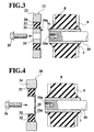
- FIG. 4 An embodiment shown in Fig. 4 indicates that a dynamic damper 30 is secured to the tip of the pin 10 by a bolt.
- the dynamic damper 30 has a second inner cylinder 32, a second elastic member 33 which is bonded on an outer surface of the second inner cylinder 32, a second outer cylinder 31 which is bonded on an outer surface of the second elastic member 33, and a mass 34 which is fitted on an outer surface of the second outer cylinder 31.
- the second inner cylinder 32 has a securing part 32a on the side of the second inner cylinder facing the pin 10.
- the securing part 32a has a bolt hole 35 at its center.
- the dynamic damper 30 is coaxially secured to the tip of the pin 10 by disposing the securing part 32a of the second inner cylinder 32 coaxially against the first inner cylinder 7, and then screwing a bolt 36 into the threaded hole 10a which is formed at the tip of the pin 10 via the bolt hole 35 of the securing part 32a.
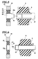
- the embodiment shown in Fig. 5 features a dynamic damper 40 secured to a side of the first inner cylinder 7 of the insulator 9 which is distal from the engine 2, by way of a force fitting technique.
- the dynamic damper 40 has a second inner cylinder 42, a second elastic member 43 which is bonded on an outer surface of the second inner cylinder 42, a second outer cylinder 41 which is bonded on an outer surface of the second elastic member 43, and a mass 44 which is fitted onto an outer surface of the second outer cylinder 41.
- a column shaped mass 45 whose diameter is approximately the same as the diameter of the first inner cylinder 7 of the insulator 9, is force fitted into an inner surface of the second inner cylinder 42.
- the mass 45 has a small diameter part 46 which protrudes from an edge of the second inner cylinder 42 at an end facing a tip of pin 47.
- This small diameter part has a diameter which is a little larger than an inner diameter of the first inner cylinder 7 of the insulator 9.
- the tip of the pin 47 is shortened on the engine 2 side at least by the length of the small diameter part 46.
- the dynamic damper 40 is coaxially connected to an end of the first inner cylinder 7 which is distal from the engine 2 by fitting the small diameter part 46 into the first inner cylinder 7. Then, a shoulder 45a, which is formed between an outer diameter of the mass 45 and the small diameter part 46, is caused to abut the edge of the first inner cylinder 7 which is distal from the engine 2.
- the mass 45 functions as a mass damper in the same manner as mass 24 shown in Fig. 3, and it is possible to obtain that same meritorious effect as the embodiment shown in Fig. 3. Additionally, it is possible to facilitate attachment of the dynamic damper 40 to the insulator 9 by attachment techniques other than attachment by bolt.
- FIG. 6 Another embodiment shown in Fig. 6 features the dynamic damper 50 being secured to the first inner cylinder 55 of the insulator 9 at a side which is distal from the engine 2 using a fitting technique.
- the dynamic damper 50 has a second inner cylinder 52, a second elastic member 53 which is bonded on an outer surface of the second inner cylinder 52, a second outer cylinder 51 which is bonded on an outer surface of the second elastic member 53, and a mass 54 which is fitted on an outer surface of the second outer cylinder 51.
- the second inner cylinder 52 has a cap-like configuration with a bottom plate 52a. The inner diameter of this cap-like inner cylinder 52 is a little smaller than an outer diameter of the first inner cylinder 55 of the insulator 9.
- the bottom plate 55a of the first inner cylinder 55 is formed to correspond to the bottom plate 52a of the second inner cylinder 52.
- the dynamic damper 50 is coaxially secured to an end of the first inner cylinder 55, which is distal from the engine 2, by fitting the second inner cylinder 52 onto the outer surface of the first inner cylinder 55 until the bottom plate 52a abuts against the bottom plate 55a.
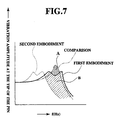
- Fig. 7 shows the amplitude frequency characteristics of the vibration which occurs at the tip of the pin 10.
- characteristics are derived using the first embodiment which is equipped with the dynamic damper 30 having the structure shown in Fig. 4, and is indicated by the trace denoted by "first embodiment", while the characteristic trace which is derived using the embodiment which is equipped the dynamic damper 12 having the structure shown in Fig. 3, is denoted by "second embodiment".
- the characteristics of a vibration reducing device which is not equipped a dynamic damper is provided as a control and labelled “comparison”.
- the data for the first and second embodiments were obtained under the same experimental conditions and differed only in the manner of dynamic damper attachment.
- the “comparison” is different from the first and second embodiments due to the absence of a dynamic damper.
- Fig. 7 shows that the first embodiment has an effect of reducing the vibration amplitude denoted by the hatched portion B as compared with the comparison (denoted by hatched portion A), while the second embodiment, which additionally includes the effect of the mass damper, has an effect of reducing the vibration amplitude which is denoted by the broken line trace.
- the vibration damper is not limited to dynamic dampers, and it is possible to alternatively use a mass damper arrangement in lieu of a dynamic type of arrangement.
- the rotation preventing device is not limited to the combination of the projection 24a which is formed on the end surface of the boss 24 and the pit 7a which is formed at the end surface of the boss 24 and the pit 7a which is formed at the end surface of the first inner cylinder 7, as it is possible to form the projection on the end surface of the second inner cylinder.
- a vibration reducing system for an automotive vehicle which facilitates installation of the vibration damper to the vibration reducing system.
- This vibration reducing system can minimize the space required for installation of the vibration damper.
- This vibration reducing system can reduce the vibration and the associated noise, even if the mass of the vibration damper is relatively small.
Landscapes
- Engineering & Computer Science (AREA)
- General Engineering & Computer Science (AREA)
- Mechanical Engineering (AREA)
- Chemical & Material Sciences (AREA)
- Combustion & Propulsion (AREA)
- Transportation (AREA)
- Vibration Prevention Devices (AREA)
- Arrangement Or Mounting Of Propulsion Units For Vehicles (AREA)
Description
Claims (10)
- A vibration reducing system for automotive vehicles having a power unit comprising:characterized in thatan attachment part (5) connected to the power unit (2);a vibration insulator (9) connected to a vehicle body and a vibration damper (12);said insulator (9) having an inner insulator cylinder (7; 55), an elastic insulator member (8) which is connected to an outer surface of said inner insulator cylinder (7, 55), and an outer insulator cylinder (6) which is connected to an outer surface of said elastic insulator member (8) and being connected to a vehicle body;a connection part (11) having a pin (10) which is fitted onto the inner insulator cylinder (7, 55) and connected to said attachment part (5);said vibration damper (12) being arranged coaxially to said pin (10) and connected to said insulator (9) at a site distal from the power unit (2);
said vibration damper (12) comprises an inner damper cylinder (21, 32, 42, 52) which is coaxial to said pin (10), an elastic damper member (22, 33, 43. 53) which is connected to an outer surface of said inner damper cylinder (21, 32, 42, 52), which is coaxial to said pin (10), an outer damper cylinder (20, 31, 41, 51) which is connected to an outer surface of said elastic damper member (22, 33, 43, 53), and a mass (23, 34, 44, 54) which is connected to an outer surface of said outer damper cylinder (20, 31, 41, 51). - A vibration reducing system as defined in claim 1, characterized in that said vibration damper (12) is connected to said pin (10) by a securing device.
- A vibration reducing system as defined in claim 2, characterized in that said securing device comprises a bolt (25) and a threaded hole (10a) formed in a center of said pin (10).
- A vibration reducing system as defined in claim 3, characterized in that said vibration damper (12) further comprises a boss (24) which is fitted to an inner surface of said inner damper cylinder (21), and the vibration damper (12) is connected to the pin (10) by securing the bolt (25) to the threaded hole (10a) of the pin (10) via a through hole (35) which is formed at a center of the boss (24).
- A vibration reducing system as defined in claim 3, characterized in that said inner damper cylinder (32) has a securing part (32a) which is formed at one end of the inner damper cylinder (32) and the vibration damper (30) is connected to the pin (10) by securing a bolt (36) to the threaded hole (10a) of the pin (10) via a through hole (35) which is formed at a center of the securing part (32).
- A vibration reducing system as defined in claim 1, characterized in that said inner damper cylinder (42) has a fitting part, said vibration damper (40) is connected to said inner insulator cylinder (7) by connection of said fitting part to the inner insulator cylinder (7).
- A vibration reducing system as claimed in claim 6, characterized in that said fitting part is formed by a cylindrical column (46) which is fitted to an inner surface of the inner damper cylinder (42) at one end thereof, and said vibration damper (40) is connected to said inner insulator cylinder (7) by fitting the other end of said cylindrical column (46) into an inner surface of said inner insulator cylinder (7).
- A vibration reducing system as claimed in claim 6, characterized in that said inner damper cylinder (52) has a bottom plate (52a) which is formed at the other end of the inner damper cylinder (52), said fitting part is formed by said bottom plate (52a) and the inner surface of the inner damper cylinder (52), and said vibration damper (50) is connected to said inner insulator cylinder (55) by fitting an inner surface of said fitting part on an outer surface of said inner insulator cylinder (55).
- A vibration reducing system as claimed in claim 1, characterized by a rotation preventing device which prevents relative rotation between the insulator (9) and the vibration damper (12, 30, 40, 50).
- A vibration reducing system as claimed in claim 9, characterized in that said rotation preventing device couples a projection (24a) and a pit (7a) which are formed at surfaces of the insulator (9) and the vibration damper (12).
Applications Claiming Priority (4)
| Application Number | Priority Date | Filing Date | Title |
|---|---|---|---|
| JP07234297A JP3503405B2 (en) | 1997-03-25 | 1997-03-25 | Anti-vibration device |
| JP7234297 | 1997-03-25 | ||
| JP72342/97 | 1997-03-25 | ||
| PCT/JP1998/001090 WO1998042528A1 (en) | 1997-03-25 | 1998-03-16 | Vibration reducing system for automotive vehicle |
Publications (2)
| Publication Number | Publication Date |
|---|---|
| EP0902749A1 EP0902749A1 (en) | 1999-03-24 |
| EP0902749B1 true EP0902749B1 (en) | 2002-07-10 |
Family
ID=13486539
Family Applications (1)
| Application Number | Title | Priority Date | Filing Date |
|---|---|---|---|
| EP98907238A Expired - Lifetime EP0902749B1 (en) | 1997-03-25 | 1998-03-16 | Vibration reducing system for automotive vehicle |
Country Status (9)
| Country | Link |
|---|---|
| US (1) | US6321890B1 (en) |
| EP (1) | EP0902749B1 (en) |
| JP (1) | JP3503405B2 (en) |
| KR (1) | KR100304498B1 (en) |
| CN (1) | CN1109614C (en) |
| DE (1) | DE69806454T2 (en) |
| MY (1) | MY120229A (en) |
| TW (1) | TW358782B (en) |
| WO (1) | WO1998042528A1 (en) |
Cited By (1)
| Publication number | Priority date | Publication date | Assignee | Title |
|---|---|---|---|---|
| DE10253767A1 (en) * | 2002-11-19 | 2004-06-09 | Daimlerchrysler Ag | Vibration absorbing carrying structure for engine of vehicle, comprising elastic carrying arm between base and rubber sleeve |
Families Citing this family (46)
| Publication number | Priority date | Publication date | Assignee | Title |
|---|---|---|---|---|
| GB9912209D0 (en) * | 1998-12-24 | 1999-07-28 | Btr Industries Ltd | Resilent bush |
| JP4569719B2 (en) * | 2000-02-10 | 2010-10-27 | Nok株式会社 | Electromagnetic clutch coupling |
| JP4642981B2 (en) * | 2000-08-30 | 2011-03-02 | 株式会社ブリヂストン | Dynamic damper |
| KR100388191B1 (en) * | 2000-09-06 | 2003-06-19 | 기아자동차주식회사 | A structure for securing power train at a proper position |
| US7284527B2 (en) * | 2003-04-08 | 2007-10-23 | Freudenberg-Nok General Partnership | Tuned vibration absorber |
| KR100514891B1 (en) * | 2003-11-07 | 2005-09-14 | 현대자동차주식회사 | roll rod for vehicle |
| EP1580057B1 (en) * | 2004-03-24 | 2013-04-24 | Nissan Motor Company Limited | Power train supporting apparatus and method for automotive vehicle |
| DE102004014889A1 (en) * | 2004-03-26 | 2005-10-13 | Bayerische Motoren Werke Ag | Vibration-damping mounting of a component |
| JP4421500B2 (en) * | 2005-03-23 | 2010-02-24 | 倉敷化工株式会社 | Vibration isolator |
| US7644911B2 (en) * | 2005-09-22 | 2010-01-12 | The Pullman Company | Isolator |
| US7753166B2 (en) * | 2005-12-08 | 2010-07-13 | Windsor Machine & Stamping Ltd | Resonant frequency adjustor and method of utilizing the same |
| KR100969690B1 (en) * | 2006-03-27 | 2010-07-14 | 미쯔이 죠센 가부시키가이샤 | Dynamic damper |
| JP4777867B2 (en) | 2006-12-04 | 2011-09-21 | 株式会社ブリヂストン | Anti-vibration support device |
| WO2008136325A1 (en) * | 2007-04-26 | 2008-11-13 | Bridgestone Corporation | Vibration-proof device |
| JP4722883B2 (en) * | 2007-06-20 | 2011-07-13 | 山下ゴム株式会社 | Torque rod |
| JP4801680B2 (en) * | 2008-01-17 | 2011-10-26 | ダイハツ工業株式会社 | Power unit support structure |
| JP5185684B2 (en) * | 2008-04-25 | 2013-04-17 | オリンパスイメージング株式会社 | Driving device and imaging device |
| US8215444B2 (en) * | 2009-07-09 | 2012-07-10 | Ford Global Technologies | Roll restrictor system for an automotive powertrain |
| KR101184281B1 (en) * | 2010-11-30 | 2012-09-21 | 기아자동차주식회사 | Roll-rod for vehicle |
| TWI435813B (en) * | 2011-06-28 | 2014-05-01 | Metal Ind Res & Dev Ct | Electric vehicle power module fixed bracket |
| KR101738018B1 (en) * | 2011-08-19 | 2017-05-19 | 현대자동차주식회사 | Structure of roll-rod for subframe |
| DE112013002625A5 (en) * | 2012-05-22 | 2015-05-07 | Schaeffler Technologies Gmbh & Co. Kg | Vibration damper, in particular a piston rod damper for a motor vehicle |
| CN103213493B (en) * | 2013-05-03 | 2016-01-20 | 无锡市中捷减震器有限公司 | Speed changing box support shock absorption device |
| EP3094451B1 (en) * | 2014-01-14 | 2023-06-07 | Temple Allen Holdings LLC | Reduced-vibration surface treatment device |
| KR101519285B1 (en) * | 2014-01-22 | 2015-05-11 | 현대자동차주식회사 | Torque rod for vehicle |
| CN104589992B (en) * | 2015-01-26 | 2017-01-18 | 安徽江淮汽车股份有限公司 | Suspension structure |
| CA2984107A1 (en) | 2015-05-11 | 2016-11-17 | Lord Corporation | Damping devices, systems and methods for hollow shafts, struts, and beams with bending modes |
| GB2540579B (en) * | 2015-07-22 | 2020-03-18 | Ford Global Tech Llc | A component mount |
| KR101845418B1 (en) * | 2015-12-11 | 2018-05-18 | 현대자동차주식회사 | Structure of Mounting bracket |
| CN106090121A (en) * | 2016-06-30 | 2016-11-09 | 奇瑞商用车(安徽)有限公司 | Mounting vibration vibration absorbing structure |
| GB2550668B (en) * | 2017-03-29 | 2021-12-22 | Ford Global Tech Llc | Roll restrictor system for an automotive powertrain |
| US10378606B2 (en) * | 2017-06-30 | 2019-08-13 | GM Global Technology Operations LLC | Selectively tunable vibration absorber for a vehicle |
| KR102394805B1 (en) * | 2017-11-24 | 2022-05-04 | 현대자동차주식회사 | Sub-roll rod device for mounting power train of vehicle |
| CN108312823B (en) * | 2018-01-11 | 2019-11-29 | 浙江零跑科技有限公司 | A kind of electronic automobile-used two-stage vibration reduction suspending device |
| JP6836539B2 (en) * | 2018-04-11 | 2021-03-03 | 本田技研工業株式会社 | Drive source support structure |
| EP3653420B1 (en) * | 2018-11-16 | 2022-06-22 | Liebherr-Components Colmar SAS | Trunnion mount for mounting an engine |
| DK3656593T3 (en) | 2018-11-16 | 2022-11-28 | Liebherr Components Colmar Sas | Pin suspension for suspending an engine |
| DE102019206519B4 (en) * | 2019-05-07 | 2021-02-25 | Audi Ag | Unit storage in a vehicle |
| DE102019111905A1 (en) * | 2019-05-08 | 2020-11-12 | Bayerische Motoren Werke Aktiengesellschaft | Carrying device for a motor vehicle and a mounting arrangement for a drive motor on a carrier element of a motor vehicle |
| CN111168373B (en) * | 2019-12-23 | 2024-02-27 | 宁波福尔达智能科技股份有限公司 | Automatic assembling device for vehicle interior handle |
| US11370286B2 (en) | 2020-03-23 | 2022-06-28 | Karma Automotive Llc | System for vehicle noise and vibration reduction |
| CN114475200B (en) * | 2020-10-23 | 2025-09-23 | 现代自动车株式会社 | Modular mounting structure and assembly method for manufacturing vehicles |
| US11472280B2 (en) * | 2021-01-07 | 2022-10-18 | GM Global Technology Operations LLC | Conical mount with rotating radial snubber assembly |
| US12214665B2 (en) * | 2021-11-30 | 2025-02-04 | Nissan North America, Inc. | Vibration dampening engine mount and modular vibration dampening engine mount system |
| KR102666342B1 (en) * | 2021-12-28 | 2024-05-17 | 주식회사 대흥알앤티 | Modular type mount for vehicle |
| CN116788358A (en) * | 2023-06-28 | 2023-09-22 | 奇瑞汽车股份有限公司 | Method and device for solving PHEV automobile gurgling sound |
Family Cites Families (7)
| Publication number | Priority date | Publication date | Assignee | Title |
|---|---|---|---|---|
| DE2632574C2 (en) | 1976-07-20 | 1984-01-19 | Mtu Motoren- Und Turbinen-Union Friedrichshafen Gmbh, 7990 Friedrichshafen | Device for damping vibrations on internal combustion engines |
| JPS56108307A (en) | 1980-02-01 | 1981-08-27 | Nissan Motor Co Ltd | Device for supporting engine |
| JPS56124513A (en) * | 1980-02-29 | 1981-09-30 | Nissan Motor Co Ltd | Mounting device of engine |
| US4456213A (en) | 1980-09-24 | 1984-06-26 | Nissan Motor Company, Limited | Engine mounting structure |
| JPH0630500Y2 (en) * | 1988-07-29 | 1994-08-17 | サンデン株式会社 | Vibration reduction device for vehicle air conditioner compressor |
| IT1237779B (en) * | 1989-11-20 | 1993-06-17 | Pirelli Sistemi Antivibranti | ENGINE SUPPORT. |
| JPH09263143A (en) | 1996-03-28 | 1997-10-07 | Mazda Motor Corp | Dynamic damper mounting structure |
-
1997
- 1997-03-25 JP JP07234297A patent/JP3503405B2/en not_active Expired - Fee Related
-
1998
- 1998-03-16 WO PCT/JP1998/001090 patent/WO1998042528A1/en not_active Ceased
- 1998-03-16 DE DE69806454T patent/DE69806454T2/en not_active Expired - Fee Related
- 1998-03-16 CN CN98800359A patent/CN1109614C/en not_active Expired - Fee Related
- 1998-03-16 KR KR1019980709654A patent/KR100304498B1/en not_active Expired - Fee Related
- 1998-03-16 EP EP98907238A patent/EP0902749B1/en not_active Expired - Lifetime
- 1998-03-16 US US09/180,610 patent/US6321890B1/en not_active Expired - Fee Related
- 1998-03-19 TW TW087104083A patent/TW358782B/en not_active IP Right Cessation
- 1998-03-24 MY MYPI98001265A patent/MY120229A/en unknown
Cited By (2)
| Publication number | Priority date | Publication date | Assignee | Title |
|---|---|---|---|---|
| DE10253767A1 (en) * | 2002-11-19 | 2004-06-09 | Daimlerchrysler Ag | Vibration absorbing carrying structure for engine of vehicle, comprising elastic carrying arm between base and rubber sleeve |
| DE10253767B4 (en) * | 2002-11-19 | 2006-12-14 | Daimlerchrysler Ag | Oscillably movable mounting of an aggregate on a supporting structure |
Also Published As
| Publication number | Publication date |
|---|---|
| DE69806454T2 (en) | 2002-11-21 |
| US6321890B1 (en) | 2001-11-27 |
| CN1109614C (en) | 2003-05-28 |
| EP0902749A1 (en) | 1999-03-24 |
| MY120229A (en) | 2005-09-30 |
| WO1998042528A1 (en) | 1998-10-01 |
| DE69806454D1 (en) | 2002-08-14 |
| KR100304498B1 (en) | 2001-11-22 |
| JP3503405B2 (en) | 2004-03-08 |
| TW358782B (en) | 1999-05-21 |
| JPH10267084A (en) | 1998-10-06 |
| KR20000016087A (en) | 2000-03-25 |
| CN1220634A (en) | 1999-06-23 |
Similar Documents
| Publication | Publication Date | Title |
|---|---|---|
| EP0902749B1 (en) | Vibration reducing system for automotive vehicle | |
| US5636826A (en) | Vibration control device | |
| KR100405359B1 (en) | Vehicle Engine Mount | |
| JP4028659B2 (en) | Anti-vibration rubber mounting structure | |
| US20050225015A1 (en) | Anti-vibration device | |
| JPH08326811A (en) | Vibration control device | |
| US20070145228A1 (en) | Bracket fixing structure | |
| JP3613928B2 (en) | Engine mount device | |
| JPH09240290A (en) | Anti-vibration device for power unit | |
| KR100210304B1 (en) | Engine mounting for a vehicle | |
| JP3760553B2 (en) | engine | |
| JPH11147420A (en) | Anti-vibration device | |
| JP3589474B2 (en) | Anti-vibration structure | |
| KR19980062112U (en) | Engine mounting of a car | |
| KR100446058B1 (en) | The Conclusion Structure of Mulitbox | |
| JP2591156B2 (en) | Mounting structure of wiper motor for automobile | |
| GB2340794A (en) | Subframe mounting | |
| KR200206513Y1 (en) | Insulators for Engine Mounts | |
| KR100387446B1 (en) | Structure for installing of crash pad | |
| KR100254341B1 (en) | Block engine mount | |
| KR19980078378A (en) | Automotive engine mounting | |
| JPH0966858A (en) | Body structure of vehicle with frame | |
| KR19980023220A (en) | Cable Bracket Dustproof Structure of Transmission | |
| KR20010059831A (en) | mounting structure of steering column for automobile | |
| KR19980049687A (en) | Automotive Transmission Mounting |
Legal Events
| Date | Code | Title | Description |
|---|---|---|---|
| PUAI | Public reference made under article 153(3) epc to a published international application that has entered the european phase |
Free format text: ORIGINAL CODE: 0009012 |
|
| 17P | Request for examination filed |
Effective date: 19981111 |
|
| AK | Designated contracting states |
Kind code of ref document: A1 Designated state(s): DE GB |
|
| 17Q | First examination report despatched |
Effective date: 20000719 |
|
| GRAG | Despatch of communication of intention to grant |
Free format text: ORIGINAL CODE: EPIDOS AGRA |
|
| GRAG | Despatch of communication of intention to grant |
Free format text: ORIGINAL CODE: EPIDOS AGRA |
|
| GRAH | Despatch of communication of intention to grant a patent |
Free format text: ORIGINAL CODE: EPIDOS IGRA |
|
| GRAH | Despatch of communication of intention to grant a patent |
Free format text: ORIGINAL CODE: EPIDOS IGRA |
|
| GRAA | (expected) grant |
Free format text: ORIGINAL CODE: 0009210 |
|
| AK | Designated contracting states |
Kind code of ref document: B1 Designated state(s): DE GB |
|
| REG | Reference to a national code |
Ref country code: GB Ref legal event code: FG4D |
|
| REF | Corresponds to: |
Ref document number: 69806454 Country of ref document: DE Date of ref document: 20020814 |
|
| PLBE | No opposition filed within time limit |
Free format text: ORIGINAL CODE: 0009261 |
|
| STAA | Information on the status of an ep patent application or granted ep patent |
Free format text: STATUS: NO OPPOSITION FILED WITHIN TIME LIMIT |
|
| 26N | No opposition filed |
Effective date: 20030411 |
|
| REG | Reference to a national code |
Ref country code: GB Ref legal event code: 746 Effective date: 20071227 |
|
| PGFP | Annual fee paid to national office [announced via postgrant information from national office to epo] |
Ref country code: GB Payment date: 20090311 Year of fee payment: 12 |
|
| PGFP | Annual fee paid to national office [announced via postgrant information from national office to epo] |
Ref country code: DE Payment date: 20090313 Year of fee payment: 12 |
|
| GBPC | Gb: european patent ceased through non-payment of renewal fee |
Effective date: 20100316 |
|
| PG25 | Lapsed in a contracting state [announced via postgrant information from national office to epo] |
Ref country code: DE Free format text: LAPSE BECAUSE OF NON-PAYMENT OF DUE FEES Effective date: 20101001 |
|
| PG25 | Lapsed in a contracting state [announced via postgrant information from national office to epo] |
Ref country code: GB Free format text: LAPSE BECAUSE OF NON-PAYMENT OF DUE FEES Effective date: 20100316 |