EP0902494B1 - Monoblock Batterie mit Thermischekontrollanordnung - Google Patents
Monoblock Batterie mit Thermischekontrollanordnung Download PDFInfo
- Publication number
- EP0902494B1 EP0902494B1 EP98402259A EP98402259A EP0902494B1 EP 0902494 B1 EP0902494 B1 EP 0902494B1 EP 98402259 A EP98402259 A EP 98402259A EP 98402259 A EP98402259 A EP 98402259A EP 0902494 B1 EP0902494 B1 EP 0902494B1
- Authority
- EP
- European Patent Office
- Prior art keywords
- transverse wall
- battery according
- piece battery
- piece
- cover
- Prior art date
- Legal status (The legal status is an assumption and is not a legal conclusion. Google has not performed a legal analysis and makes no representation as to the accuracy of the status listed.)
- Expired - Lifetime
Links
- 239000012530 fluid Substances 0.000 claims description 13
- 238000005192 partition Methods 0.000 claims description 10
- 239000004033 plastic Substances 0.000 claims description 8
- 229920003023 plastic Polymers 0.000 claims description 8
- 239000000463 material Substances 0.000 claims description 7
- 239000012809 cooling fluid Substances 0.000 claims 1
- 238000003466 welding Methods 0.000 description 6
- 239000004743 Polypropylene Substances 0.000 description 5
- 238000001816 cooling Methods 0.000 description 5
- 229920001155 polypropylene Polymers 0.000 description 5
- PPBRXRYQALVLMV-UHFFFAOYSA-N Styrene Chemical compound C=CC1=CC=CC=C1 PPBRXRYQALVLMV-UHFFFAOYSA-N 0.000 description 4
- 239000013529 heat transfer fluid Substances 0.000 description 4
- LYCAIKOWRPUZTN-UHFFFAOYSA-N Ethylene glycol Chemical compound OCCO LYCAIKOWRPUZTN-UHFFFAOYSA-N 0.000 description 3
- 239000003792 electrolyte Substances 0.000 description 3
- 239000007788 liquid Substances 0.000 description 3
- 238000007726 management method Methods 0.000 description 3
- 229910052751 metal Inorganic materials 0.000 description 3
- 239000002184 metal Substances 0.000 description 3
- -1 polypropylene Polymers 0.000 description 3
- NLHHRLWOUZZQLW-UHFFFAOYSA-N Acrylonitrile Chemical compound C=CC#N NLHHRLWOUZZQLW-UHFFFAOYSA-N 0.000 description 2
- KAKZBPTYRLMSJV-UHFFFAOYSA-N Butadiene Chemical compound C=CC=C KAKZBPTYRLMSJV-UHFFFAOYSA-N 0.000 description 2
- PXHVJJICTQNCMI-UHFFFAOYSA-N Nickel Chemical compound [Ni] PXHVJJICTQNCMI-UHFFFAOYSA-N 0.000 description 2
- 238000004026 adhesive bonding Methods 0.000 description 2
- 239000002826 coolant Substances 0.000 description 2
- 229920001577 copolymer Polymers 0.000 description 2
- 235000021183 entrée Nutrition 0.000 description 2
- 239000007789 gas Substances 0.000 description 2
- 229920002492 poly(sulfone) Polymers 0.000 description 2
- 238000007789 sealing Methods 0.000 description 2
- 229910000838 Al alloy Inorganic materials 0.000 description 1
- WHXSMMKQMYFTQS-UHFFFAOYSA-N Lithium Chemical compound [Li] WHXSMMKQMYFTQS-UHFFFAOYSA-N 0.000 description 1
- 229920000571 Nylon 11 Polymers 0.000 description 1
- 229920000299 Nylon 12 Polymers 0.000 description 1
- 229920002292 Nylon 6 Polymers 0.000 description 1
- 229920012266 Poly(ether sulfone) PES Polymers 0.000 description 1
- 229910000831 Steel Inorganic materials 0.000 description 1
- 230000004308 accommodation Effects 0.000 description 1
- 229910045601 alloy Inorganic materials 0.000 description 1
- 239000000956 alloy Substances 0.000 description 1
- 238000012550 audit Methods 0.000 description 1
- 238000009529 body temperature measurement Methods 0.000 description 1
- 239000002131 composite material Substances 0.000 description 1
- 238000009432 framing Methods 0.000 description 1
- 238000010438 heat treatment Methods 0.000 description 1
- 238000009434 installation Methods 0.000 description 1
- 229910052744 lithium Inorganic materials 0.000 description 1
- 238000005259 measurement Methods 0.000 description 1
- 239000000203 mixture Substances 0.000 description 1
- 238000000465 moulding Methods 0.000 description 1
- 229910052759 nickel Inorganic materials 0.000 description 1
- 229920000642 polymer Polymers 0.000 description 1
- 210000003456 pulmonary alveoli Anatomy 0.000 description 1
- 239000010935 stainless steel Substances 0.000 description 1
- 229910001220 stainless steel Inorganic materials 0.000 description 1
- 239000010959 steel Substances 0.000 description 1
- 230000008961 swelling Effects 0.000 description 1
- 229920001897 terpolymer Polymers 0.000 description 1
- 239000012815 thermoplastic material Substances 0.000 description 1
- XLYOFNOQVPJJNP-UHFFFAOYSA-N water Substances O XLYOFNOQVPJJNP-UHFFFAOYSA-N 0.000 description 1
Images


Classifications
-
- H—ELECTRICITY
- H01—ELECTRIC ELEMENTS
- H01M—PROCESSES OR MEANS, e.g. BATTERIES, FOR THE DIRECT CONVERSION OF CHEMICAL ENERGY INTO ELECTRICAL ENERGY
- H01M10/00—Secondary cells; Manufacture thereof
- H01M10/42—Methods or arrangements for servicing or maintenance of secondary cells or secondary half-cells
- H01M10/48—Accumulators combined with arrangements for measuring, testing or indicating the condition of cells, e.g. the level or density of the electrolyte
- H01M10/486—Accumulators combined with arrangements for measuring, testing or indicating the condition of cells, e.g. the level or density of the electrolyte for measuring temperature
-
- H—ELECTRICITY
- H01—ELECTRIC ELEMENTS
- H01M—PROCESSES OR MEANS, e.g. BATTERIES, FOR THE DIRECT CONVERSION OF CHEMICAL ENERGY INTO ELECTRICAL ENERGY
- H01M10/00—Secondary cells; Manufacture thereof
- H01M10/60—Heating or cooling; Temperature control
- H01M10/61—Types of temperature control
- H01M10/613—Cooling or keeping cold
-
- H—ELECTRICITY
- H01—ELECTRIC ELEMENTS
- H01M—PROCESSES OR MEANS, e.g. BATTERIES, FOR THE DIRECT CONVERSION OF CHEMICAL ENERGY INTO ELECTRICAL ENERGY
- H01M10/00—Secondary cells; Manufacture thereof
- H01M10/60—Heating or cooling; Temperature control
- H01M10/61—Types of temperature control
- H01M10/615—Heating or keeping warm
-
- H—ELECTRICITY
- H01—ELECTRIC ELEMENTS
- H01M—PROCESSES OR MEANS, e.g. BATTERIES, FOR THE DIRECT CONVERSION OF CHEMICAL ENERGY INTO ELECTRICAL ENERGY
- H01M10/00—Secondary cells; Manufacture thereof
- H01M10/60—Heating or cooling; Temperature control
- H01M10/65—Means for temperature control structurally associated with the cells
- H01M10/655—Solid structures for heat exchange or heat conduction
- H01M10/6556—Solid parts with flow channel passages or pipes for heat exchange
-
- H—ELECTRICITY
- H01—ELECTRIC ELEMENTS
- H01M—PROCESSES OR MEANS, e.g. BATTERIES, FOR THE DIRECT CONVERSION OF CHEMICAL ENERGY INTO ELECTRICAL ENERGY
- H01M10/00—Secondary cells; Manufacture thereof
- H01M10/60—Heating or cooling; Temperature control
- H01M10/65—Means for temperature control structurally associated with the cells
- H01M10/656—Means for temperature control structurally associated with the cells characterised by the type of heat-exchange fluid
- H01M10/6561—Gases
-
- H—ELECTRICITY
- H01—ELECTRIC ELEMENTS
- H01M—PROCESSES OR MEANS, e.g. BATTERIES, FOR THE DIRECT CONVERSION OF CHEMICAL ENERGY INTO ELECTRICAL ENERGY
- H01M10/00—Secondary cells; Manufacture thereof
- H01M10/60—Heating or cooling; Temperature control
- H01M10/65—Means for temperature control structurally associated with the cells
- H01M10/656—Means for temperature control structurally associated with the cells characterised by the type of heat-exchange fluid
- H01M10/6567—Liquids
-
- H—ELECTRICITY
- H01—ELECTRIC ELEMENTS
- H01M—PROCESSES OR MEANS, e.g. BATTERIES, FOR THE DIRECT CONVERSION OF CHEMICAL ENERGY INTO ELECTRICAL ENERGY
- H01M50/00—Constructional details or processes of manufacture of the non-active parts of electrochemical cells other than fuel cells, e.g. hybrid cells
- H01M50/20—Mountings; Secondary casings or frames; Racks, modules or packs; Suspension devices; Shock absorbers; Transport or carrying devices; Holders
- H01M50/233—Mountings; Secondary casings or frames; Racks, modules or packs; Suspension devices; Shock absorbers; Transport or carrying devices; Holders characterised by physical properties of casings or racks, e.g. dimensions
- H01M50/24—Mountings; Secondary casings or frames; Racks, modules or packs; Suspension devices; Shock absorbers; Transport or carrying devices; Holders characterised by physical properties of casings or racks, e.g. dimensions adapted for protecting batteries from their environment, e.g. from corrosion
-
- H—ELECTRICITY
- H01—ELECTRIC ELEMENTS
- H01M—PROCESSES OR MEANS, e.g. BATTERIES, FOR THE DIRECT CONVERSION OF CHEMICAL ENERGY INTO ELECTRICAL ENERGY
- H01M10/00—Secondary cells; Manufacture thereof
- H01M10/60—Heating or cooling; Temperature control
- H01M10/62—Heating or cooling; Temperature control specially adapted for specific applications
- H01M10/625—Vehicles
-
- Y—GENERAL TAGGING OF NEW TECHNOLOGICAL DEVELOPMENTS; GENERAL TAGGING OF CROSS-SECTIONAL TECHNOLOGIES SPANNING OVER SEVERAL SECTIONS OF THE IPC; TECHNICAL SUBJECTS COVERED BY FORMER USPC CROSS-REFERENCE ART COLLECTIONS [XRACs] AND DIGESTS
- Y02—TECHNOLOGIES OR APPLICATIONS FOR MITIGATION OR ADAPTATION AGAINST CLIMATE CHANGE
- Y02E—REDUCTION OF GREENHOUSE GAS [GHG] EMISSIONS, RELATED TO ENERGY GENERATION, TRANSMISSION OR DISTRIBUTION
- Y02E60/00—Enabling technologies; Technologies with a potential or indirect contribution to GHG emissions mitigation
- Y02E60/10—Energy storage using batteries
-
- Y—GENERAL TAGGING OF NEW TECHNOLOGICAL DEVELOPMENTS; GENERAL TAGGING OF CROSS-SECTIONAL TECHNOLOGIES SPANNING OVER SEVERAL SECTIONS OF THE IPC; TECHNICAL SUBJECTS COVERED BY FORMER USPC CROSS-REFERENCE ART COLLECTIONS [XRACs] AND DIGESTS
- Y02—TECHNOLOGIES OR APPLICATIONS FOR MITIGATION OR ADAPTATION AGAINST CLIMATE CHANGE
- Y02P—CLIMATE CHANGE MITIGATION TECHNOLOGIES IN THE PRODUCTION OR PROCESSING OF GOODS
- Y02P70/00—Climate change mitigation technologies in the production process for final industrial or consumer products
- Y02P70/50—Manufacturing or production processes characterised by the final manufactured product
Definitions
- the present invention relates to a monobloc battery provided with a device for temperature management.
- the elements accumulators are contained in the cells of a single container, generally in plastic and prismatic material.
- Each element is a bundle electrochemical consisting of the alternative assembly of positive and negative electrodes separated from each other by a separator.
- a monobloc battery comprising a plastic case, provided with a device for cooling by a circulating fluid is described in the application for European patent EP-0 596 778.
- the cooling device comprises two flanges sealingly welded respectively to two opposite walls of the housing, each flanges defining with the corresponding wall a circulation compartment having at its upper part an inlet port and an outlet port for the fluid.
- Such a device requires two connections per circulation compartment, one for the inlet the other for the outlet of the fluid.
- these connections present complex and bulky paths (intersection, length of fitting, ...), and their number reduces the reliability of the seal of the entire cooling system.
- the object of the present invention is to propose a monobloc battery provided with a thermal management device whose size is reduced and reliability increased.
- the battery tray according to the invention is made in one piece by molding, including the partitions separating the cells.
- Each longitudinal wall has a independent compartment delimited by flanges in which a fluid circulates.
- the compartments are connected at the inlet and outlet of the fluid, the circulation of the fluid in each compartment remaining autonomous.
- the connection between the compartments of the same monobloc is arranged in the thickness of the wall transverse, for example in the form of a hollow tube.
- the monobloc battery has a positive polarity terminal and a negative polarity by cell receiving an accumulator element. What avoids to use an internal device for electrical connection requiring crossing bulkhead waterproof. Thus the battery electrically is made more reliable by eliminating in particular the leakage currents between two electrochemical beams contained in adjacent cells.
- the arrangement of the terminals by couple forming a strip minimizes the length of the connections necessary for the electrical connection of the elements to each other.
- the housing After the introduction of the electrochemical beams in each of the cells and the installation in the holes intended for them of the terminals beforehand connected to the harness, the housing is closed by a part which then constitutes the bottom of the monobloc battery.
- the closure piece is attached not only to the side walls and longitudinal of the tank but also at each partition. In this way each cell is sealed.
- the part can be fixed for example by gluing or welding.
- Each cell is fitted with a safety valve.
- the valves are on in place after fixing the closing part and filling with electrolyte in each cell. Filling is carried out through the holes intended to receive the valves and before putting them in place.
- said transverse wall also carries at least one cavity not opening intended to receive a temperature measurement means, said cavity being located between two orifices intended for said valves. This cavity should not not lead into a cell in order to preserve the tightness of the battery.
- said transverse wall further carries a housing not opening located between said pipes.
- This housing is intended for example to contain electrical connectors for connecting the battery to a circuit or even electronic components for controlling and managing the monobloc battery.
- These electronic components are for example those described in the European patent application EP-0 623 828.
- all the parts of said housing are made of plastic, and preferably made of same material.
- a thermoplastic material such as polyamide 6 (PA6), polyamide 11 (PA11), polyamide 12 (PA12), oxide of polypropylene (PPO), polysulfone (PSU), polyethersulfone (PES). the copolymer styrene / acrylonitrile (SAN), the acrylonitrile / butadiene / styrene terpolymer (ABS), polypropylene (PP), a copolymer of the above or an alloy of polymers such as for example that described in European patent application EP-0 736 916.
- Industrialization is facilitated by the choice of assembling parts by welding: infrared welding, welding by heating mirror (also called heat sealing), vibration welding or ultrasonic welding if the materials are suitable. In in some cases, this assembly can also be obtained by gluing.
- the pairs of orifices intended for the electrical terminals are aligned to form a strip placed in the center of the cross piece.
- the width of said central strip is of the order of half of the width of said transverse wall.
- the ports for the valves, and possibly the non-opening cavity, are aligned along the central strip on one of the sides of the cross piece. On the opposite side is the tubing possibly framing an accommodation.
- the length of the transverse wall depends on the number of elements accumulator, therefore of cells, which comprises the monobloc battery.
- the width of said transverse wall is at least equal to 70mm and at most equal to 180mm. For a lower width of the transverse wall, the volume occupied by the compartments of circulation of the fluid is too penalizing with respect to the mass energy of the battery piece. When the width of the transverse wall is greater, the compartments are too far apart for the transfer of calories is sufficiently effective in the center of the alveoli.
- the envelope volume of said transverse wall has a height at most equal to 40mm, more preferably less than 30mm.
- Overall dimensions of the one-piece battery according to the present invention is therefore very reduced compared to prior art batteries.
- the mounting of the battery is optimized by the choice of the position of the heat transfer fluid inputs / outputs.
- a cover tightly fixed on said transverse wall, covers said terminals except for two terminals of opposite polarity intended to be connected to external connections.
- said cover is tightly welded around each pair of polarity terminals opposite each belonging to two different cells and electrically connected, this which reduces the risk of gas leakage.
- said cover carries means for maintaining longitudinal wires in place, said means being constituted by lateral tabs protruding from said cover parallel to said transverse wall.
- said cover carries means for guiding transverse wires constituted by transverse gutters formed on the surface of the cover.
- said closure means is a generally flat plastic part, each surface portion of which delimited by the periphery of a cell have a concavity turned towards the exterior of said battery.
- Each cell of a sealed battery can reach in operating at a pressure of at least 1 bar relative to the external pressure, the valve having a trigger pressure generally between 1 and 3 bars. This pressure exerts in particular on the bottom of the housing a force which tends to deform. So that the deformation does not extend outside the envelope volume of the battery, we give the surface closing each cell a profile intended to compensate this distortion.
- the monobloc battery is held by a frame composed of two plates connected by tie rods, the plates being placed in contact with said side walls.
- the chassis and tie rods are usually metallic.
- the chassis gives better mechanical strength to the piece. It can also be used to assemble several monoblocks.
- said plates has a concavity facing outwards from said battery.
- said side walls have a concavity facing the exterior which matches the shape of said plates.
- the one-piece batten according to the present invention is used in particular for the starting and traction of vehicles (railway, road vehicle such as a automobile or two-wheeler, etc.) and rescue (lighting, railway).
- the concept monobloc allows a significant gain in volume and mass energy particularly advantageous in the case of an electric vehicle. It can especially be a battery lead, nickel or lithium batteries.
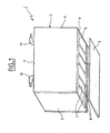
- Figure 1 shows the housing 1 of a one-piece nickel-metal battery hydrurable with capacity 120Ah and voltage 7.2V according to the present invention.
- the case 1 prismatic is composed of a polypropylene tank 2 and a means of closure 3 constituting a bottom.
- the tank 2 has two side walls 4, two walls longitudinal 5 and a transverse wall 6. It is divided into six cells 7 by partitions 8.
- Each cell 7 is intended to contain an accumulator element, that is to say an electrochemical beam formed by the alternative assembly of electrodes positive and negative separated from each other by a separator.
- the bottom 3 is intended to be heat sealed on tray 2 once the accumulator elements have been introduced in their respective cells.
- Flanges 9 are welded to the walls 5 to form a compartment for circulation for the heat transfer fluid.
- the thickness of the circulation compartment with the flange is about 2 to 4mm
- the transverse wall 6 carries pipes 10 for the inlet and outlet of the fluid.
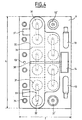
- the holes 11 intended to receive the terminals are arranged two by two one next to the other forming a band in the center of wall 6 as shown in the Figure 2.
- the orifices 12 which will receive the valves are aligned along the strip central on the side opposite the pipes 10.
- the cavity 13 is preferably located between two holes 12.
- FIG. 3 The schematic section along III-III is shown in Figure 3.
- a flange 9 is heat-sealed on each wall 5 delimiting a space 20, 20 'intended to receive a heat transfer fluid in circulation to cool or heat the battery according to the circumstances.
- a similar system has been described in the European patent application EP-0 596 778.
- air or a liquid can for example be used
- the coolant is for example a mixture of water and ethylene glycol.
- a passage 21 connects the compartments 20, 20 'with a pipe 10 common, for example for the entry of the fluid.
- Figure 4 shows a top view of the battery according to the invention equipped terminals and valves after introduction of the electrochemical harnesses in the alveoli and electrolyte filling.
- the current output terminals there, alternately positive 31 and negative 32 at the rate of one terminal of each polarity by alveolus, which are arranged two by two, one next to the other in the center of the wall 6.
- An positive terminal 31 of a first cell is electrically connected to a negative terminal 32 of a second neighboring cell using a flat connection 33.
- Each cell is provided with a safety valve 34 in the event of overpressure.
- the valve release pressure is usually between 1 bar and 3 bars relative, and most often of the order of 2 bars.
- the terminals 31, 32 are covered with a cover 35, with the exception of one terminal positive 31 'and a negative terminal 32' preferably located near the ends of the wall 6.
- the terminals 31 ', 32' do not carry a connection 33 and are intended to be electrically connected to an external circuit.
- the cover 35 is heat sealed so waterproof on wall 6. Heat sealing is carried out so that each couple of terminals 31, 32 connected by a connection 33 is surrounded by a closed continuous cord heat seal 36.
- side tabs 37 project from the cover 35 parallel to the wall 6.
- the wires running longitudinally the battery can be placed in the space being between these tabs and the wall 6 in order to be held in place.
- a box 39 containing for example the electronic components.
- the height of the box 39 must be such that, once installed in the housing 14, its elevation above the wall 6 does not exceed the height of the envelope volume of the equipped transverse wall.
- the monobloc battery shown has a length L of 250mm and a width l 120mm; its total height H is 200mm.
- the total height h of the envelope volume of the fitted transverse wall, including the cover, is 25mm.
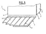
- FIG. 5 shows a variant of the invention according to which the bottom 3 of the housing 1 has six surfaces 40 corresponding to the six cells 7 of the battery.
- the surfaces 40 are delimited by flat zones 41 which will be heat-sealed on the walls of the tank 4, 5 and the corresponding partitions 8.
- the surfaces 40 have a shape rounded whose concavity is turned towards the outside of the battery. So the slight deformation (of the order of mm) induced by the internal overpressure remains contained in the one-piece battery envelope volume.
- the monobloc battery can be surrounded by a metal frame in order to strengthen the mechanical strength and facilitate gripping.
- the chassis is composed of two plates held by two tie rods, the plates being placed at each end of the battery in contact with the side walls.
- the plates have a thickness between 1 and 20mm, and preferably between 4 and 15mm, depending on the width of the electrochemical beam.
- the plates and tie rods are preferably made of metal for better mechanical strength, e.g. aluminum alloy, stainless steel, steel protected, a composite material.
- the plates have a concavity facing outwards of the battery and the side walls also have a concavity facing the exterior which follows the shape of the plates.
- Deformation induced by swelling electrochemical bundles is between 5 and 20% of the thickness of the plates, for example about 1mm for 9.5mm thick plates. So the deformation remains contained in the envelope volume of the monobloc battery.
Landscapes
- Chemical & Material Sciences (AREA)
- Chemical Kinetics & Catalysis (AREA)
- Electrochemistry (AREA)
- General Chemical & Material Sciences (AREA)
- Engineering & Computer Science (AREA)
- Manufacturing & Machinery (AREA)
- Secondary Cells (AREA)
- Sealing Battery Cases Or Jackets (AREA)
- Gas Exhaust Devices For Batteries (AREA)
Claims (15)
- Gasdichte Monoblockbatterie, die ein prismatisches Gehäuse (1) besitzt, aufweisend:ein aus einem einzigen Stückes Plastikmaterial gebildeter Behälter (2), der zwei laterale Wände (4), zwei longitudinale Wände (5), eine transversale Wand (6) und wenigstens eine vertikale Zwischenwand (8), die zu den longitudinale Wände (5) senkrecht ist und die den Behälter (2) in Zellen (7), die zur Aufnahme eines elektrochemischen Bündels bestimmt sind, aufteilt, aufweist,ein Verschlussmittel für den Behälter, das ein Stück (3) ist, das gasdicht am Behälter (2) und an den Zwischenwänden (8) an der gegenüberliegenden Seite zu der transversale Wand (6) befestigt ist,zwei Flansche (9), die gasdicht auf jeder der longitudinale Wände (5) befestigt sind, wobei sie mit der Wand (5) einen Bewegungsbereich (20) für ein flüssiges Kühlmittel definieren,zwei Leitungen (10), die auf der transversalen Wand (6) des Behälters (2) angeordnet sind und durch Übergänge (21), die in der transversalen Wand (6) eingefügt sind, in Verbindung stehen, wobei sie einen Eingang und einen Ausgang für die gemeinsame Flüssigkeit in den Bereichen (20) bilden,zwei Öffnungen (11) pro Zelle (7), die in das Innere des Gehäuses führen, die nebeneinander an der transversaler Wand (6} angebracht und in einem zentralen Band zusammengefasst sind, das zu den besagten longitudinalen Wänden (5) parallel ist, wobei sie zur Aufnahme von elektrischen Stromausgangsklemmen bestimmt sind,eine einmündende Öffnung (12) pro Zelle (7), die auf der transversalen Wand (6) gemäß einem lateralen Band parallel zu dem zentralem Band an der Seite gegenüber den Leitungen (10) angeordnet sind, die zur Aufnahme eines Sicherheitsventils für den Ausstoß von Gas im Falle eines Überdrucks bestimmt ist.
- Monoblockbatterie gemäß Anspruch 1, wobei die transversale Wand außerdem wenigstens einen nicht geöffneten Hohlraum (13) trägt, der zur Aufnahme eines Temperaturmessmittels bestimmt ist, wobei der Hohlraum zwischen den zwei Öffnung (12) für die Ventile angeordnet ist.
- Monoblockbatterie gemäß einem der Ansprüchel und 2, wobei die transversale Wand außerdem mindestens einen eine nicht geöffnete Behausung (14) trägt, die zwischen den Leitungen angeordnet ist.
- Monoblockbatterie gemäß einem der vorhergehenden Ansprüche, wobei alle Teile des Gehäuses aus Plastikmaterial sind.
- Monoblockbatterie gemäß einem der vorhergehenden Ansprüche, wobei die Größe des zentralen Bands in der Größenordnung der Hälfte der Breite der transversalen Wand ist.
- Monoblockbatterie gemäß einem der vorhergehenden Ansprüche, wobei die Größe der transversalen Wand mindestens gleich 70 mm und höchstens gleich 180 mm ist.
- Monoblockbatterie gemäß einem der vorhergehenden Ansprüche, wobei das durch die transversale Wand eingeschlossene Volumen eine Höhe von höchstens gleich 40 mm besitzt.
- Monoblockbatterie gemäß einem der vorhergehenden Ansprüche, bei der eine Haube (35), die gasdicht auf der transversalen Wand befestigt ist, die Klemmen (31 32) mit Ausnahme von zwei Klemmen gegensätzlicher Polarität (31', 32'), die zum Verbinden mit externen Anschlüssen bestimmt sind, überdeckt.
- Monoblockbatterie gemäß Anspruch 8, bei der die Haube gasdicht um jedes Paar von Klemmen gegensätzlicher Polarität, welche jeweils zwei unterschiedlichen und elektrisch verbundenen Zellen zugehörig sind, geschweißt ist.
- Monoblockbatterie gemäß einem der Ansprüche8 und 9, bei der die Haube Mittel zum Aufrechterhaltung einer Platzierung von longitudinalen Leitungen trägt, wobei die longitudinalen Leitungen durch laterale Laschen (37) gebildet sind, die von der Haube parallel zur transversaler Wand hervorstehen.
- Monoblockbatterie gemäß einem der Ansprüche8 bis 10, bei der die Haube Mittel trägt, um transversale Leitungen zu fuhren, die durch schräge Rinnen (38) gebildet sind, die an der Oberfläche der Haube ausgeführt sind.
- Monoblockbatterie gemäß einem der vorhergehenden Ansprüche, in der das Verschlussmittel ein Stück aus einem im allgemeiner Form planen Plastikmaterial ist, bei dem jeder Abschnitt der Oberfläche (40), der durch die Peripherie einer Zelle begrenzt ist, eine Konkavität darstellt, die zur Außenseite der Batterie gerichtet ist.
- Monoblockbatterie gemäß einem der vorhergehenden Ansprüche, die durch einen Rahmen gehalten wird, der aus zwei Platten gebildet ist, wobei die Platten durch Bänder verbunden sind, die in Kontakt zu den lateralen Wände angeordnet sind.
- Monoblockbatterie gemäß Anspruch 13, bei der die Platten eine Konkavität darstellen, die zur Außenseite der Batterie gerichtet ist.
- Monoblockbatterie gemäß Anspruch 14, bei der die lateralen Wände eine auf die Außenseite gerichtete Konkavität darstellen, welche die Form der Platten annehmen.
Applications Claiming Priority (4)
| Application Number | Priority Date | Filing Date | Title |
|---|---|---|---|
| FR9711434 | 1997-09-15 | ||
| FR9711434A FR2768557A1 (fr) | 1997-09-15 | 1997-09-15 | Batterie monobloc munie d'un dispositif de gestion thermique |
| FR9805538 | 1998-04-30 | ||
| FR9805538A FR2768558B1 (fr) | 1997-09-15 | 1998-04-30 | Batterie monobloc munie d'un dispositif de gestion thermique |
Publications (2)
| Publication Number | Publication Date |
|---|---|
| EP0902494A1 EP0902494A1 (de) | 1999-03-17 |
| EP0902494B1 true EP0902494B1 (de) | 2004-07-07 |
Family
ID=26233801
Family Applications (1)
| Application Number | Title | Priority Date | Filing Date |
|---|---|---|---|
| EP98402259A Expired - Lifetime EP0902494B1 (de) | 1997-09-15 | 1998-09-14 | Monoblock Batterie mit Thermischekontrollanordnung |
Country Status (4)
| Country | Link |
|---|---|
| EP (1) | EP0902494B1 (de) |
| JP (1) | JP4358327B2 (de) |
| DE (1) | DE69824922T2 (de) |
| FR (1) | FR2768558B1 (de) |
Families Citing this family (11)
| Publication number | Priority date | Publication date | Assignee | Title |
|---|---|---|---|---|
| JP5049436B2 (ja) * | 2001-09-28 | 2012-10-17 | パナソニック株式会社 | 組電池 |
| FR2908557B1 (fr) * | 2006-11-14 | 2009-02-06 | Vehicules Electr Societe Par A | Batterie electrique comprenant un systeme de conditionnement mecanique et thermique |
| KR101156527B1 (ko) | 2010-06-01 | 2012-06-21 | 에스비리모티브 주식회사 | 전지팩 |
| JP5793969B2 (ja) * | 2011-05-31 | 2015-10-14 | トヨタ自動車株式会社 | 積層電池 |
| DE202011052087U1 (de) * | 2011-11-24 | 2013-02-25 | Rehau Ag + Co. | Rahmen und System zum Halten und Temperieren einer Batteriezelle |
| FR3016083A1 (fr) | 2013-12-26 | 2015-07-03 | Commissariat Energie Atomique | Module de batterie electrochimique offrant une tenue aux environnements humides amelioree et procede de realisation d'au moins un tel module |
| FR3016086B1 (fr) * | 2013-12-26 | 2017-12-22 | Commissariat Energie Atomique | Batterie electrochimique a securite de fonctionnement amelioree en environnement humide |
| FR3050074B1 (fr) | 2016-04-07 | 2018-06-22 | Commissariat A L'energie Atomique Et Aux Energies Alternatives | Dispositif electrochimique, tel qu’une microbatterie, et son procede de realisation |
| FR3074362B1 (fr) * | 2017-11-24 | 2019-11-15 | Arkema France | Dispositif de refroidissement et/ou chauffage d'une batterie de vehicule automobile electrique ou hybride et circuit de refroidissement et/ou chauffage associe |
| CN113314781B (zh) * | 2020-01-07 | 2022-10-25 | 福建中维动力科技股份有限公司 | 一种冷却效果均匀的矿用汽车电池组冷却结构 |
| CN114110307A (zh) * | 2021-11-17 | 2022-03-01 | 广东电网有限责任公司广州供电局 | 一种柔直换流阀阀段框架结构 |
Family Cites Families (4)
| Publication number | Priority date | Publication date | Assignee | Title |
|---|---|---|---|---|
| DE9210384U1 (de) * | 1992-08-04 | 1992-09-24 | Varta Batterie Ag, 3000 Hannover | Mehrzellige Akkumulatorenbatterie mit Kühlung |
| FR2697677B1 (fr) * | 1992-11-02 | 1994-12-30 | Europ Accumulateurs | Batterie d'accumulateurs thermorégulée, notamment pour véhicule électrique. |
| US5460900A (en) * | 1994-08-08 | 1995-10-24 | Gnb Battery Technologies Inc. | Lead-acid battery having a fluid compartment for reducing convection-induced heat transfer |
| FR2742002B1 (fr) * | 1995-11-30 | 1998-02-20 | Peugeot | Batterie d'accumulateur electrique munie de moyens de refroidissement |
-
1998
- 1998-04-30 FR FR9805538A patent/FR2768558B1/fr not_active Expired - Fee Related
- 1998-09-14 JP JP26026198A patent/JP4358327B2/ja not_active Expired - Fee Related
- 1998-09-14 DE DE1998624922 patent/DE69824922T2/de not_active Expired - Lifetime
- 1998-09-14 EP EP98402259A patent/EP0902494B1/de not_active Expired - Lifetime
Also Published As
| Publication number | Publication date |
|---|---|
| FR2768558B1 (fr) | 2000-01-21 |
| EP0902494A1 (de) | 1999-03-17 |
| DE69824922D1 (de) | 2004-08-12 |
| FR2768558A1 (fr) | 1999-03-19 |
| JPH11144756A (ja) | 1999-05-28 |
| JP4358327B2 (ja) | 2009-11-04 |
| DE69824922T2 (de) | 2005-08-25 |
Similar Documents
| Publication | Publication Date | Title |
|---|---|---|
| FR2768557A1 (fr) | Batterie monobloc munie d'un dispositif de gestion thermique | |
| EP0964460B1 (de) | Monoblock Batterie mit Wärmtauschvorrichtung mittels Durchleiten einer Flüssigkeit | |
| EP0902494B1 (de) | Monoblock Batterie mit Thermischekontrollanordnung | |
| EP3516711B1 (de) | Tragbares batteriegerät mit passivem luftkühlsystem | |
| EP0596778B1 (de) | Einteilige Akkumulatorenbatterie mit Kühlungseinrichtung | |
| EP0933830A1 (de) | Verschlossene monoblock Batterie mit Kühlungsvorrichtung | |
| EP3499603B1 (de) | Querleiste, die als klemmenleiste für elektrochemischen metallionen-akku dient, und entsprechender akku | |
| WO2019197335A1 (fr) | Unite de batterie avec des moyens de regulation de la temperature integres au boitier | |
| EP3499602A1 (de) | System zur nachverfolgung von gasen in einem batteriepaket, entsprechender elektrochemischer metallionen-akku, der eine klemmenbildende querleiste zur integration einer sicherheitsentlüftung für das nachverfolgungssystem umfasst | |
| EP4005008B1 (de) | Batteriekühlmodul und vorrichtung sowie entsprechende batterie | |
| FR2737940A1 (fr) | Batterie d'elements accumulateurs electriques a haute temperature | |
| EP0913874A1 (de) | Verschlossener Akkumulator mit mehrschichtiger Ummantelung | |
| EP3499606A1 (de) | Mechanisches schnittstellenelement, das auch zur elektrischen isolierung zwischen zwei elektrochemischen metallionen-akkus dient, die auf ihrer längsachse in reihe geschaltet sind, und entsprechendes akku-modul | |
| WO2024062012A1 (fr) | Module electrique comprenant une pluralite de cellules de batteries immergees dans un liquide dielectrique | |
| EP3499608A1 (de) | Untereinheit, die einen hohldorn und einen teil einer hohlen querleiste umfasst, die als klemmenleiste für einen elektrochemischen metallionen-akku dient, und entsprechender akku | |
| FR2998715A1 (fr) | Batterie electrique modulaire, notamment pour vehicules automobiles, en particulier de type hybride ou electrique | |
| WO2021160948A1 (fr) | Dispositif de refroidissement d'un composant électrique et/ou électronique susceptible de dégager de la chaleur en fonctionnement | |
| WO2021116551A1 (fr) | Compartiment pour un equipement susceptible de degager de la chaleur | |
| FR3078828A1 (fr) | Batterie electrique pour vehicule | |
| FR2951029A1 (fr) | Module et unite de stockage d'energie electrique plat pour coffre a bagage de vehicule et procede de mise en place | |
| WO2021123538A1 (fr) | Compartiment pour un équipement susceptible de dégager de la chaleur | |
| FR2742002A1 (fr) | Batterie d'accumulateur electrique munie de moyens de refroidissement | |
| EP3915160B1 (de) | Vorrichtung eines energiespeichers für ein mobiles fahrzeug | |
| EP4420185A1 (de) | Batteriemodul mit zwischenstücken, zugehörige batterie und fahrzeug | |
| EP3707772B1 (de) | Kühlelement einer elektrischen speichervorrichtung für ein kraftfahrzeug |
Legal Events
| Date | Code | Title | Description |
|---|---|---|---|
| PUAI | Public reference made under article 153(3) epc to a published international application that has entered the european phase |
Free format text: ORIGINAL CODE: 0009012 |
|
| AK | Designated contracting states |
Kind code of ref document: A1 Designated state(s): DE FR GB |
|
| AX | Request for extension of the european patent |
Free format text: AL;LT;LV;MK;RO;SI |
|
| RAP3 | Party data changed (applicant data changed or rights of an application transferred) |
Owner name: ALCATEL |
|
| 17P | Request for examination filed |
Effective date: 19990917 |
|
| AKX | Designation fees paid |
Free format text: DE FR GB |
|
| GRAP | Despatch of communication of intention to grant a patent |
Free format text: ORIGINAL CODE: EPIDOSNIGR1 |
|
| GRAS | Grant fee paid |
Free format text: ORIGINAL CODE: EPIDOSNIGR3 |
|
| GRAA | (expected) grant |
Free format text: ORIGINAL CODE: 0009210 |
|
| AK | Designated contracting states |
Kind code of ref document: B1 Designated state(s): DE FR GB |
|
| REG | Reference to a national code |
Ref country code: GB Ref legal event code: FG4D Free format text: NOT ENGLISH |
|
| REF | Corresponds to: |
Ref document number: 69824922 Country of ref document: DE Date of ref document: 20040812 Kind code of ref document: P |
|
| GBT | Gb: translation of ep patent filed (gb section 77(6)(a)/1977) |
Effective date: 20040908 |
|
| RAP2 | Party data changed (patent owner data changed or rights of a patent transferred) |
Owner name: SAFT FINANCE S.AE.R.L. |
|
| PLBE | No opposition filed within time limit |
Free format text: ORIGINAL CODE: 0009261 |
|
| STAA | Information on the status of an ep patent application or granted ep patent |
Free format text: STATUS: NO OPPOSITION FILED WITHIN TIME LIMIT |
|
| 26N | No opposition filed |
Effective date: 20050408 |
|
| PGFP | Annual fee paid to national office [announced via postgrant information from national office to epo] |
Ref country code: GB Payment date: 20120828 Year of fee payment: 15 |
|
| PGFP | Annual fee paid to national office [announced via postgrant information from national office to epo] |
Ref country code: DE Payment date: 20120827 Year of fee payment: 15 |
|
| GBPC | Gb: european patent ceased through non-payment of renewal fee |
Effective date: 20130914 |
|
| REG | Reference to a national code |
Ref country code: DE Ref legal event code: R119 Ref document number: 69824922 Country of ref document: DE Effective date: 20140401 |
|
| PG25 | Lapsed in a contracting state [announced via postgrant information from national office to epo] |
Ref country code: GB Free format text: LAPSE BECAUSE OF NON-PAYMENT OF DUE FEES Effective date: 20130914 |
|
| PG25 | Lapsed in a contracting state [announced via postgrant information from national office to epo] |
Ref country code: DE Free format text: LAPSE BECAUSE OF NON-PAYMENT OF DUE FEES Effective date: 20140401 |
|
| REG | Reference to a national code |
Ref country code: FR Ref legal event code: PLFP Year of fee payment: 19 |
|
| PGFP | Annual fee paid to national office [announced via postgrant information from national office to epo] |
Ref country code: FR Payment date: 20160907 Year of fee payment: 19 |
|
| REG | Reference to a national code |
Ref country code: FR Ref legal event code: ST Effective date: 20180531 |
|
| PG25 | Lapsed in a contracting state [announced via postgrant information from national office to epo] |
Ref country code: FR Free format text: LAPSE BECAUSE OF NON-PAYMENT OF DUE FEES Effective date: 20171002 |