EP0902455B1 - Drehanoden-Röntgenröhre mit einem hydrodynamischen Gleitlager - Google Patents
Drehanoden-Röntgenröhre mit einem hydrodynamischen Gleitlager Download PDFInfo
- Publication number
- EP0902455B1 EP0902455B1 EP98202924A EP98202924A EP0902455B1 EP 0902455 B1 EP0902455 B1 EP 0902455B1 EP 98202924 A EP98202924 A EP 98202924A EP 98202924 A EP98202924 A EP 98202924A EP 0902455 B1 EP0902455 B1 EP 0902455B1
- Authority
- EP
- European Patent Office
- Prior art keywords
- bearing
- ray tube
- rotating anode
- intermediate pieces
- holder
- Prior art date
- Legal status (The legal status is an assumption and is not a legal conclusion. Google has not performed a legal analysis and makes no representation as to the accuracy of the status listed.)
- Expired - Lifetime
Links
- 125000006850 spacer group Chemical group 0.000 description 10
- 238000004519 manufacturing process Methods 0.000 description 6
- 230000001419 dependent effect Effects 0.000 description 2
- 239000000314 lubricant Substances 0.000 description 2
- 229910000807 Ga alloy Inorganic materials 0.000 description 1
- 238000010521 absorption reaction Methods 0.000 description 1
- 239000002826 coolant Substances 0.000 description 1
- 238000001816 cooling Methods 0.000 description 1
- 239000011521 glass Substances 0.000 description 1
- 230000017525 heat dissipation Effects 0.000 description 1
- 239000010687 lubricating oil Substances 0.000 description 1
- 238000000034 method Methods 0.000 description 1
Images
Classifications
-
- F—MECHANICAL ENGINEERING; LIGHTING; HEATING; WEAPONS; BLASTING
- F16—ENGINEERING ELEMENTS AND UNITS; GENERAL MEASURES FOR PRODUCING AND MAINTAINING EFFECTIVE FUNCTIONING OF MACHINES OR INSTALLATIONS; THERMAL INSULATION IN GENERAL
- F16C—SHAFTS; FLEXIBLE SHAFTS; ELEMENTS OR CRANKSHAFT MECHANISMS; ROTARY BODIES OTHER THAN GEARING ELEMENTS; BEARINGS
- F16C23/00—Bearings for exclusively rotary movement adjustable for aligning or positioning
- F16C23/02—Sliding-contact bearings
- F16C23/04—Sliding-contact bearings self-adjusting
-
- H—ELECTRICITY
- H01—ELECTRIC ELEMENTS
- H01J—ELECTRIC DISCHARGE TUBES OR DISCHARGE LAMPS
- H01J35/00—X-ray tubes
- H01J35/02—Details
- H01J35/04—Electrodes ; Mutual position thereof; Constructional adaptations therefor
- H01J35/08—Anodes; Anti cathodes
- H01J35/10—Rotary anodes; Arrangements for rotating anodes; Cooling rotary anodes
- H01J35/101—Arrangements for rotating anodes, e.g. supporting means, means for greasing, means for sealing the axle or means for shielding or protecting the driving
- H01J35/1017—Bearings for rotating anodes
- H01J35/104—Fluid bearings
-
- H—ELECTRICITY
- H01—ELECTRIC ELEMENTS
- H01J—ELECTRIC DISCHARGE TUBES OR DISCHARGE LAMPS
- H01J2235/00—X-ray tubes
- H01J2235/10—Drive means for anode (target) substrate
- H01J2235/1046—Bearings and bearing contact surfaces
- H01J2235/106—Dynamic pressure bearings, e.g. helical groove type
Definitions
- the invention relates to a rotating anode X-ray tube with one of the storage Rotating anode-serving slide bearing, which has an inner bearing segment and an outer one Bracket bearing segment includes, between the bracket and the inner bearing segment are spacers and with each other correspondingly shaped bearing surfaces on the inner bearing segment and in the Intermediate pieces for receiving radial and axial bearing forces are provided.
- the invention also relates to a rotary anode X-ray tube usable plain bearing.
- Such a rotating anode X-ray tube or such a plain bearing are from the DE-GM 87 05 478 known.
- the spacers are with their outer surfaces the tubular holder and the inner surface of the frustoconical Adjusted storage areas on the inner bearing segment.
- the load capacity of a plain bearing is largely dependent on the distance between the inside and outer bearing segment interacting bearing surfaces dependent.
- Such low and Constant distances over the storage area can only be achieved by an exact and achieve costly manufacturing.
- the known slide bearing has the advantage that only two (frustoconical) bearing surfaces on the inner bearing segment and in the Intermediate pieces must be processed with the required accuracy.
- those guided in the tubular holder must also Outer surfaces of the spacers exactly concentric with those provided conical bearing surfaces run, because otherwise the bearing surfaces tilt.
- the outer diameter of the spacers must be very precise be adapted to the inside diameter of the tubular holder, on the one hand the intermediate pieces are displaceable in the tubular holder and on the other hand, no leeway between the facing surfaces of the Intermediate pieces on the one hand and the tubular holder on the other hand remain.
- the object of the present invention is to use a rotating anode X-ray tube specify a plain bearing that can be manufactured with reduced manufacturing effort.
- a rotating anode X-ray tube of the type mentioned at the beginning solved this problem in that the mutually facing surfaces of the Intermediate pieces and the bracket are shaped so that the intermediate pieces can align within the bracket according to the bearing surfaces.
- On Slide bearing according to the invention is specified in claim 10.
- the shape of the mutually facing surfaces the bracket and the intermediate pieces achieved that the bearing surfaces in the Intermediate pieces corresponding to the bearing surfaces on the inner bearing segment can align, even if the in contact with the bracket coming outer surfaces of the intermediate pieces are not exactly concentric to the inside provided storage areas.
- the maximum required Tilt angle depends on the accuracy of manufacture; however, he can also use low manufacturing costs can be kept small, e.g. less than 1 °.
- the surfaces mentioned could both, as in the case of a spherical plain bearing be shaped like a spherical cap. There is less manufacturing effort but if the surfaces mentioned designed according to claims 2 and 3 are.
- the bearing surfaces must be shaped so that they are radial on the one hand and on the other can absorb axial bearing forces, being that of the two bearings Axial bearing forces to be absorbed are opposed to each other.
- the normal ones on the rotationally symmetrical bearing surfaces are therefore allowed - at least in one certain area - neither parallel nor perpendicular to the axis of rotation.
- a shape of the bearing surfaces that can be produced with relatively little effort is shown in Claim 4 specified.
- Claim 5 describes an embodiment, the assembly of the plain bearing facilitated.
- the adjustment of the two parts and so that the setting of the bearing play can be carried out by the one part is more or less screwed into the other. That for the function of the Plain bearing decisive bearing play is not here - as with rotating anode X-ray tubes with separate bearing surfaces for the axial and radial bearing forces - Given by a highly precise production, but by a simple one Setting process.
- the friction between the spacers and the bracket is sufficient to prevent the intermediate pieces from rotating relative to the bracket to prevent rotating plain bearings. If necessary, it is possible to Possibility of such twisting by the specified in claim 7 Prevent design entirely.
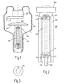
- Fig. 1 shows schematically a rotating anode X-ray tube, the vacuum piston - e.g. made of glass - is labeled 101.
- a cathode is on the vacuum piston 101 102 and a rotating anode 103 attached.
- the rotating anode includes an anode disk 104, which is connected to a holder 105.
- a rotor 106 is on the bracket attached to the outside with a stator, not shown Tube piston 101 cooperates to drive the anode disk 104.
- the anode disk 104 is mounted in a slide bearing, which is made up of an outer (in this case rotatable) bearing segment and an inner, (fixed) bearing segment.
- the plain bearing is in one in Fig. 2 shown larger scale than in Fig. 1.
- a similar bearing surface 111 is provided in the area of the axis 109 however tapered downwards, with the axis 109 correspondingly reduced diameter continues downwards.
- the bearing surfaces 110 and 111 form together with the also frustoconical inner surfaces of two spacers 112 and 113 each a spiral groove bearing that absorb axial and radial bearing forces at the same time can.
- the outer surfaces of the intermediate pieces 112, 113 preferably have the shape a spherical cap.
- the outer surface of the adapter 112 is supported on one truncated cone-shaped inner surface 114 symmetrical to the axis of rotation Bracket part 105 from. Analogously, the outer surface of the lower one is supported Intermediate piece 113 on the conical inner surface 115 of another, likewise from the axis of rotation symmetrical mounting part 116, which over a Thread adjustable in the axial direction is connected to the holding part 105.
- the two bracket parts 105 and 116 together form a bracket 108, the supports the intermediate pieces 112 and 113 in the radial and axial directions.
- a low-level liquid lubricant Vapor pressure for example a gallium alloy.
- the Bracket 116 When reassembling the plain bearing, the Bracket 116 inserted the adapter 112 into the bracket, after which the Axis 109 is inserted into the holder and the intermediate piece 113 on the lower storage area is pushed on. Thereafter, the bracket member 116 in the Bracket 105 is screwed in, the outer surfaces of the Align spacers 112 and 113 so that they are inside Bearing surfaces are pressed over the entire surface on the bearing surfaces 110 and 111. After that the holding part 116 is released in a defined manner in order to achieve the desired Adjust bearing play.
- a cooling bore extending in the axial direction can be located in the interior of the axis 9 be provided, through which the heat generated by a suitable cooling medium the bracket, the spacers and the lubricant on the axle 109 arrives, can be dissipated.
- the anode disk 104 rotates, the Intermediate pieces 112, 113 synchronously with this. Your interface with the Bracket parts 105 and 116 are small, but generally sufficient to take the intermediate pieces 113 with them.
- Rotation between the intermediate pieces 112, 113 and the bracket parts 105, 116 can be avoided by the fact that - as in FIG. 5 for the holding part 116 shown in a plan view - the holding part with a radially arranged, projecting rib 121 (or a pin) is provided, which in a no closer shown groove can engage in the intermediate piece.
- This groove should be deeper than the rib 121 so that only the convex outer surface of the intermediate piece is exposed can support the conical inner surfaces 114 and 115.
- the Grooves should be wider than the ribs so that the spacers opposite the Inner surfaces can be tilted.
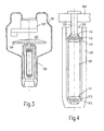
- FIGS. 3 and 4 An embodiment is shown in which the outer bearing segment of the plain bearing with the tubular piston and the inner bearing segment is connected to the anode disk 104.
- the rotor 106 is connected to a shaft 129.
- the anode disk is carried by shaft 129 which widens in the shape of a truncated cone in the area of a bearing surface 110 and into a section with a larger diameter, at the end of which is frustoconical bearing surface 111 is located.
- the Bearing surfaces 110, 111 in turn form with the correspondingly shaped ones Bearing surfaces in the intermediate pieces 112, 113 plain bearings for receiving radial and axial bearing forces.
- the bracket fixed when the anode disk rotates comprises a part 125 which is open towards the anode and is connected to the tube bulb, whose inner surfaces have a truncated cone at the lower end Have area 115 and one therein by means of an external thread in the axial Adjustable bracket portion 126, the frustoconical down directed surfaces 114 fix the upper intermediate piece 112. A heat dissipation due to a bore running in the axial direction is not easy possible.
- annular intermediate pieces at the upper end of the plain bearing according to Fig. 2 and 4 can also be formed cap-shaped at the lower end of the sliding bearing be and thus complete the upper or lower bearing towards the outside, so that no lubricant can escape there.
- the inner surfaces of the bracket have a conical and the outer surfaces of the intermediate pieces that come into contact with them convex, rotationally symmetrical shape.
- the areas mentioned can also be different be shaped, e.g. the shape of a spherical cap, or the inner surfaces can be concave and the outer surfaces conical.
- the spacers are opposite the bracket can be tilted.
Landscapes
- Engineering & Computer Science (AREA)
- General Engineering & Computer Science (AREA)
- Mechanical Engineering (AREA)
- Sliding-Contact Bearings (AREA)
- Support Of The Bearing (AREA)
Applications Claiming Priority (2)
| Application Number | Priority Date | Filing Date | Title |
|---|---|---|---|
| DE19739908A DE19739908A1 (de) | 1997-09-11 | 1997-09-11 | Drehanoden-Röntgenröhre mit einem hydrodynamischen Gleitlager |
| DE19739908 | 1997-09-11 |
Publications (3)
| Publication Number | Publication Date |
|---|---|
| EP0902455A2 EP0902455A2 (de) | 1999-03-17 |
| EP0902455A3 EP0902455A3 (de) | 2002-01-23 |
| EP0902455B1 true EP0902455B1 (de) | 2004-12-01 |
Family
ID=7841994
Family Applications (1)
| Application Number | Title | Priority Date | Filing Date |
|---|---|---|---|
| EP98202924A Expired - Lifetime EP0902455B1 (de) | 1997-09-11 | 1998-09-02 | Drehanoden-Röntgenröhre mit einem hydrodynamischen Gleitlager |
Country Status (4)
| Country | Link |
|---|---|
| US (1) | US6275567B1 (enExample) |
| EP (1) | EP0902455B1 (enExample) |
| JP (1) | JPH11149892A (enExample) |
| DE (2) | DE19739908A1 (enExample) |
Families Citing this family (3)
| Publication number | Priority date | Publication date | Assignee | Title |
|---|---|---|---|---|
| DE19931296A1 (de) * | 1999-07-07 | 2001-01-11 | Philips Corp Intellectual Pty | Drehanoden-Röntgenröhre mit axialer Lagerung |
| CN102822543B (zh) | 2010-03-31 | 2015-07-22 | 皇家飞利浦电子股份有限公司 | 用于x射线管的旋转阳极的支承系统 |
| US9972472B2 (en) * | 2014-11-10 | 2018-05-15 | General Electric Company | Welded spiral groove bearing assembly |
Family Cites Families (6)
| Publication number | Priority date | Publication date | Assignee | Title |
|---|---|---|---|---|
| NL6617168A (enExample) * | 1966-12-07 | 1968-06-10 | ||
| NL6706569A (enExample) * | 1967-05-11 | 1968-11-12 | ||
| NL7713634A (nl) * | 1977-12-09 | 1979-06-12 | Philips Nv | Roentgenbuis met draaianode. |
| NL8601414A (nl) * | 1986-06-02 | 1988-01-04 | Philips Nv | Roentgenbuis met een draaianode. |
| DE8705478U1 (de) | 1987-04-13 | 1988-08-11 | Siemens AG, 1000 Berlin und 8000 München | Röntgenröhre mit einer in einem Vakuumgehäuse untergebrachten Drehanode |
| US5173797A (en) * | 1990-05-08 | 1992-12-22 | Xerox Corporation | Rotating mirror optical scanner with grooved grease bearings |
-
1997
- 1997-09-11 DE DE19739908A patent/DE19739908A1/de not_active Withdrawn
-
1998
- 1998-09-02 DE DE59812319T patent/DE59812319D1/de not_active Expired - Fee Related
- 1998-09-02 EP EP98202924A patent/EP0902455B1/de not_active Expired - Lifetime
- 1998-09-09 JP JP10255430A patent/JPH11149892A/ja active Pending
- 1998-09-10 US US09/150,555 patent/US6275567B1/en not_active Expired - Fee Related
Also Published As
| Publication number | Publication date |
|---|---|
| EP0902455A2 (de) | 1999-03-17 |
| EP0902455A3 (de) | 2002-01-23 |
| US6275567B1 (en) | 2001-08-14 |
| DE19739908A1 (de) | 1999-03-18 |
| JPH11149892A (ja) | 1999-06-02 |
| DE59812319D1 (de) | 2005-01-05 |
Similar Documents
| Publication | Publication Date | Title |
|---|---|---|
| DE69623263T2 (de) | Schnellspannachse für ein fahrrad | |
| DE3206739C2 (enExample) | ||
| DE102004045629A1 (de) | Fluiddynamisches Lagersystem | |
| DE8808352U1 (de) | Druckwalze | |
| EP0435022A1 (de) | Lenkrolleneinheit | |
| DE3900730A1 (de) | Drehanoden-roentgenroehre mit wenigstens zwei spiralrillenlagern | |
| EP0902455B1 (de) | Drehanoden-Röntgenröhre mit einem hydrodynamischen Gleitlager | |
| EP3807012B1 (de) | Zentrifuge | |
| EP0895273B1 (de) | Drehanoden-Röntgenröhre mit einem Gleitlager | |
| EP0724283B1 (de) | Drehanoden-Röntgenröhre mit einem Gleitlager | |
| DE19734841A1 (de) | Mit einem aushängbaren Türscharnier baulich vereinigter Türfeststeller | |
| EP0664408B1 (de) | Kugelgelenk | |
| EP4076114B1 (de) | Mahlwerk, mahlscheibe für ein mahlwerk, und kaffeemaschine mit einem solchen mahlwerk | |
| EP1268986A1 (de) | Ventildrehvorrichtung | |
| DE69932241T2 (de) | Drehlager | |
| EP0753683A2 (de) | Scheibenbremse | |
| EP0938182A2 (de) | Lageranordnung | |
| EP1988311A2 (de) | Lagereinheit und damit ausgestattete Lineareinheit | |
| DE2917816C2 (de) | Lager für ein Periskop | |
| DE2745905C3 (de) | Vollbelag-Scheibenbremse für Fahrzeuge, insbesondere für Schlepper | |
| DE3206550C1 (de) | Zeichenkopf fuer Zeichenmaschinen | |
| DE2203919C3 (de) | Lenkrolle mit einer Lenkarretierungseinrichtung | |
| DE2459083C2 (de) | Axialkolbenmaschine | |
| DE102009039063B4 (de) | Dynamische Pumpdichtung für ein fluiddynamisches Lagersystem | |
| EP1527910B1 (de) | Anhängekupplung |
Legal Events
| Date | Code | Title | Description |
|---|---|---|---|
| PUAI | Public reference made under article 153(3) epc to a published international application that has entered the european phase |
Free format text: ORIGINAL CODE: 0009012 |
|
| AK | Designated contracting states |
Kind code of ref document: A2 Designated state(s): AT BE CH CY DE DK ES FI FR GB GR IE IT LI LU MC NL PT SE Kind code of ref document: A2 Designated state(s): DE FR GB NL |
|
| AX | Request for extension of the european patent |
Free format text: AL;LT;LV;MK;RO;SI |
|
| RAP3 | Party data changed (applicant data changed or rights of an application transferred) |
Owner name: KONINKLIJKE PHILIPS ELECTRONICS N.V. Owner name: PHILIPS CORPORATE INTELLECTUAL PROPERTY GMBH |
|
| PUAL | Search report despatched |
Free format text: ORIGINAL CODE: 0009013 |
|
| AK | Designated contracting states |
Kind code of ref document: A3 Designated state(s): AT BE CH CY DE DK ES FI FR GB GR IE IT LI LU MC NL PT SE |
|
| AX | Request for extension of the european patent |
Free format text: AL;LT;LV;MK;RO;SI |
|
| RIC1 | Information provided on ipc code assigned before grant |
Free format text: 7H 01J 35/10 A, 7F 16C 17/10 B, 7F 16C 23/04 B, 7F 16C 27/02 B, 7F 16C 33/10 B |
|
| 17P | Request for examination filed |
Effective date: 20020723 |
|
| RAP1 | Party data changed (applicant data changed or rights of an application transferred) |
Owner name: KONINKLIJKE PHILIPS ELECTRONICS N.V. Owner name: PHILIPS CORPORATE INTELLECTUAL PROPERTY GMBH |
|
| AKX | Designation fees paid |
Free format text: DE FR GB NL |
|
| RAP1 | Party data changed (applicant data changed or rights of an application transferred) |
Owner name: KONINKLIJKE PHILIPS ELECTRONICS N.V. Owner name: PHILIPS INTELLECTUAL PROPERTY & STANDARDS GMBH |
|
| GRAP | Despatch of communication of intention to grant a patent |
Free format text: ORIGINAL CODE: EPIDOSNIGR1 |
|
| GRAS | Grant fee paid |
Free format text: ORIGINAL CODE: EPIDOSNIGR3 |
|
| GRAA | (expected) grant |
Free format text: ORIGINAL CODE: 0009210 |
|
| AK | Designated contracting states |
Kind code of ref document: B1 Designated state(s): DE FR GB NL |
|
| PG25 | Lapsed in a contracting state [announced via postgrant information from national office to epo] |
Ref country code: NL Free format text: LAPSE BECAUSE OF FAILURE TO SUBMIT A TRANSLATION OF THE DESCRIPTION OR TO PAY THE FEE WITHIN THE PRESCRIBED TIME-LIMIT Effective date: 20041201 Ref country code: GB Free format text: LAPSE BECAUSE OF FAILURE TO SUBMIT A TRANSLATION OF THE DESCRIPTION OR TO PAY THE FEE WITHIN THE PRESCRIBED TIME-LIMIT Effective date: 20041201 |
|
| REG | Reference to a national code |
Ref country code: GB Ref legal event code: FG4D Free format text: NOT ENGLISH |
|
| REG | Reference to a national code |
Ref country code: IE Ref legal event code: FG4D Free format text: GERMAN |
|
| REF | Corresponds to: |
Ref document number: 59812319 Country of ref document: DE Date of ref document: 20050105 Kind code of ref document: P |
|
| NLV1 | Nl: lapsed or annulled due to failure to fulfill the requirements of art. 29p and 29m of the patents act | ||
| GBV | Gb: ep patent (uk) treated as always having been void in accordance with gb section 77(7)/1977 [no translation filed] |
Effective date: 20041201 |
|
| PLBE | No opposition filed within time limit |
Free format text: ORIGINAL CODE: 0009261 |
|
| STAA | Information on the status of an ep patent application or granted ep patent |
Free format text: STATUS: NO OPPOSITION FILED WITHIN TIME LIMIT |
|
| ET | Fr: translation filed | ||
| 26N | No opposition filed |
Effective date: 20050902 |
|
| PGFP | Annual fee paid to national office [announced via postgrant information from national office to epo] |
Ref country code: DE Payment date: 20071119 Year of fee payment: 10 |
|
| PGFP | Annual fee paid to national office [announced via postgrant information from national office to epo] |
Ref country code: FR Payment date: 20070926 Year of fee payment: 10 |
|
| REG | Reference to a national code |
Ref country code: FR Ref legal event code: ST Effective date: 20090529 |
|
| PG25 | Lapsed in a contracting state [announced via postgrant information from national office to epo] |
Ref country code: DE Free format text: LAPSE BECAUSE OF NON-PAYMENT OF DUE FEES Effective date: 20090401 |
|
| PG25 | Lapsed in a contracting state [announced via postgrant information from national office to epo] |
Ref country code: FR Free format text: LAPSE BECAUSE OF NON-PAYMENT OF DUE FEES Effective date: 20080930 |