EP0902393B1 - Bildverarbeitungsverfahren und thermischer Übertragungsdrucker - Google Patents
Bildverarbeitungsverfahren und thermischer Übertragungsdrucker Download PDFInfo
- Publication number
- EP0902393B1 EP0902393B1 EP98306515A EP98306515A EP0902393B1 EP 0902393 B1 EP0902393 B1 EP 0902393B1 EP 98306515 A EP98306515 A EP 98306515A EP 98306515 A EP98306515 A EP 98306515A EP 0902393 B1 EP0902393 B1 EP 0902393B1
- Authority
- EP
- European Patent Office
- Prior art keywords
- image
- pixel
- value
- contour
- original image
- Prior art date
- Legal status (The legal status is an assumption and is not a legal conclusion. Google has not performed a legal analysis and makes no representation as to the accuracy of the status listed.)
- Expired - Lifetime
Links
Images


Classifications
-
- G—PHYSICS
- G06—COMPUTING OR CALCULATING; COUNTING
- G06T—IMAGE DATA PROCESSING OR GENERATION, IN GENERAL
- G06T5/00—Image enhancement or restoration
- G06T5/73—Deblurring; Sharpening
-
- G—PHYSICS
- G06—COMPUTING OR CALCULATING; COUNTING
- G06T—IMAGE DATA PROCESSING OR GENERATION, IN GENERAL
- G06T7/00—Image analysis
- G06T7/10—Segmentation; Edge detection
- G06T7/13—Edge detection
-
- G—PHYSICS
- G06—COMPUTING OR CALCULATING; COUNTING
- G06T—IMAGE DATA PROCESSING OR GENERATION, IN GENERAL
- G06T2207/00—Indexing scheme for image analysis or image enhancement
- G06T2207/10—Image acquisition modality
- G06T2207/10004—Still image; Photographic image
- G06T2207/10008—Still image; Photographic image from scanner, fax or copier
-
- G—PHYSICS
- G06—COMPUTING OR CALCULATING; COUNTING
- G06T—IMAGE DATA PROCESSING OR GENERATION, IN GENERAL
- G06T2207/00—Indexing scheme for image analysis or image enhancement
- G06T2207/20—Special algorithmic details
- G06T2207/20172—Image enhancement details
- G06T2207/20192—Edge enhancement; Edge preservation
-
- G—PHYSICS
- G06—COMPUTING OR CALCULATING; COUNTING
- G06T—IMAGE DATA PROCESSING OR GENERATION, IN GENERAL
- G06T2207/00—Indexing scheme for image analysis or image enhancement
- G06T2207/30—Subject of image; Context of image processing
- G06T2207/30176—Document
Definitions
- the present invention relates to a method for enhancing a secondary differential value image, an image contour emphasizing process method based on the reconstructing process method, and a thermal transfer printer for performing recording based on the contour emphasizing process method and, more particularly, to a reconstructing process method, for a secondary differential value image, which corrects blurring at a contour portion of an original image to perform recording, an image contour emphasizing process method based on the reconstructing process method, and a thermal transfer printer for performing recording based on the contour emphasizing process method.
- thermal transfer printer which comprises an image scanner serving as a means for reading information of an original such as an image or a document and has an easy copy function for performing a conversion process for the information loaded by the image scanner as recording data and causing a recording mechanism having a recording head to perform recording based on the recording data has been proposed.
- Such a conventional thermal transfer printer comprising an image performs a conversion process image information of an original as recording data, in order to perform recording such that the contour portion of the original image, i.e., an edge is emphasized (made sharp), a contour emphasizing process for an image is performed.
- FIG. 27A shows a function f(x) representing a variable density section of an edge of an original image
- FIG. 27B shows the first derivative df/dx of the function f(x)
- FIG. 27C shows the second derivative d 2 f/dx 2 of the function f(x).
- a contour emphasizing process represented by the process of subtracting the function in FIG. 27C from the function in FIG. 27A, i.e., f(x) - d 2 f/dx 2 is performed.
- the second derivative d 2 f/dx 2 has positive and negative values before and after the slope of the edge. For this reason, a change in density of the edge can be enlarged by the function f-d 2 f/dx 2 in FIG. 27D.
- Such an effect is similar to the Mach effect observed by a sense of a person.
- a person When several belt-like patterns having different brightnesses are seen, a person generally feels as if the boundary between belts in which density changes in a step-like manner is temporarily darkened and then brightened again.
- an edge emphasizing process output valve is overshot or undershot. For this reason, if an original image is a blurred image, in order to emphasize the contour portion of the original image to obtain a sharp contour, the contour unnaturally appears in the actual recorded image, or the peripheral portion of the contour portion is blurred.
- a method for enhancing a second derivative value image characterised in that a first derivative value and a second derivative value of each pixel in an original image are calculated, the original image is scanned in horizontal and vertical directions to detect a contour line on the basis of the signs of the first derivative value and the second derivative value, a region to be emphasized is defined along the contour line in a normal direction with respect to a tangent to each pixel on the contour line, and for each pixel in the region to be emphasized and a second derivative value, located at a position which is shifted by a predetermined width in a normal direction with respect to a tangent to each pixel on the contour line, is substituted as the second derivative value.
- pixels of the contour lines and pixels between the contour lines are excluded from pixels subjected to the enhancement method.
- a corresponding output value of a second derivative value image is multiplied by an emphasizing coefficient, and the resultant value is added to or subtracted from the pixel value of the original image to emphasize the contour in the original image.
- a thermal transfer printer comprising: an image scanner for reading information of an original image; a controller for performing a conversion process for the information of the original image read by said image scanner as recording data; and a recording head for performing recordin on the basis of the recording data, and said controller being adapted to calculate a first derivative value and a second derivative value of each pixel in an original image, the original image being scanned in horizontal and vertical directions to detect a contour line on the basis of the signs of the first derivative value and the second derivative value, to define a region to be emphasized along the contour line in a normal direction with respect to a tangent to each pixel on the contour line, and for each pixel in the region to be emphasized to substitute a second derivative value located at a position which is shifted by a predetermined width in a normal direction with respect to a tangent to each pixel on the contour line, as the second derivative value to enhance the second derivative value image, to multiply for each pixel of the original image
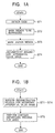
- a method for enhancing a secondary differential value image according to the present invention is performed in the following order. That is, a contour line is detected from an original image, i.e., edge detection is performed (step ST1); a region to be emphasized is marked to determine a region for thickening the detected edge by the width of several pixels (step ST2); a region in which an interval between contour lines is small is detected to be marked, i.e., an uneven region is marked (step ST3); and a secondary differential value image is reconstructed to emphasize pixels of a contour portion (step ST4).
- An image contour emphasizing process method is designed such that, as shown in the flow chart in FIG. 1B, each pixel is subjected to an emphasizing process (step ST5) on the basis of an output value of a secondary differential value image obtained by the reconstructing process.
- step ST1 The edge detection in step ST1 will be described below with reference to FIGS. 2 to 4.
- FIG. 2 shows an example of a coordinate map of an input image.
- an image of m (lateral) x n (longitudinal) is expressed.
- the horizontal direction of the original image is set to be an i-direction
- the vertical direction is set to be a j-direction.
- a step edge is detected from the first and second derivative values according to the following procedure.
- first derivative output values dx(i,j) and dy(i,j) in the x-direction and the y-direction are calculated from Equations (1) and (2).
- Equation (3) a second derivative output value L(i,j) is calculated from Equation (3).
- the second derivative output value L(i,j) is independently scanned in the x-direction and the y-direction to form an edge map in the x-direction and an edge map in the y-direction.
- the second derivative output value L(i,j) is scanned to obtain a pair of adjacent pixels which are changed from a negative state to a positive state or from the positive state to the negative state (0 is included in the negative state) and have second derivative values (absolute values) larger than a threshold value.
- step edge has a shape shown in FIG. 3.
- Labels are sequentially added to the detected pair of edges from the left to the right in the x-direction.
- the upper and lower sides are defined as the left and right sides in advance, respectively, and -labels are sequentially added to the detected pair of edges from the left to the right.
- the addition of the labels L and R is performed to determine an emphasizing direction in the emphasizing process. More specifically, since a pair of edges (two pixels) are detected, an emphasized region is added in the forward and backward directions of a gradient direction (to be described later) obtained from the center of the two pixels, and, on the basis of this direction, the direction of parallel shift of a second derivative used in the emphasizing process is determined. For this reason, the labels L and R must be determined to discriminate the forward direction from the backward direction with respect to the gradient direction.
- the step width which is a parameter of Equations (1), (2), and (3) is in proportion to the degree of definition of the detected edge. For this reason, when the definite edge is detected, the step width is decreased. When a rough edge is detected, the step width is gradually increased. In this embodiment, since the definite portion is emphasized by a contour emphasizing process, the step width is appropriately set to be about 1 to 2.
- step ST2 in FIG. 1A Marking of a region to be emphasized in step ST2 in FIG. 1A will be described below.
- a reconstructing process for a secondary differential value image is to emphasize a region in which the step edge detected in step ST1 is thickened by the width of several pixels. For this reason, the marking of the region to be emphasized is performed by adding pixels to be emphasized to an additional direction after the additional direction of the region to be emphasized is determined.
- a normal direction this is called a "gradient direction" with respect to the tangent of the step edge is calculated, and a region to be emphasized is determined to the forward direction and backward direction of the gradient direction.
- a direction in which the region to be emphasized is added to the pixels of the pair of edges is determined by the gradient direction and the combination labels.
- the determination of the additional direction of the region to be emphasized is roughly divided into the following four steps. That is, as the first step, a combination label is added to an interest pixel; as the second step, the gradient direction of a step edge is calculated; as the third step, a combination label is added to the interest pixel in an inclined direction; and as the fourth step, an additional direction is determined.
- a combination label is added to the interest pixel by the following manner. That is, combination labels shown in Table 1 are added by the combination of the labels from the labels L, R, and ZERO in the x-direction and the y-direction marked on the edges by the edge detection in step ST1.
- Combination of Labels x-direction y-direction
- the gradient direction means a direction in which luminance is changed from low to high at a certain edge, and represents a normal direction with respect to a tangent at an interest pixel on an edge (contour line).
- the gradient direction is calculated by using primary differential values of interest pixels in the x-direction and the y-direction.
- an edge label x e in the horizontal direction an edge label y e in the vertical direction
- a first derivative value dx e in the x-direction (horizontal direction) a first derivative value y e in the y-direction (vertical direction)
- , b
- a
- , b
- Conditions set to include gradient directions in the respective conditions are as follows.
- 16 or more directions e.g., 32 directions can also be set.
- the differences between results appearing in images cannot be visually recognized.
- Addition of the combination label in the inclined direction of the interest pixel is performed as follows. That is, as shown in FIG. 9, if no label exists in a pixel, with reference to a pixel label in an inclined direction indicated by a dotted line, a label is added to the pixel having a combination between interest pixels indicated by solid lines.
- one direction of 16 directions is selected by combination labels of respective edge pixels and a gradient direction.
- a pixel width (additional pixel width) which is twice a step width given when a first derivative value and a second derivative value are calculated is added as a region to be emphasized. Methods of adding pixels change depending on the additional directions.
- pixels corresponding to the width of added pixels are added from an interest pixel in an additional direction to be marked.
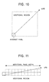
- a region in which an additional direction from an interest pixel serves as a diagonal direction of a square, and a square region which has one side having a length corresponding to the width of the added pixels is marked.
- a square region shown in FIG. 10 is an additional region of a pixel to be emphasized.
- a rectangular region which has one side having a length corresponding to the width of the added pixels along the additional direction and has one side having a length corresponding to the width of two pixels is marked.
- a rectangular region shown in FIG. 11 is an additional region of a pixel to be emphasized.
- step ST2 marking of a region to be emphasized in step ST2 is completed.
- the uneven region is called a region in which step edges are adjacent to each other by a narrow interval between contour lines to form an uneven portion.
- This region is shown in FIG. 12.
- FIG. 12A shows a sectional shape of a certain step edge
- FIG. 12B shows an additional direction of an emphasized pixel.
- reference symbols A to D denote pairs of edges, respectively; A, the left pixel of one pair of edges; B, the right pixel of the same pair of edges; C, the left pixel of an adjacent pair of edges; and D, the right pixel of the same pair of edges.
- FIG. 12C shows an uneven region and a target region. In FIG. 12C, a range surrounded by a bold line indicates the uneven region.
- FIG. 13 is a view for explaining an output value when an emphasizing process is performed by a secondary differential value image reconstructed with respect to a projection edge.
- the emphasizing process is performed by a reconstructed secondary differential value image, an output value between the projection edges sharply increases or decreases.
- an interval between adjacent step edges is smaller than a length four times the step width (the width of pixels added to each edge is smaller than 2 x step width), and two step edges form an uneven portion.
- a region sandwiched by the two edges is defined as an uneven region.
- a contour portion including the uneven region is partially excluded from pixels subjected to a reconstructing process for a secondary differential value image.
- two adjacent edges having a pixel interval larger than the width of two pixels and smaller than 4 x step width in an edge map in an x-direction and a y-direction are detected.
- the above combination labels are marked.
- a pair of edges having a pixel interval which is 2 to 4 x step width and constituting a combination in lateral, longitudinal, and diagonal directions in FIG. 14 are detected.
- a pixel sandwiched between these edges is marked as an uneven region.
- the pixel is excluded from a pixel subjected to a reconstructing process for a secondary differential value image, i,e., the pixel has the original second derivative value of the corresponding pixel.
- FIG. 15 additional regions to be emphasized on the left of an L-ZERO label and the right of an R-ZERO label are subjected to a reconstructing process for a secondary differential value image.
- a secondary differential value image is not reconstructed as an uneven edge region, and a second derivative value at the pixel position is left.
- a waveform near the uneven region obtained by the process is shown in FIG. 16.
- FIG. 16 is compared with FIG. 13, it is understood that overshooting and undershooting are prevented to obtain a stable output.
- a secondary differential value image is reconstructed.
- a contour emphasizing process is performed by directly using a second derivative value in the following step ST5 as in a prior art, as shown in FIG. 17A, unnatural overshooting or ' undershooting occurs. This is because the peak of the second derivative value of a blurred contour portion (edge) in an image becomes far away from the edge to both the sides as the degree of blurring increases.
- a second derivative value located at peaks on both the sides of the edge i.e., a position where a second derivative value parallelly shifted in a direction far away from the center of the edge by a predetermined width is substituted for each pixel marked as a region to be emphasized to reconstruct the secondary differential value image.
- FIG. 17B shows output waveforms obtained when the contour emphasizing process in the following process step ST5 is performed by using a second derivative image obtained by reconstruction for a secondary differential value image of this embodiment.
- an input image is represented by I(i,j)
- a secondary differential value image of an image obtained with a certain step width is represented by L(i,j).
- an input image is represented by I(i,j)
- a secondary differential value image obtained by causing the processes in the step ST1 to the step ST4 to reconstruct the secondary differential value image obtained with a certain step width is represented by S(i,j)
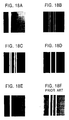
- FIG. 18A shows a blurred image used as an input image. As is apparent from FIG. 18A, the contours of two white and black lines are blurred.
- FIG. 18B shows an output image obtained such that edge detection (step ST1) is performed by using the blurred image in FIG. 18A as an input image.
- the left side of a pair of edges is output in red, and the right side is output in yellow.
- FIG. 18C shows an output image obtained such that marking (step ST2) for each region to be emphasized is performed by using the edge-detected image in FIG. 18B as an input.
- a red portion indicates a pixel which is additionally marked in the left direction of each edge pixel, and a yellow portion indicates a pixel which is additionally marked in the right direction.
- FIG. 18D shows an output image obtained such that an uneven region is marked (step ST3) such that a mark image of the region to be emphasized in FIG. 18C is used as an input.
- a green portion corresponds to an uneven region.
- FIG. 18E shows an output image obtained such that a secondary differential value image calculated with an arbitrary step width in advance is reconstructed by shift directions of respective pixels of an output in FIG. 18D and a given shift width, and an emphasizing process is performed by using the reconstructed secondary differential value image.
- FIG. 18E shows an output image obtained such that a secondary differential value image calculated with an arbitrary step width in advance is reconstructed by shift directions of respective pixels of an output in FIG. 18D and a given shift width, and an emphasizing process is performed by using the reconstructed secondary differential value image.
- FIG. 18F is an output image obtained when a secondary differential value image is not reconstructed. This output image is almost the same as an output image obtained by a conventional contour emphasizing process. Comparing with FIG. 18A, the contours of the white and black lines are clear. However, luminance unnaturally changes outside each of the lines, and it is understood that an output value is overshot and undershot.
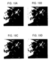
- FIG. 19 shows an output image obtained under the following conditions. That is, a step width is fixed to 2, a threshold value is fixed to 3, a shift width is fixed to 2, and the emphasizing coefficient k is sequentially changed to 0.3, 0.5, and 0.7.
- FIG. 19A shows an input image.
- FIG. 20 shows an output image obtained under the following conditions. That is, a step width is fixed to 3, a threshold value is fixed to 3, the emphasizing coefficient k is fixed to 0.7, and a shift width used to reconstruct the second derivative value is sequentially changed to 0, 1, and 2.
- FIG. 20A shows an input image.
- FIG. 20B is an output image obtained when a shift width is set to be 0
- FIG. 20C is an output image obtained when a shift width is set to be 1
- FIG. 20D is an output image obtained when a shift width is set to be 2.
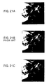
- FIG. 21 is used to compare an output obtained by a conventional contour emphasizing process method with an output image obtained by the contour emphasizing method according to this embodiment.
- FIG. 21A shows an input image having a blurred portion
- FIG. 21B is an output image obtained by the conventional method
- FIG. 21C is an output image obtained by the method according to this embodiment.
- the contours of petals are left blurred, and water drops and the like look unnatural.
- the contour portions of petals are clearly output.
- a preferable output image in which water drops and the entire surfaces of the petals did not look unnatural could be obtained.
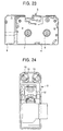
- FIGS. 22 to 25 show an embodiment of a thermal transfer printer for performing recording based on an image contour emphasizing process method according to the present invention.
- a frame 1 of the thermal transfer printer a planar platen 2 extending along the longitudinal direction of the frame 1 is arranged.
- a carriage shaft 3 located in front of the platen 2 and extending parallel to the platen 2 is supported between both the side surfaces of the frame 1.
- a carriage 4 is connected to the carriage shaft 3 such that the carriage 4 can be reciprocated along the carriage shaft 3, and a thermal head 5 is connected to the distal end portion of the carriage 4 such that the thermal head 5 can be detachably operated opposite to the platen 2.
- a ribbon cassette 6, including an ink ribbon, for guiding the ink ribbon between the thermal head 5 and the platen 2 is detachably arranged on the upper surface of the carriage 4.
- a winding bobbin 7 for winding the ink ribbon from the ribbon cassette 6 and a feeding bobbin 8 for feeding the ink ribbon are arranged on the upper surface of the carriage 4.
- an image scanner 9 is arranged on one side of the carriage 4. As shown in FIG. 24, an opening 10 is formed in a surface of the image scanner 9 opposing the platen 2. Two light-emitting members 11 constituted by lamps or the like are arranged on both the sides of the an opening 10 in the image scanner 9 such that the light-emitting members 11 point to the an opening 10.
- an image sensor unit 12 for receiving reflected light irradiated from the light-emitting members 11 onto an original to read a predetermined image is arranged.
- a carriage drive motor 13 is arranged on the lower side of one end of the frame 1 such that the output shaft of the carriage drive motor 13 pierces the upper surface of the frame 1, and a drive pulley 14 rotatably driven by the carriage drive motor 13 is fitted on the output shaft of the carriage drive motor 13.
- a coupled pulley 15 is rotatably arranged on the upper surface of the other end of the frame 1, and a carriage drive belt 16 partially connected to the lower surface of the carriage 4 is looped between the drive pulley 14 and the coupled pulley 15.
- the carriage drive motor 13 is rotatably driven to drive the ribbon cassette 6 through the drive pulley 14, so that the carriage 4 is reciprocated parallel to the platen 2 along the carriage shaft 3.
- a convey roller 17 for conveying a predetermined recording medium at a predetermined speed is arranged under the rear portion of the platen 2, and a plurality of press contact rollers 18 which are in press contact with the convey roller 17 are rotatably arranged under the convey roller 17.
- a paper-feeding unit (not shown) is arranged behind the frame 1.
- the convey roller 17 is rotatably driven, the recording medium supplied from the paper-feeding unit to a portion between the convey roller 17 and the press contact roller 18 is conveyed between the thermal head 5 and the platen 2.
- a paper-discharge roller 19 for guiding the printed recording medium is arranged above the platen 2.
- a positioning marker 20 is formed on one side of the platen 2 of the frame 1, and the positioning marker 20 is read by the image scanner 9, so that the stop position of the carriage 4 is recognized.
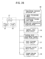
- An embodiment of a controller in a thermal transfer printer for performing recording based on the image contour emphasizing process method according to the present invention A ROM 22 in which conditions of a recording pattern corresponding to the number of gradation levels corresponding to density data such as a dither pattern, conditions required for the contour emphasizing process, and conditions such as Equations (1) to (3) for calculating the first derivative value and second derivative value of an interest pixel or output equations (4) and (5) for an emphasizing process are stored and a RAM 23 in which various data are stored are connected to a CPU 21.
- Image information read by the image scanner 14 with the predetermined number of parts obtained by dividing one pixel is supplied to the CPU 21.
- a conversion process controller 24 for transmitting a command representing a manner of processing the image information and a command representing a manner of emphasizing a contour portion is connected to the CPU 21.
- the conversion process controller 24 is designed to be switched to three read data conversion process modes, i.e., an image processing mode, a character processing mode, and a contour line emphasizing process mode.
- the conversion commands can be arbitrarily selected by a user or can be automatically selected.
- the image processing mode is a processing mode for performing selection when an original is image information such as a photograph having a half-tone image.
- the CPU 21 arbitrarily selects a predetermined number of read data from read data serving as gradation data of one pixel sent from the image scanner and constituted by N data.
- the CPU 21 calculates a density gradation value in unit of one pixel from the several read data, and stores the density gradation value as one density data in the RAM 23.
- the character processing mode is a processing mode for performing selection when an original is character information.
- the CPU 21 simply determines read data serving as gradation data of one pixel sent from the image scanner and constituted by N data as binary data of O (white) or 1 (black).
- the CPU 21 calculates the number of binary data of O (white) or 1 (black) existing in one pixel.
- the CPU 21 finally determines 0 (white) or 1 (black) of one pixel by checking whether the calculated value is larger than a predetermined number or smaller than the predetermined number, i.e., the CPU 21 determines whether this pixel is recorded or not, so that the recording data is stored in the RAM 23.
- the contour line emphasizing process mode is a process mode for, when an image in an original is blurred, performing an emphasizing process to the contour line of the image to make the contour line sharp.
- the contour line emphasizing process the above contour portion emphasizing process method according to the present invention is used. More specifically, the first derivative value and second derivative value of each interest pixel in a read original image are calculated on the basis of Equations (1) to (3) for calculation, the original image is scanned in a horizontal direction and a vertical direction to calculate a pair of pixels in which both the second derivative values (absolute values) are equal to or larger than a threshold value and the signs of both the first derivative values are equal to each other, thereby detecting a contour line.
- a second derivative value at a position shifted from the interest pixel by an arbitrary width is substituted as a second derivative value located at the interest pixel to reconstruct the secondary differential value image.
- the output value of the reconstructed secondary differential value image is substituted for the output equation (5) to calculate an output value from the interest pixel.
- the CPU 21 is designed to supply control signals to a thermal head drive circuit 25 for performing energizing control for the thermal head 10, a thermal head attachment/detachment drive circuit 26 for operating the thermal head 10 to attach or detach the thermal head 10 to/from the platen 7, an image scanner drive circuit 27 for performing drive control for the image scanner 14, and a carriage motor drive circuit 28, and a convey roller drive circuit 29, respectively.
- the present invention is not limited to the embodiments described above, and various modifications can be effected as needed.
- an image contour emphasizing process method based on the reconstructing process method, and a thermal transfer printer for performing recording based on the contour emphasizing process method the following advantages can be obtained. That is, blurring at the contour portion of an original image is corrected to form an image having a sharp contour, and a high-quality recording image can be obtained.
Landscapes
- Engineering & Computer Science (AREA)
- Physics & Mathematics (AREA)
- General Physics & Mathematics (AREA)
- Theoretical Computer Science (AREA)
- Computer Vision & Pattern Recognition (AREA)
- Facsimile Image Signal Circuits (AREA)
- Image Processing (AREA)
- Image Analysis (AREA)
Claims (5)
- Verfahren zum Verbessern eines aus Werten zweiter Ableitung bestehenden Bildes, dadurch gekennzeichnet, dass aus jedem Pixel eines Originalbilds (m,n) ein Wert der ersten Ableitung und ein Wert der zweiten Ableitung L (i, j) berechnet werden, dass das Originalbild in horizontaler Richtung (x) und in vertikaler Richtung (y) abgetastet wird, um eine Konturlinie (ST1) auf der Grundlage der Vorzeichen des Werts erster Ableitung und des Werts zweiter Ableitung zu detektieren, dass eine hervorzuhebende Zone entlang der Konturlinie in einer Richtung rechtwinklig zu einer Tangente an jedem Pixel der Konturlinie (i, j) definiert wird (ST2), und dass für jedes Pixel in der hervorzuhebenden Zone ein Wert zweite Ableitung, der sich an einer Stelle befindet, die um eine vorbestimmte Breite in einer Richtung rechtwinklig bezüglich einer Tangente an jedes Pixel an der Konturlinie befindet, als der Wert der zweiten Ableitung ersetzt wird (ST4).
- Verfahren nach Anspruch 1, dadurch gekennzeichnet, dass, wenn paarweise Konturlinien einander in einem Intervall benachbart sind, welches kleiner als eine zweite vorbestimmte Breite ist, Pixel der Konturlinien und Pixel zwischen den Konturlinien von den Pixeln, die dem Verbesserungsverfahren unterzogen werden, ausgeschlossen werden.
- Verfahren nach Anspruch 2, bei dem für jedes Pixel eines Originalbild ein entsprechender Ausgangswert eines aus Werten zweiter Ableitung bestehenden Bildes mit einem Hervorhebungskoeffizienten (k) multipliziert wird und der resultierende Wert auf den Pixelwert des Originalbilds addiert oder von diesem subtrahiert wird, um die Kontur des Originalbilds hervorzuheben.
- Thermotransferdrucker, umfassend:wobei die Steuerung dazu ausgebildet ist, einen Wert erster Ableitung und einen Wert zweiter Ableitung für jedes Pixel eines Originalbilds zu berechnen, das Originalbild in horizontaler Richtung (x) und in vertikaler Richtung zu tasten, um eine Konturlinie auf der Grundlage der Vorzeichen des Werts erster Ableitung und des Werts zweiter Ableitung zu detektieren, um eine hervorzuhebende Zone entlang der Konturlinie rechtwinklig bezüglich einer Tangente an jedem Pixel auf der Konturlinie (i, j) zu definieren, und für jedes Pixel in der hervorzuhebenden Zone einen Wert zweiter Ableitung, der sich an einer Stelle befindet, die um eine vorbestimmte Breite in einer Richtung rechtwinklig bezüglich einer Tangente jedes Pixel der Konturlinie verschoben ist, als Wert zweiter Ableitung zu ersetzen, um das aus Werten zweiter Ableitung bestehende Bild zu verbessern, um für jedes Pixel des Originalbilds einen entsprechenden Ausgangswert des verbesserten, aus Werten zweiter Ableitung bestehenden Bilds mit einem Hervorhebungskoeffizienten (k) zu multiplizieren, und um den resultierenden Wert auf den Pixelwert des Originalbilds zu addieren oder von ihm zu subtrahieren, um einen verbesserten Ausgangswert zu berechnen.einen Bildscanner (9) zum Lesen von Information eines Originalbilds;eine Steuerung (24) zum Durchführen eines Umwandlungsverfahrens für die Information des von dem Bildscanner gelesenen Originalbilds als Aufzeichnungsdaten; undeinen Aufzeichnungskopf (5) zum Durchführen einer Aufzeichnung auf der Grundlage der Aufzeichnungsdaten,
- Thermotransferdrucker nach Anspruch 4, weiterhin dadurch gekennzeichnet, dass, wenn ein Paar Konturlinien einander um ein vorbestimmtes Intervall benachbart sind, welches kieiner ist als eine zweite vorbestimmte Breite in dem Originalbild, eine Steuerung eine solche Steuerung durchführt bezüglich der Pixel der Konturlinien, dass Pixel der Konturlinien und Pixel zwischen den Konturlinien ausgeschlossen werden von den Pixeln, die einem Verbesserungsverfahren für ein Bild zweiter Ableitungswerte unterzogen werden, und ein Wert zweiter Ableitung an einer jeweiligen Pixelposition direkt als der entsprechende Ausgangswert des Bilds aus Werten zweiter Ableitung verwendet wird, für jedes Pixel des Originalbilds der entsprechende Ausgangswert des Bilds aus Werten zweiter Ableitung mit dem Hervorhebungskoeffizienten multipliziert wird, und der resultierende Wert auf den Pixelwert des Originalbilds addiert oder von diesem subtrahiert wird, um einen Ausgangswert zu berechnen.
Applications Claiming Priority (3)
| Application Number | Priority Date | Filing Date | Title |
|---|---|---|---|
| JP28422097 | 1997-09-09 | ||
| JP28422097A JP3635194B2 (ja) | 1997-09-09 | 1997-09-09 | 2次微分値画像の再構成処理方法およびこの再構成処理方法に基づく画像の輪郭強調処理方法ならびにこの輪郭強調処理方法に基づく記録を行う熱転写プリンタ |
| JP284220/97 | 1997-09-09 |
Publications (2)
| Publication Number | Publication Date |
|---|---|
| EP0902393A1 EP0902393A1 (de) | 1999-03-17 |
| EP0902393B1 true EP0902393B1 (de) | 2004-09-29 |
Family
ID=17675735
Family Applications (1)
| Application Number | Title | Priority Date | Filing Date |
|---|---|---|---|
| EP98306515A Expired - Lifetime EP0902393B1 (de) | 1997-09-09 | 1998-08-14 | Bildverarbeitungsverfahren und thermischer Übertragungsdrucker |
Country Status (4)
| Country | Link |
|---|---|
| US (1) | US6268933B1 (de) |
| EP (1) | EP0902393B1 (de) |
| JP (1) | JP3635194B2 (de) |
| DE (1) | DE69826597T2 (de) |
Families Citing this family (6)
| Publication number | Priority date | Publication date | Assignee | Title |
|---|---|---|---|---|
| KR100444997B1 (ko) * | 2002-02-21 | 2004-08-21 | 삼성전자주식회사 | 윤곽 보정 방법 및 이에 적합한 장치 |
| US20050163401A1 (en) * | 2004-01-28 | 2005-07-28 | Techwell Inc. | Display image enhancement apparatus and method using adaptive interpolation with correlation |
| KR100901354B1 (ko) * | 2007-05-31 | 2009-06-05 | 주식회사 코아로직 | 영상의 에지 보정장치 및 그 방법 |
| US20090010562A1 (en) * | 2007-07-03 | 2009-01-08 | Samsung Electronics Co., Ltd. | Method of revising edge region and image forming device using the same |
| US8573725B2 (en) | 2010-08-16 | 2013-11-05 | Xerox Corporation | System and method for correcting stitch error in a staggered printhead assembly |
| US8849057B2 (en) * | 2011-05-19 | 2014-09-30 | Foveon, Inc. | Methods for digital image sharpening with noise amplification avoidance |
Family Cites Families (8)
| Publication number | Priority date | Publication date | Assignee | Title |
|---|---|---|---|---|
| US3641268A (en) * | 1969-07-24 | 1972-02-08 | Us Navy | Real-time image contrast and edge sharpness enhancing apparatus |
| US5774572A (en) * | 1984-12-20 | 1998-06-30 | Orbotech Ltd. | Automatic visual inspection system |
| JP2589298B2 (ja) * | 1987-01-28 | 1997-03-12 | キヤノン株式会社 | 符号化画像データの復号化装置 |
| JPH055725Y2 (de) * | 1987-02-06 | 1993-02-15 | ||
| JPH02162475A (ja) * | 1988-12-15 | 1990-06-22 | Dainippon Screen Mfg Co Ltd | 画像輪郭修正方法 |
| JP2574923B2 (ja) * | 1990-04-10 | 1997-01-22 | 大日本スクリーン製造株式会社 | 輪郭強調方法および画像処理装置 |
| JPH07107273A (ja) | 1993-10-07 | 1995-04-21 | Canon Inc | 画像処理装置及び方法 |
| JPH08212341A (ja) | 1995-02-03 | 1996-08-20 | Nippon Hihakai Kensa Kk | 放射線透過写真の画像処理方法及びその装置 |
-
1997
- 1997-09-09 JP JP28422097A patent/JP3635194B2/ja not_active Expired - Fee Related
-
1998
- 1998-08-14 EP EP98306515A patent/EP0902393B1/de not_active Expired - Lifetime
- 1998-08-14 DE DE69826597T patent/DE69826597T2/de not_active Expired - Fee Related
- 1998-09-08 US US09/149,528 patent/US6268933B1/en not_active Expired - Fee Related
Also Published As
| Publication number | Publication date |
|---|---|
| EP0902393A1 (de) | 1999-03-17 |
| US6268933B1 (en) | 2001-07-31 |
| DE69826597D1 (de) | 2004-11-04 |
| JP3635194B2 (ja) | 2005-04-06 |
| DE69826597T2 (de) | 2005-11-17 |
| JPH1185977A (ja) | 1999-03-30 |
Similar Documents
| Publication | Publication Date | Title |
|---|---|---|
| US6227725B1 (en) | Text enhancement for color and gray-scale documents | |
| US7068852B2 (en) | Edge detection and sharpening process for an image | |
| EP1310912B1 (de) | Bildverarbeitungsverfahren, -vorrichtung und -system | |
| US7298380B2 (en) | Image processing method and apparatus for white eye correction | |
| US7633650B2 (en) | Apparatus and method for processing binary image produced by error diffusion according to character or line drawing detection | |
| US7486317B2 (en) | Image processing method and apparatus for red eye correction | |
| KR950009694B1 (ko) | 정보기록장치 | |
| JP4890974B2 (ja) | 画像処理装置、及び画像処理方法 | |
| JPH04219067A (ja) | 画像処理方法 | |
| EP1530154A2 (de) | Verfahren und Vorrichtung zur Bildschärfung | |
| EP0740456B1 (de) | Bildverarbeitung zur Bestimmung und Änderung von den Hintergrund einer abgetasteten Dokumentenvorlage darstellenden Dichtewerten. | |
| US8248662B2 (en) | Image forming apparatus and method thereof | |
| US7283673B2 (en) | Image processing method and apparatus | |
| EP0902393B1 (de) | Bildverarbeitungsverfahren und thermischer Übertragungsdrucker | |
| DE69528324T2 (de) | Bildverarbeitungsvorrichtung mit Bildinhaltsdiskriminierung | |
| NL1012708C2 (nl) | Afdrukken van digitale kleurenbeelden met locaal aangepaste halftoning. | |
| US7359566B2 (en) | Bright point detecting method and computer program product for conducting the bright point detecting method | |
| US5926258A (en) | Method of reproducing transparent masters | |
| JP4189654B2 (ja) | 画像処理装置 | |
| JP3976810B2 (ja) | カラー画像の明るさ調整方法および装置 | |
| US7295344B2 (en) | Image processing method and image processing apparatus, program and recording medium, and image forming apparatus | |
| JP4284604B2 (ja) | コントラスト調整方法及びこの方法を実施するコントラスト調整装置 | |
| JP4005243B2 (ja) | 画像処理装置 | |
| JP3954144B2 (ja) | 画像処理方法及び装置 | |
| JP2729278B2 (ja) | 画像の2値化表現方法 |
Legal Events
| Date | Code | Title | Description |
|---|---|---|---|
| PUAI | Public reference made under article 153(3) epc to a published international application that has entered the european phase |
Free format text: ORIGINAL CODE: 0009012 |
|
| AK | Designated contracting states |
Kind code of ref document: A1 Designated state(s): DE FR GB |
|
| AX | Request for extension of the european patent |
Free format text: AL;LT;LV;MK;RO;SI |
|
| 17P | Request for examination filed |
Effective date: 19990121 |
|
| AKX | Designation fees paid |
Free format text: DE FR GB |
|
| 17Q | First examination report despatched |
Effective date: 20020819 |
|
| GRAP | Despatch of communication of intention to grant a patent |
Free format text: ORIGINAL CODE: EPIDOSNIGR1 |
|
| GRAS | Grant fee paid |
Free format text: ORIGINAL CODE: EPIDOSNIGR3 |
|
| GRAA | (expected) grant |
Free format text: ORIGINAL CODE: 0009210 |
|
| AK | Designated contracting states |
Kind code of ref document: B1 Designated state(s): DE FR GB |
|
| REG | Reference to a national code |
Ref country code: GB Ref legal event code: FG4D |
|
| REF | Corresponds to: |
Ref document number: 69826597 Country of ref document: DE Date of ref document: 20041104 Kind code of ref document: P |
|
| PLBE | No opposition filed within time limit |
Free format text: ORIGINAL CODE: 0009261 |
|
| STAA | Information on the status of an ep patent application or granted ep patent |
Free format text: STATUS: NO OPPOSITION FILED WITHIN TIME LIMIT |
|
| ET | Fr: translation filed | ||
| PG25 | Lapsed in a contracting state [announced via postgrant information from national office to epo] |
Ref country code: GB Free format text: LAPSE BECAUSE OF NON-PAYMENT OF DUE FEES Effective date: 20050814 |
|
| 26N | No opposition filed |
Effective date: 20050630 |
|
| PGFP | Annual fee paid to national office [announced via postgrant information from national office to epo] |
Ref country code: DE Payment date: 20051025 Year of fee payment: 8 |
|
| GBPC | Gb: european patent ceased through non-payment of renewal fee |
Effective date: 20050814 |
|
| PG25 | Lapsed in a contracting state [announced via postgrant information from national office to epo] |
Ref country code: FR Free format text: LAPSE BECAUSE OF NON-PAYMENT OF DUE FEES Effective date: 20060428 |
|
| REG | Reference to a national code |
Ref country code: FR Ref legal event code: ST Effective date: 20060428 |
|
| PG25 | Lapsed in a contracting state [announced via postgrant information from national office to epo] |
Ref country code: DE Free format text: LAPSE BECAUSE OF NON-PAYMENT OF DUE FEES Effective date: 20070301 |