EP0902303B1 - Dispositif pour la détection des objets avant un organe de commande d'une machine - Google Patents
Dispositif pour la détection des objets avant un organe de commande d'une machine Download PDFInfo
- Publication number
- EP0902303B1 EP0902303B1 EP98116427A EP98116427A EP0902303B1 EP 0902303 B1 EP0902303 B1 EP 0902303B1 EP 98116427 A EP98116427 A EP 98116427A EP 98116427 A EP98116427 A EP 98116427A EP 0902303 B1 EP0902303 B1 EP 0902303B1
- Authority
- EP
- European Patent Office
- Prior art keywords
- plate
- radiation
- light gathering
- light
- gathering plate
- Prior art date
- Legal status (The legal status is an assumption and is not a legal conclusion. Google has not performed a legal analysis and makes no representation as to the accuracy of the status listed.)
- Expired - Lifetime
Links
Images

Classifications
-
- G—PHYSICS
- G07—CHECKING-DEVICES
- G07F—COIN-FREED OR LIKE APPARATUS
- G07F19/00—Complete banking systems; Coded card-freed arrangements adapted for dispensing or receiving monies or the like and posting such transactions to existing accounts, e.g. automatic teller machines
- G07F19/20—Automatic teller machines [ATMs]
-
- G—PHYSICS
- G01—MEASURING; TESTING
- G01V—GEOPHYSICS; GRAVITATIONAL MEASUREMENTS; DETECTING MASSES OR OBJECTS; TAGS
- G01V8/00—Prospecting or detecting by optical means
- G01V8/10—Detecting, e.g. by using light barriers
- G01V8/12—Detecting, e.g. by using light barriers using one transmitter and one receiver
- G01V8/14—Detecting, e.g. by using light barriers using one transmitter and one receiver using reflectors
-
- G—PHYSICS
- G07—CHECKING-DEVICES
- G07F—COIN-FREED OR LIKE APPARATUS
- G07F19/00—Complete banking systems; Coded card-freed arrangements adapted for dispensing or receiving monies or the like and posting such transactions to existing accounts, e.g. automatic teller machines
- G07F19/20—Automatic teller machines [ATMs]
- G07F19/201—Accessories of ATMs
-
- G—PHYSICS
- G07—CHECKING-DEVICES
- G07F—COIN-FREED OR LIKE APPARATUS
- G07F19/00—Complete banking systems; Coded card-freed arrangements adapted for dispensing or receiving monies or the like and posting such transactions to existing accounts, e.g. automatic teller machines
- G07F19/20—Automatic teller machines [ATMs]
- G07F19/205—Housing aspects of ATMs
-
- G—PHYSICS
- G07—CHECKING-DEVICES
- G07F—COIN-FREED OR LIKE APPARATUS
- G07F9/00—Details other than those peculiar to special kinds or types of apparatus
- G07F9/02—Devices for alarm or indication, e.g. when empty; Advertising arrangements in coin-freed apparatus
-
- G—PHYSICS
- G07—CHECKING-DEVICES
- G07G—REGISTERING THE RECEIPT OF CASH, VALUABLES, OR TOKENS
- G07G3/00—Alarm indicators, e.g. bells
- G07G3/006—False operation
-
- H—ELECTRICITY
- H01—ELECTRIC ELEMENTS
- H01H—ELECTRIC SWITCHES; RELAYS; SELECTORS; EMERGENCY PROTECTIVE DEVICES
- H01H2239/00—Miscellaneous
- H01H2239/032—Anti-tamper
Definitions
- the invention relates to an arrangement for recognizing Objects in front of a control element of an electronic Device, especially in front of a keyboard Self-service device can be attached after the preamble of claim 1.
- Self-operated electronic devices in particular vending machines such as cash dispensers and self-service terminals are increasingly subject to attack by unauthorized people User, with the aim of unauthorized access to the services of the machine.
- Items become known, for example in front of a card reader a replica of a card reader mouthpiece the card is placed without authorization retains.
- PIN numbers spy out by using the PIN keyboard with a Sensor device for key operations was built over.
- DE 42 40 804 A1 describes a device for recognizing the position and / or for measuring the width of a record carrier described in which a focused light beam from a light source over the record carrier to be led. When leaving the record carrier the light beam hits an optical fiber, in which he triggers fluorescent radiation. This is from a photo detector, the output signal of which Absence of a record carrier on the corresponding one Location signaled.
- the object of the invention is a simple arrangement of the Specify the type mentioned for the protection of controls, is particularly suitable for keyboards.
- a housing surface surrounding the control element of the device at least partially by one Cover plate made of translucent material covered.
- the at least on part of the light collecting plate surface incident radiation is direct or than fluorescence radiation excited by it into an inside of the light collecting plate running beam path deflected and picked up by the sensor.
- the All or part of the surface of the light collecting plate covered a "superstructure” the intensity changes of the radiation picked up by the sensor, which is an indication evaluated for the attachment of an unauthorized "superstructure” can be.
- a particular advantage of the invention The order can be seen in the fact that it is retrospective easily and without mechanical change to the electronic Device can be attached to this. This can for example by sticking the light collecting plate on the housing surface surrounding the control element to be protected respectively.
- a second plate is placed vertically, in which is embedded at least one sensor.
- the second plate over a side edge of the light collecting plate arranged on the side facing the device the light collecting plate is at 45 ° to the outer surface chamfered edge.
- the second plate arranged over a wedge-shaped groove the into the surface of the light collecting plate facing the device is embedded, with a groove wall with the second plate encloses an angle of 45 °.
- the second 45 ° inclined surface serves in a manner known per se Beam deflection from the light collecting plate into the second plate.
- the light collecting plate has at least one Light deflecting surface deflecting radiation deflecting surface on which the radiation is in a ray path redirected within the light collecting plate.
- the redirecting Surface can be formed, for example, that a side of the light collecting plate facing the device edge chamfered by 45 °.
- the Device facing surface of the light collecting plate a wedge-shaped Groove inserted, the one groove wall with the after outside surface of the light collecting plate at an angle of 45 °.
- the deflecting surface can either mirrored or polished. In both cases occurs a reflection of the radiation.
- the Light collecting plate made of fluorescent colored acrylic glass manufactured. Radiation hitting their surface excites the plate material to fluorescent radiation due to the total reflection on the plate surfaces remains inside the light collecting plate and emerges from this on one side surface. In this The case can dispense with a beam deflecting surface the entire surface of the light collecting plate the radiation that hits them and it can therefore cover by a "superstructure" can be detected.
- the second plate consists of any radiopaque material and has a channel for receiving the at least one sensor on the starting from the light collecting plate normal to the surface the light collecting plate extends, or the second Plate is made of radiation-conducting material.
- the radiation arrives after it has been deflected through the second surface inclined by 45 ° onto the Sensor.
- the second plate can be used in a particularly advantageous manner at the same time as one arranged on one side of a keyboard Serve as a privacy screen. This is convenient attach a privacy screen on both sides of the keyboard, one or both of which have a sensor can contain.
- the claimed arrangement is not as straightforward Device for recognizing objects that have been attached without authorization to identify. This is still encouraged if an invisible light as the light source, in particular Radiation source emitting infrared light is used becomes.
- the invisible light can be emitted as permanent light become.
- the use is particularly advantageous of pulsed or modulated light as this of evaluation electronics with coordinated Passage characteristic particularly light from the radiation to be distinguished from other light sources. Thereby the detection reliability for "superstructures" is even further elevated.
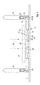
- Fig. 1 is a control surface 1 of an electronic Device shown, in which a keyboard 10 installed is.
- a keyboard 10 installed is on the control surface 1 .
- Arrangement 12 for recognizing objects 14 according to a first embodiment of the invention.
- the arrangement 12 contains a light collecting plate 16 translucent material into which the buttons 18 the keyboard 10 leaving openings 20 molded are.
- Right and left of a middle opening 20 ' is in the side of the light collecting plate facing the control surface 1 16 each have a first wedge-shaped groove 22 or 22 'embedded, the one groove wall 24 with that of the control surface 1 pioneering outer surface of the light collecting plate 16 includes an angle of 45 ° and their other groove wall 26 inclined at any angle can be.
- a second wedge-shaped groove 28 or 28 ' one of which has a groove wall 30 with that of the control surface 1 technological surface of the light collecting plate 16 in turn Includes 45 ° angle.
- the inclined groove walls 24, 30 of the grooves 22, 28 and 22 ', 28' face each other.
- a second plate 32, 32' is placed on each.
- a channel 34 formed from the light collecting plate 16 goes out and normal to their surface extends.
- a radiation sensor 36 is in the channel 34 built in with a measuring and not shown Evaluation electronics for radiation intensity connected is.
- the arrangement 12 for recognizing objects 14 works as follows: A radiation source, not shown illuminates by means of direct and indirect the ceiling of an installation room of the device Radiation 38 on the control surface 1 of the device. The radiation 38 is received by the light collecting plate 16 and on the inclined groove wall 24 of the first groove 22 or 22 'in a parallel to the surface of the light collecting plate 16 directed beam path deflected. The Radiation 38 finally strikes the inclined groove wall 30 of the second groove 28 or 28 ', where they in the direction of is deflected second plates 32 and 32 'and there the radiation sensors 36 hits. Now is a Item 14 such as an impermissible superstructure on the Put on keyboard 10, the radiation 38 through this at least in part from the light collecting plate 16 kept away. This reduction in radiation intensity is detected by the radiation sensor 36 and by the measuring and evaluation electronics reported.
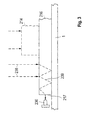
- FIG. 2 is again an operating surface 1 of an electronic Device shown, in which a keyboard 10 installed is.
- the keyboard 10 surrounding arrangement 112 for recognizing objects according to a second embodiment of the invention placed.
- the arrangement 112 consists of two sub-arrangements 112 ', 112 "that come together in a row of middle buttons 118. Both sub-assemblies 112 ', 112 "are built in mirror image, which is why only one below Partial arrangement is described. It contains a light collecting plate 116 made of translucent material, in the the key buttons 119 of the keyboard 110 leave openings 120 are molded. On each button 119 is a plunger 140 is placed on the one above Breakthrough 120 penetrated. To those on the button 119 a collar 142 is formed on the lying side of the plunger 140, the one on the edge of a reduced in cross section Section 144 of the opening 120 abuts and so the Tappet 140 holds captive in the opening 120.
- the outer side edge 146 in FIG. 2 and the one at middle row of keys 118 located side edge 148 of the Light collecting plate 116 are chamfered so that they with the surface of the light collecting plate pointing away from the control surface 1 116 each enclose an angle of 45 °.
- the inclined surfaces of the side edges 146, 148 are facing each other.
- Above the sloping surface of the outward side edge 146 is one of the second Side plate 32, 32 'in the exemplary embodiment according to FIG. 1 corresponding second side plate 132 arranged.
- the arrangement according to Fig. 2 has in addition to the captivity the plunger 140 has the advantage over that of FIG. 1, that a chamfer on the edge of the light collecting plate easier is to produce as a groove in this.
- the mode of action corresponds to that described above.
- the light collecting plate 216 can have openings 20 according to FIG. 1 or 120 according to FIG.
- a second plate 32 can also be placed on it (Fig. 1) or 132 (Fig. 2) are placed. In this Case must have a radiation deflecting surface under it accordingly the inclined groove wall 30 (Fig. 1) or the chamfered Side edge 146 (Fig. 2) can be provided.
- the arrangement 12 of the embodiment can 1 with plungers 140 or the arrangement 112 of the embodiment of FIG. 2 with simple Breakthroughs 20 are provided above the key buttons 118 his.
Landscapes
- Physics & Mathematics (AREA)
- General Physics & Mathematics (AREA)
- Business, Economics & Management (AREA)
- Accounting & Taxation (AREA)
- Finance (AREA)
- Life Sciences & Earth Sciences (AREA)
- General Life Sciences & Earth Sciences (AREA)
- Geophysics (AREA)
- Input From Keyboards Or The Like (AREA)
- Position Input By Displaying (AREA)
- Supply And Installment Of Electrical Components (AREA)
- Die Bonding (AREA)
- Air Conditioning Control Device (AREA)
- Length Measuring Devices By Optical Means (AREA)
- Pinball Game Machines (AREA)
- Machine Tool Sensing Apparatuses (AREA)
- Investigating Strength Of Materials By Application Of Mechanical Stress (AREA)
- Manipulator (AREA)
- Geophysics And Detection Of Objects (AREA)
Claims (8)
- Dispositif (12) de reconnaissance d'objets (14, 214), qui peuvent être placés devant un élément de commande d'un appareil électronique, notamment devant un clavier (10, 110) d'un appareil de libre service, comprenant au moins un capteur (36, 236) optique qui est prévu pour recevoir le rayonnement (38, 238) d'une source lumineuse, un objet (14, 214) placé devant l'élément (10, 110) de commande diminuant l'intensité du rayonnement (38, 239) arrivant sur le capteur (36, 236),
caractériséen ce qu'une surface (1) du boítier de l'appareil entourant l'élément (10, 110) de commande est recouverte au moins en partie par une plaque (16, 116, 216) collectrice de lumière en matériau transparent à la lumière,en ce que le rayonnement (38, 238) arrivant au moins sur une partie de la surface de la plaque (16, 116, 216) collectrice de lumière est dévié directement ou en tant que rayonnement (239) fluorescent provoqué par celle-ci vers une marche des rayons s'étendant à l'intérieur de la plaque (16, 116, 216) collectrice de lumière,en ce que le capteur (36, 236) est monté sur la plaque (16, 116, 216) collectrice de lumière de telle manière qu'il peut recevoir un rayonnement (38, 239) s'étendant dans cette dernière,et en ce qu'il est placé sur la face de la plaque (16, 116) collectrice de lumière éloignée de l'appareil une deuxième plaque (32, 132) en saillie de celle-ci dans laquelle le au moins un capteur (36) est encastré et dans la direction de laquelle le rayonnement (38) s'étendant dans la plaque (16, 116) collectrice de lumière est dévié, la deuxième plaque (132) étant montée à cet effet au-dessus d'un bord (146) latéral de la plaque (116) collectrice de lumière qui comporte du côté de la plaque (116) collectrice de lumière tournée vers l'appareil un bord biseauté à 45°,
ou la deuxième plaque (32) est disposée au-dessus d'une rainure (28) cunéiforme qui est ménagée dans la plaque (16) collectrice de lumière, une paroi (30) de la rainure (28) faisant un angle de 45° avec la deuxième plaque (32). - Dispositif suivant la revendication 1, caractérisé en ce que la plaque collectrice de lumière comporte au moins une surface qui dévie un rayonnement arrivant sur la plaque collectrice et qui dévie le rayonnement vers la marche des rayons à l'intérieur de la plaque collectrice de lumière.
- Dispositif suivant la revendication 2, caractérisé en ce que le côté de la plaque (116) collectrice de lumière tourné vers l'appareil comporte un bord (148) biseauté à 45° ou en ce qu'il est ménagé dans sa face toumée vers l'appareil une rainure (22) cunéiforme dont une paroi (24) de rainure fait un angle de 45° avec la surface de la plaque (16) collectrice de lumière tournée vers l'extérieur.
- Dispositif suivant la revendication 1, caractérisé en ce que la plaque (216) collectrice de lumière est fabriquée en verre acrylique de couleur fluorescente.
- Dispositif suivant l'une des revendications 1 à 4, caractérisé en ce que la deuxième plaque (32) comporte un canal (34) pour la réception du moins un capteur (36) qui s'étend de la plaque (16) collectrice de lumière perpendiculairement jusqu'à la surface de la plaque (16) collectrice de lumière.
- Dispositif suivant l'une des revendications 1 à 5, caractérisé en ce que la deuxième plaque est en un matériau conducteur du rayonnement.
- Dispositif suivant l'une des revendications 1 à 6, caractérisé en ce que la deuxième plaque est une joue (32, 132) de protection visuelle disposée d'un côté d'un clavier.
- Dispositif suivant l'une des revendications précédentes,
caractérisé en ce que la source lumineuse est une source de lumière infrarouge foumissant une lumière ininterrompue, une lumière modulée ou des impulsions lumineuses.
Applications Claiming Priority (2)
| Application Number | Priority Date | Filing Date | Title |
|---|---|---|---|
| DE19739771 | 1997-09-10 | ||
| DE19739771A DE19739771A1 (de) | 1997-09-10 | 1997-09-10 | Anordnung zum Erkennen von vor einem Bedienelement eines Gerätes angebrachten Gegenständen |
Publications (3)
| Publication Number | Publication Date |
|---|---|
| EP0902303A2 EP0902303A2 (fr) | 1999-03-17 |
| EP0902303A3 EP0902303A3 (fr) | 1999-06-02 |
| EP0902303B1 true EP0902303B1 (fr) | 2002-01-02 |
Family
ID=7841895
Family Applications (1)
| Application Number | Title | Priority Date | Filing Date |
|---|---|---|---|
| EP98116427A Expired - Lifetime EP0902303B1 (fr) | 1997-09-10 | 1998-08-31 | Dispositif pour la détection des objets avant un organe de commande d'une machine |
Country Status (4)
| Country | Link |
|---|---|
| EP (1) | EP0902303B1 (fr) |
| AT (1) | ATE211556T1 (fr) |
| DE (2) | DE19739771A1 (fr) |
| ES (1) | ES2170986T3 (fr) |
Families Citing this family (8)
| Publication number | Priority date | Publication date | Assignee | Title |
|---|---|---|---|---|
| GB0414578D0 (en) | 2004-06-30 | 2004-08-04 | Ncr Int Inc | Self-service terminal |
| DE102004035224B4 (de) * | 2004-07-21 | 2006-11-23 | Wincor Nixdorf International Gmbh | Selbstbedienungsgerät mit Manipulationserkennung |
| GB2421300A (en) * | 2004-12-18 | 2006-06-21 | Nigel Leonard Mason | Anti-skimming device for use with cash machines |
| DE102008014324A1 (de) | 2008-03-14 | 2009-09-17 | Wincor Nixdorf International Gmbh | Selbstbedienungsgerät |
| DE102008023582A1 (de) * | 2008-05-14 | 2009-11-19 | Wincor Nixdorf International Gmbh | Geldausgabeautomat |
| DE202009006642U1 (de) * | 2009-04-03 | 2010-08-26 | Behr, Thomas | Vorrichtung zur Berechtigungsüberprüfung |
| PL2450823T3 (pl) * | 2010-11-04 | 2013-11-29 | Keba Ag | Wykrywanie obcego ciała umieszczonego w bliskim obszarze środka do wprowadzania stosowanego do uwierzytelniania |
| EP3736783B1 (fr) * | 2019-05-09 | 2023-09-13 | Diebold Nixdorf Systems GmbH | Distributeur automatique de billets |
Family Cites Families (7)
| Publication number | Priority date | Publication date | Assignee | Title |
|---|---|---|---|---|
| US4175231A (en) * | 1976-09-28 | 1979-11-20 | Canon Kabushiki Kaisha | Device for detecting a moving body |
| FR2588385B1 (fr) * | 1985-10-07 | 1988-03-18 | Smh Alcatel | Detecteur de passage d'objets plats |
| US4958067A (en) * | 1988-01-25 | 1990-09-18 | Alpine Electronics Inc. | Method and apparatus for optically detecting the location of a control object in a control panel recess |
| JPH05341132A (ja) * | 1992-06-12 | 1993-12-24 | Fujitsu Ltd | 面光源ユニット |
| DE4240804C2 (de) * | 1992-12-01 | 1995-08-17 | Mannesmann Ag | Einrichtung zum Erkennen der Lage und/oder zum Messen der Breite eines Aufzeichnungsträgers |
| DE19605092A1 (de) * | 1996-02-12 | 1997-08-14 | Siemens Nixdorf Inf Syst | Ultraschall-Tastaturschutz |
| DE19605102A1 (de) * | 1996-02-12 | 1997-08-14 | Siemens Nixdorf Inf Syst | Infrarot-Sicherungssystem |
-
1997
- 1997-09-10 DE DE19739771A patent/DE19739771A1/de not_active Withdrawn
-
1998
- 1998-08-31 DE DE59802787T patent/DE59802787D1/de not_active Expired - Lifetime
- 1998-08-31 ES ES98116427T patent/ES2170986T3/es not_active Expired - Lifetime
- 1998-08-31 AT AT98116427T patent/ATE211556T1/de not_active IP Right Cessation
- 1998-08-31 EP EP98116427A patent/EP0902303B1/fr not_active Expired - Lifetime
Also Published As
| Publication number | Publication date |
|---|---|
| EP0902303A2 (fr) | 1999-03-17 |
| DE19739771A1 (de) | 1999-03-11 |
| DE59802787D1 (de) | 2002-02-28 |
| ATE211556T1 (de) | 2002-01-15 |
| EP0902303A3 (fr) | 1999-06-02 |
| ES2170986T3 (es) | 2002-08-16 |
Similar Documents
| Publication | Publication Date | Title |
|---|---|---|
| DE102004035224B4 (de) | Selbstbedienungsgerät mit Manipulationserkennung | |
| DE4423005C1 (de) | Eingabevorrichtung für einen Computer | |
| DE69726132T2 (de) | Prüfung von sicherheitsdokumenten | |
| DE3700856A1 (de) | Optoelektronische tastatur | |
| DE3146152C2 (fr) | ||
| EP2394209B1 (fr) | Surface de détection | |
| EP1154229B1 (fr) | Dispositif pour l'évaluation quantitative de l'alignement de deux pièces de machine, des outils ou similaires | |
| EP0902303B1 (fr) | Dispositif pour la détection des objets avant un organe de commande d'une machine | |
| EP1813961B1 (fr) | Dispositif destiné à la surveillance optoélectronique d'objets | |
| EP2422328B1 (fr) | Terminal libre-service équipé d'au moins une caméra permettant d'identifier les tentatives de manoeuvres frauduleuses | |
| CH633103A5 (de) | Einrichtung zur selbsttaetigen identifizierung und registrierung von flaschen. | |
| EP0032368A1 (fr) | Carte de données | |
| DE19839977A1 (de) | Geldkassettenanordnung | |
| EP1810405B1 (fr) | Arrangement comprenant un plan de travail et une plaque en vitrocéramique arrangée dedans | |
| WO1999041713A1 (fr) | Procede de surveillance du processus d'exploitation d'appareils et dispositif de libre-service dont la surveillance est assuree a l'aide dudit procede | |
| EP0262416B1 (fr) | Barrière lumineuse à réflexion autosurveillante | |
| WO2009138187A1 (fr) | Distributeur automatique de billets | |
| EP0666393A1 (fr) | Système de clef et zylindre de verrouillage ainsi que système d'identification | |
| DE2746800C2 (de) | Anordnung zum Lichtempfang und zur Lichtreflexion, insbesondere für Schußsimulationszwecke | |
| EP1100058A1 (fr) | Composant électronique et méthode pour la protection d'un circuit intégré inclus dans ce composant | |
| EP0494617A2 (fr) | Dispositif d'identification sans contact d'objects | |
| EP3734492B1 (fr) | Lecteur de cartes à détection d'attaque de correcteurs de champ magnétique | |
| DE3938995C1 (en) | Card-operated security system - has coded strips applied to both sides of card and no more than one aligned lamp sensor pair | |
| EP2691840A1 (fr) | Surface d'entrée constituée d'une surface d'affichage et d'une surface de détecteur photosensible, et destinée à une installation de traitement de données | |
| DE102007014177A1 (de) | Modulares Merkmal für Oberflächen von Selbstbedienungssystemen |
Legal Events
| Date | Code | Title | Description |
|---|---|---|---|
| PUAI | Public reference made under article 153(3) epc to a published international application that has entered the european phase |
Free format text: ORIGINAL CODE: 0009012 |
|
| AK | Designated contracting states |
Kind code of ref document: A2 Designated state(s): AT BE CH DE ES FR GB IE IT LI NL PT SE |
|
| AX | Request for extension of the european patent |
Free format text: AL;LT;LV;MK;RO;SI |
|
| PUAL | Search report despatched |
Free format text: ORIGINAL CODE: 0009013 |
|
| AK | Designated contracting states |
Kind code of ref document: A3 Designated state(s): AT BE CH CY DE DK ES FI FR GB GR IE IT LI LU MC NL PT SE |
|
| AX | Request for extension of the european patent |
Free format text: AL;LT;LV;MK;RO;SI |
|
| 17P | Request for examination filed |
Effective date: 19991005 |
|
| AKX | Designation fees paid |
Free format text: AT BE CH DE ES FR GB IE IT LI NL PT SE |
|
| 17Q | First examination report despatched |
Effective date: 20000329 |
|
| RAP1 | Party data changed (applicant data changed or rights of an application transferred) |
Owner name: WINCOR NIXDORF GMBH & CO KG |
|
| GRAG | Despatch of communication of intention to grant |
Free format text: ORIGINAL CODE: EPIDOS AGRA |
|
| GRAG | Despatch of communication of intention to grant |
Free format text: ORIGINAL CODE: EPIDOS AGRA |
|
| GRAH | Despatch of communication of intention to grant a patent |
Free format text: ORIGINAL CODE: EPIDOS IGRA |
|
| GRAH | Despatch of communication of intention to grant a patent |
Free format text: ORIGINAL CODE: EPIDOS IGRA |
|
| GRAA | (expected) grant |
Free format text: ORIGINAL CODE: 0009210 |
|
| REG | Reference to a national code |
Ref country code: GB Ref legal event code: IF02 |
|
| AK | Designated contracting states |
Kind code of ref document: B1 Designated state(s): AT BE CH DE ES FR GB IE IT LI NL PT SE |
|
| PG25 | Lapsed in a contracting state [announced via postgrant information from national office to epo] |
Ref country code: NL Free format text: LAPSE BECAUSE OF FAILURE TO SUBMIT A TRANSLATION OF THE DESCRIPTION OR TO PAY THE FEE WITHIN THE PRESCRIBED TIME-LIMIT Effective date: 20020102 Ref country code: IT Free format text: LAPSE BECAUSE OF FAILURE TO SUBMIT A TRANSLATION OF THE DESCRIPTION OR TO PAY THE FEE WITHIN THE PRESCRIBED TIME-LIMIT;WARNING: LAPSES OF ITALIAN PATENTS WITH EFFECTIVE DATE BEFORE 2007 MAY HAVE OCCURRED AT ANY TIME BEFORE 2007. THE CORRECT EFFECTIVE DATE MAY BE DIFFERENT FROM THE ONE RECORDED. Effective date: 20020102 Ref country code: IE Free format text: LAPSE BECAUSE OF FAILURE TO SUBMIT A TRANSLATION OF THE DESCRIPTION OR TO PAY THE FEE WITHIN THE PRESCRIBED TIME-LIMIT Effective date: 20020102 |
|
| REF | Corresponds to: |
Ref document number: 211556 Country of ref document: AT Date of ref document: 20020115 Kind code of ref document: T |
|
| REG | Reference to a national code |
Ref country code: CH Ref legal event code: EP |
|
| REG | Reference to a national code |
Ref country code: IE Ref legal event code: FG4D Free format text: GERMAN |
|
| REF | Corresponds to: |
Ref document number: 59802787 Country of ref document: DE Date of ref document: 20020228 |
|
| PG25 | Lapsed in a contracting state [announced via postgrant information from national office to epo] |
Ref country code: PT Free format text: LAPSE BECAUSE OF FAILURE TO SUBMIT A TRANSLATION OF THE DESCRIPTION OR TO PAY THE FEE WITHIN THE PRESCRIBED TIME-LIMIT Effective date: 20020402 |
|
| GBT | Gb: translation of ep patent filed (gb section 77(6)(a)/1977) |
Effective date: 20020327 |
|
| NLV1 | Nl: lapsed or annulled due to failure to fulfill the requirements of art. 29p and 29m of the patents act | ||
| ET | Fr: translation filed | ||
| REG | Reference to a national code |
Ref country code: ES Ref legal event code: FG2A Ref document number: 2170986 Country of ref document: ES Kind code of ref document: T3 |
|
| REG | Reference to a national code |
Ref country code: IE Ref legal event code: FD4D |
|
| PG25 | Lapsed in a contracting state [announced via postgrant information from national office to epo] |
Ref country code: LI Free format text: LAPSE BECAUSE OF NON-PAYMENT OF DUE FEES Effective date: 20020831 Ref country code: CH Free format text: LAPSE BECAUSE OF NON-PAYMENT OF DUE FEES Effective date: 20020831 Ref country code: BE Free format text: LAPSE BECAUSE OF NON-PAYMENT OF DUE FEES Effective date: 20020831 Ref country code: AT Free format text: LAPSE BECAUSE OF NON-PAYMENT OF DUE FEES Effective date: 20020831 |
|
| RAP2 | Party data changed (patent owner data changed or rights of a patent transferred) |
Owner name: WINCOR NIXDORF INTERNATIONAL GMBH |
|
| PLBE | No opposition filed within time limit |
Free format text: ORIGINAL CODE: 0009261 |
|
| STAA | Information on the status of an ep patent application or granted ep patent |
Free format text: STATUS: NO OPPOSITION FILED WITHIN TIME LIMIT |
|
| 26N | No opposition filed | ||
| BERE | Be: lapsed |
Owner name: *WINCOR NIXDORF G.M.B.H. & CO. K.G. Effective date: 20020831 |
|
| REG | Reference to a national code |
Ref country code: CH Ref legal event code: PL |
|
| NLV1 | Nl: lapsed or annulled due to failure to fulfill the requirements of art. 29p and 29m of the patents act | ||
| REG | Reference to a national code |
Ref country code: GB Ref legal event code: 732E |
|
| REG | Reference to a national code |
Ref country code: FR Ref legal event code: TP |
|
| PGFP | Annual fee paid to national office [announced via postgrant information from national office to epo] |
Ref country code: ES Payment date: 20080828 Year of fee payment: 11 |
|
| PGFP | Annual fee paid to national office [announced via postgrant information from national office to epo] |
Ref country code: FR Payment date: 20080818 Year of fee payment: 11 |
|
| PGFP | Annual fee paid to national office [announced via postgrant information from national office to epo] |
Ref country code: GB Payment date: 20080822 Year of fee payment: 11 |
|
| PGFP | Annual fee paid to national office [announced via postgrant information from national office to epo] |
Ref country code: SE Payment date: 20080825 Year of fee payment: 11 |
|
| GBPC | Gb: european patent ceased through non-payment of renewal fee |
Effective date: 20090831 |
|
| EUG | Se: european patent has lapsed | ||
| REG | Reference to a national code |
Ref country code: FR Ref legal event code: ST Effective date: 20100430 |
|
| PG25 | Lapsed in a contracting state [announced via postgrant information from national office to epo] |
Ref country code: FR Free format text: LAPSE BECAUSE OF NON-PAYMENT OF DUE FEES Effective date: 20090831 |
|
| REG | Reference to a national code |
Ref country code: ES Ref legal event code: FD2A Effective date: 20090901 |
|
| PG25 | Lapsed in a contracting state [announced via postgrant information from national office to epo] |
Ref country code: GB Free format text: LAPSE BECAUSE OF NON-PAYMENT OF DUE FEES Effective date: 20090831 |
|
| PG25 | Lapsed in a contracting state [announced via postgrant information from national office to epo] |
Ref country code: SE Free format text: LAPSE BECAUSE OF NON-PAYMENT OF DUE FEES Effective date: 20090901 |
|
| PG25 | Lapsed in a contracting state [announced via postgrant information from national office to epo] |
Ref country code: ES Free format text: LAPSE BECAUSE OF NON-PAYMENT OF DUE FEES Effective date: 20090901 |
|
| PGFP | Annual fee paid to national office [announced via postgrant information from national office to epo] |
Ref country code: DE Payment date: 20140827 Year of fee payment: 17 |
|
| REG | Reference to a national code |
Ref country code: DE Ref legal event code: R119 Ref document number: 59802787 Country of ref document: DE |
|
| PG25 | Lapsed in a contracting state [announced via postgrant information from national office to epo] |
Ref country code: DE Free format text: LAPSE BECAUSE OF NON-PAYMENT OF DUE FEES Effective date: 20160301 |