EP0902259A2 - Gehäuse für Positionsgeber - Google Patents
Gehäuse für Positionsgeber Download PDFInfo
- Publication number
- EP0902259A2 EP0902259A2 EP98116751A EP98116751A EP0902259A2 EP 0902259 A2 EP0902259 A2 EP 0902259A2 EP 98116751 A EP98116751 A EP 98116751A EP 98116751 A EP98116751 A EP 98116751A EP 0902259 A2 EP0902259 A2 EP 0902259A2
- Authority
- EP
- European Patent Office
- Prior art keywords
- faceplate
- shoulder
- enclosure
- compartment
- bulkhead
- Prior art date
- Legal status (The legal status is an assumption and is not a legal conclusion. Google has not performed a legal analysis and makes no representation as to the accuracy of the status listed.)
- Withdrawn
Links
Images


Classifications
-
- G—PHYSICS
- G01—MEASURING; TESTING
- G01D—MEASURING NOT SPECIALLY ADAPTED FOR A SPECIFIC VARIABLE; ARRANGEMENTS FOR MEASURING TWO OR MORE VARIABLES NOT COVERED IN A SINGLE OTHER SUBCLASS; TARIFF METERING APPARATUS; MEASURING OR TESTING NOT OTHERWISE PROVIDED FOR
- G01D11/00—Component parts of measuring arrangements not specially adapted for a specific variable
- G01D11/24—Housings ; Casings for instruments
- G01D11/245—Housings for sensors
-
- Y—GENERAL TAGGING OF NEW TECHNOLOGICAL DEVELOPMENTS; GENERAL TAGGING OF CROSS-SECTIONAL TECHNOLOGIES SPANNING OVER SEVERAL SECTIONS OF THE IPC; TECHNICAL SUBJECTS COVERED BY FORMER USPC CROSS-REFERENCE ART COLLECTIONS [XRACs] AND DIGESTS
- Y10—TECHNICAL SUBJECTS COVERED BY FORMER USPC
- Y10T—TECHNICAL SUBJECTS COVERED BY FORMER US CLASSIFICATION
- Y10T137/00—Fluid handling
- Y10T137/6851—With casing, support, protector or static constructional installations
-
- Y—GENERAL TAGGING OF NEW TECHNOLOGICAL DEVELOPMENTS; GENERAL TAGGING OF CROSS-SECTIONAL TECHNOLOGIES SPANNING OVER SEVERAL SECTIONS OF THE IPC; TECHNICAL SUBJECTS COVERED BY FORMER USPC CROSS-REFERENCE ART COLLECTIONS [XRACs] AND DIGESTS
- Y10—TECHNICAL SUBJECTS COVERED BY FORMER USPC
- Y10T—TECHNICAL SUBJECTS COVERED BY FORMER US CLASSIFICATION
- Y10T137/00—Fluid handling
- Y10T137/6851—With casing, support, protector or static constructional installations
- Y10T137/6855—Vehicle
- Y10T137/6906—Aerial or water-supported [e.g., airplane or ship, etc.]
Definitions
- This invention relates to position transmitters, and specifically to control surface position transmitters used on aerospace vehicles. Most specifically, this invention relates to control surface position transmitters that have improved capability for protecting their mechanical and electronic components from damage caused by moisture.
- Aircraft and other aerospace vehicles utilize a number of control surfaces, such as wing flaps, to achieve their aerodynamic performance. These surfaces are typically moveable by the pilot, and their proper use requires the pilot to have accurate information concerning the surface's actual position relative to the vehicle.
- Prior art position transmitters used in the aerospace field utilize a combination of mechanical and electronic components sealed within a suitable enclosure to determine the position of the control surface and to provide information to the pilot or the vehicle control systems concerning such position.
- a control surface position transmitter for use on an aerospace vehicle and having improved resistance to humid-air induced corrosion includes a enclosure that provides separate compartments for mechanical and electronic components, and has a combination of channels and passageways that allow air to circulate in and out of the mechanical compartment and also allow moisture that condenses within the mechanical compartment to he easily removed therefrom; the electronics component compartment is adjacent to the mechanical compartment within the enclosure, and includes a low power heater to insure dry, moisture-free operation of the electronic components.
- the enclosure comprises: (a) a faceplate having a wall for attaching the enclosure to a support structure of the flight vehicle; (b) a bulkhead for attachment to the faceplate and for defining, in combination with the faceplate, a first compartment; and (c) a cover for attachment to the faceplate and for defining, in combination with the bulkhead, a second compartment; wherein the faceplate includes a cylindrical wall extending transversely and axially from the attachment wall: and adjacent first and second channels that extend circumferentially about the outer surface of the cylindrical wall; and wherein a passageway extends through the second channel and into the first compartment.
- the channels cooperate to shed water and other moisture from the surface of the enclosure, and the passageway allows for fluid communication between the first compartment and the environment exterior to the enclosure.
- mechanical components of a control surface position transmitter are located in the first compartment, and electronic components are located in the second compartment.
- the electronics compartment is kept dry by a low power electrical heater that provides sufficient energy to aid in evaporating any moisture in such compartment.
- FIG. 1 shows a simplified, exploded view of the primary components of a enclosure 10 for a position transmitter in accordance with the present invention.
- the enclosure 10 is essentially a compartmentalized, can-shaped structure that comprises a faceplate 12, a bulkhead 14, and a cover 16.
- the faceplate 12 includes an attachment wall 18 with mounting holes 20 for receiving bolts, screws, or other similar means for attaching the faceplate 12 to a structure of an aircraft or other aerospace vehicle.
- the faceplate 12 also includes spaced apart bosses 22a, 22b, 22c, 22d, each with a hole 24 for receiving screws, bolts or the like for attaching the bulkhead 14 and cover 16 thereto.
- the bulkhead 14 has holes 26 that correspond to the holes 24 in the faceplate 12, and the cover 16 has similar, corresponding holes 28.
- bolts (not shown) extend through holes 28 in the top surface 32 of the cover 16, thread into standoffs 27 that pass through corresponding holes 26 in the bulkhead 14; the standoffs 27 thread into the holes 24 in each boss 22a, 22b, 22c, 22d of the faceplate 12.
- the faceplate 12 includes a cylindrical wall 34 that extends axially from the attachment wall 18.
- the cylindrical wall 34 has an inner wall surface 36 and an outer wall surface 38.
- a first channel 40 extends radially inwardly and circumferentially about the outer surface 38 of the faceplate 12.
- a second channel 42 is axially adjacent to the first channel 40, and also extends radially inwardly and circumferentially about the outer surface 38 of the faceplate 12.
- the faceplate additionally includes a groove 44 in its outer surface 38 for receiving an o-ring or other similar seal 86, for sealing against the inner surface 46 of the cover 16 when the faceplate 12, bulkhead 14, and cover 16 are fully assembled.
- the faceplate 12 further includes a central bore 48 for carrying a bearing (not shown) that supports a shaft 96 (see Figure 3).
- a bearing (not shown) that supports a shaft 96 (see Figure 3).
- the cylindrical wall 34 of the faceplate 12 extends in the axial direction a greater distance than it does between the bosses 22c and 22d; between bosses 22a and 22b, the wall 34 forms a water collection surface 52.
- the surface 54 of the bulkhead 14 is in abutting relationship to the axial end 56 of the water collection surface 52.
- the bulkhead 14 is disk-shaped, and includes a groove 60 that extends circumferentially about its outer rim 62 for receiving an o-ring or other similar seal 88; the o-ring 88 abuts against the inner surface 46 of the cover 16 when the faceplate 12, bulkhead 14, and cover 16 are fully assembled.
- the bulkhead 14 also includes bore holes 63 for mounting position transducers 114 and 118 (see Figure 3) as described in more detail below.
- the cover 16 includes an inner surface 46 and an outer surface 64; as indicated above, the inner diameter of the cover 16 is chosen so that when the cover 16 is assembled to the bulkhead 14 and faceplate 12, the cover inner surface 46 engages the seal 88 in the groove 60 of the bulkhead 14, and the seal 86 in the groove 44 of the faceplate 12.
- the cover 16 and bulkhead 14 define a compartment 66 for electronic components (such as the transducers 114 and 118), and the faceplate 12 and bulkhead 14 define a compartment 68 for mechanical components (such as gears 108 and 110, described below.)
- the cover 16 also includes a conventional, environmentally sealed electrical connector 70 (preferably of the pin-connection type) that allows for communication between electronics in the electronic components compartment 66 and an output transmitter (not shown). The connector 70 is secured to the cover 16 by conventional means.
- a key feature of this invention is the manner that it prevents moisture from damaging the components in the mechanical compartment 68 and in the electronic compartment 66. Damage to such parts, caused by moisture, is believed to be a leading cause of failure of prior art position transmitters.
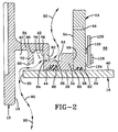
- the invention achieves its desirable water-protection capability by allowing air to readily enter and exit the mechanical compartment 68 of the enclosure 10. The manner that this is done is better appreciated with reference to Figure 2, which is a sectional view along the lines 2-2 of the fully assembled enclosure 10 shown in Figure 1.
- the first channel 40 in the faceplate 12 is defined at one end by the attachment wall 18, and at the other end by an opposed, axially spaced apart first shoulder 72 that extends radially outwardly from the cylindrical wall 34 of the faceplate 12.
- the second channel 42 is defined by the first shoulder 72 and an opposed, axially spaced apart second shoulder 74 that extends radially outwardly from the cylindrical wall 34.
- the first shoulder 72 is axially intermediate the attachment wall 18 and the second shoulder 74.
- a slot 76 extends in the circumferential direction through the second shoulder 74 and provides fluid communication between the mechanical compartment 68 and the ambient atmosphere external to the enclosure 10. Accordingly, air freely passes into and out of the mechanical compartment 68.
- the circumferential length of the slot 76 is greater than its radial width to allow liquid condensate to drain easily from the mechanical compartment 68; slot widths in the range of about 0.5 - 6.7 inches have been useful, with lengths somewhat greater, to allow water and other liquids to drain from the enclosure interior at a variety of aircraft attitude conditions.
- the axially extending centerline 78 of the slot 76 is radially inward of the outer end 80 of the first shoulder 72.
- the inner and outer surfaces 82 and 84, respectively, of the slot 76 are both inward of the shoulder end 80.
- the slot surface 82 is outwardly spaced from the portion 85 of the cylindrical wall 34 that lies between first and second shoulders 72 and 74.
- the cover 16 When fully assembled, the cover 16 is engaged against the outer surface 38 of the faceplate 12 by the o-ring seal 86 in the groove 44. Additionally, the cover 16 is sealingly engaged against the rim 62 of the bulkhead 14 by the o-ring seal 88 in the groove 60.
- the use of o-rings is not critical to the invention; other types of sealing means will be useful, as is well known to those with ordinary skill in the art.
- the axial end 90 of the cover 16 is adjacent to the attachment wall 18 of the faceplate 12, and is between the wall 18 and the first shoulder 72. Because the cover end 90 does not extend all the way to the attachment wall 18, air may readily flow between the wall 18 and cover end 90, past the first shoulder 72, through the slot 76, and into and out of the mechanical compartment 68, as indicated by the arrows 92.
- the outer surface 84 of the slot 76 is defined by the water collection surface 52.
- the condensate will, by the force of gravity, collect on the water collection surface 52, and flow through the slot 76 and out of the enclosure 10.
- fluid spray e.g., rain, water washings, etc.
- the liquid will also simply drain out of the slot 76 under the influence of gravitational forces.
- four slots 76 are spaced about a semicircular sector of the faceplate 12. When the enclosure 10 is installed on an airplane, the circumferential midpoint of one slot 76 is substantially aligned with the vertical direction when the airplane is at rest on the ground.
- the slot 76 through the second shoulder 74 therefore performs a dual role: allowing air to freely pass in and out of the mechanical compartment 68, and allowing any liquid, typically in the form of condensate, to easily drain from such compartment.
- This construction is contrasted with prior art designs, where air is excluded from the compartment by a hermetic seal; however once the seal breaks in these prior art designs, and air is able to leak into the compartment, it is trapped there by the still functioning (albeit not perfectly functioning) seal. If the trapped air contains any moisture, as it likely will, that trapped moisture will eventually cause any metal components in the prior an enclosure compartment to corrode.
- components in the mechanical compartment 68 are physically isolated, by the bulkhead 14, from the components in the electronic compartment 66.
- the bulkhead 14 therefore keeps moisture in the mechanical compartment from passing into the electronic compartment. Any moisture that does, however, enter the electronic compartment 66 is evaporated by heater 126 attached to heat sink 124.
- the heat sink 124 is arc shaped and is attached to a stand-off 122 on the electronics side of, the bulkhead 14, so that the heat sink 120 is separated from the bulkhead 14 by a slight air gap 123.
- the air gap 124 thermally insulates the heat sink 120 from the bulkhead 14.
- a low wattage heater 126 which draws from the same voltage source (not shown) that powers the electronic components within the enclosure, is thermally coupled to the heat sink 124.
- the heater 126 constantly draws power and raises the temperature of the heat sink 120.
- the heat sink 120 radiates heat into the space within the electronics compartment 66, limiting the condensation of humid air that may find its way into the electronics compartment 66; the heat also vaporizes any moisture that does condense in the electronics compartment 66, which keeps the electronics compartment 66 dry and corrosion free.
- the bulkhead 14 may include a vent hole 94 that allows air to pass between the electronics compartment 66 and the mechanical compartment 68; any humid air in the electronics compartment 66 when the aircraft is on the ground will likely be drawn out of such compartment, through the vent hole 94, as the aircraft takes flight into higher altitudes and lower pressures.
- the vent hole 94 assists the electronics compartment 66 in cleansing itself of humid air.
- a flap position transmitter for an aircraft such as a modern, turbine engine powered airplane.
- a flap position transmitter of this sort informs the pilot of the aerodynamic position of the wing flaps, so that they may be adjusted as necessary, during flight.
- the flap position transmitter includes a rotating shaft that is attached by appropriate linkages to the underside surface of the flap; movement of the flap is either the up or down direction causes the shaft to rotate. Such rotation is then converted, through conventional electronic processing, into a signal indicative of the flap's position that is sent to the pilot in the cockpit.
- the shaft 96 of the transmitter 100 extends in the axial direction from the enclosure 10; a first end 102 of the shaft 96 is secured to a flap linkage 104. A second end 106 of the shaft 96 is attached to a main gear 108 that is one of the mechanical components secured within the enclosure 10.
- the main gear 108 drives additional gears coupled to transducers that convert the rotary motion of the gear to an output voltage signal in the typical fashion; the output voltage is proportional to the amount of rotation of the gear.
- the main gear 108 drives a pinion gear 110 coupled by shaft 112 to a linear transformer 114.
- the main gear 108 drives another pinion gear (not shown) coupled by shaft 116 to a synchronization transmitter 118.
- pinion gears may also be driven by the main gear 108, depending on the particular function to be performed by the position transmitter.
- the output voltage from the linear transformer 114 is transmitted to the pin connector 70 and then to a computer in the cockpit. This signal informs the pilot of the position of the wing flaps.
- the signal may also be processed by appropriate electronic circuitry (not shown) within the electronics compartment 66 and sent to relays that are programmed to, e.g., turn on or off warning lights such as the "Fasten Seat Belt” light in the passenger portion of the airplane.
- the synchronization transmitter performs a similar function as the linear transformer, but instead provides a signal to, e.g., a flight control computer that controls other functions of the airplane that are affected by the position of the control surface.
- the enclosure of this invention is not limited to application as a flap position transmitter.
- the particular mechanical and electronic components housed therein are not critical aspects of the invention.
- the enclosure will find numerous uses in operating environments where the components must be kept free of moisture that will invariable and eventually cause corrosion and failure.
- the enclosure of this invention achieves such desirable characteristics by its use of a cylindrically-shaped faceplate with a plurality of grooves extending about its outer diameter that allow the enclosure to efficiently shed water that collects on the enclosure outer surface; and at least one labyrinth passageway that is constructed and arranged to allow air to freely circulate through the enclosure's mechanical compartment and thereby continually cleanse the compartment of humid air that might otherwise stagnate and condense.
- the construction of the faceplate and preferred orientation of the enclosure when attached to the aircraft causes the condensate to collect on the water collection surface and flow through the slot and out of the mechanical compartment.
- the low wattage heater in the electronics compartment keeps the electronics dry and corrosion free.
Landscapes
- Physics & Mathematics (AREA)
- General Physics & Mathematics (AREA)
- Casings For Electric Apparatus (AREA)
- Transmitters (AREA)
- Details Of Aerials (AREA)
Applications Claiming Priority (2)
| Application Number | Priority Date | Filing Date | Title |
|---|---|---|---|
| US08/926,815 US6098474A (en) | 1997-09-09 | 1997-09-09 | Enclosure for position transmitter |
| US926815 | 1997-09-09 |
Publications (2)
| Publication Number | Publication Date |
|---|---|
| EP0902259A2 true EP0902259A2 (de) | 1999-03-17 |
| EP0902259A3 EP0902259A3 (de) | 2002-05-22 |
Family
ID=25453759
Family Applications (1)
| Application Number | Title | Priority Date | Filing Date |
|---|---|---|---|
| EP19980116751 Withdrawn EP0902259A3 (de) | 1997-09-09 | 1998-09-04 | Gehäuse für Positionsgeber |
Country Status (2)
| Country | Link |
|---|---|
| US (1) | US6098474A (de) |
| EP (1) | EP0902259A3 (de) |
Cited By (1)
| Publication number | Priority date | Publication date | Assignee | Title |
|---|---|---|---|---|
| EP2347314A4 (de) * | 2008-10-16 | 2013-05-01 | Rosemount Inc | Feldvorrichtung mit integrierter temperatursteuerung |
Families Citing this family (1)
| Publication number | Priority date | Publication date | Assignee | Title |
|---|---|---|---|---|
| JP3570329B2 (ja) * | 2000-02-29 | 2004-09-29 | 日本電気株式会社 | 圧力調整機能付密閉筐体 |
Family Cites Families (15)
| Publication number | Priority date | Publication date | Assignee | Title |
|---|---|---|---|---|
| US4275593A (en) * | 1979-04-06 | 1981-06-30 | Thornton Trump Walter E | Specific gravity meter for aircraft de-icing equipment |
| US4336721A (en) * | 1980-06-03 | 1982-06-29 | Hague International | Gas analyzer |
| US4378697A (en) * | 1981-07-06 | 1983-04-05 | Rosemount Inc. | Strut mounted multiple static tube |
| US4549706A (en) * | 1983-06-01 | 1985-10-29 | Rosemount Inc. | Flow data sensor duct system |
| US4730487A (en) * | 1985-06-04 | 1988-03-15 | Rosemount Inc. | Family of aerodynamically compensated multiple static pressure tubes |
| GB2203251B (en) * | 1987-03-25 | 1991-08-07 | Rosemount Ltd | Air data measurement apparatus |
| US5046360A (en) * | 1989-12-15 | 1991-09-10 | Rosemount Inc. | Aerodynamic probe internal constructions |
| US5178022A (en) * | 1991-08-27 | 1993-01-12 | Tomlin Robert L | Inertial filtration external dilution probe |
| DE4142727B4 (de) * | 1991-12-21 | 2004-09-30 | Valeo Schalter Und Sensoren Gmbh | Drehzahlsensor |
| US5458008A (en) * | 1993-12-10 | 1995-10-17 | The B.F. Goodrich Company | Condensation and evaporation system for air data sensor system |
| US5433865A (en) * | 1994-03-31 | 1995-07-18 | Laurent; Edward L. | Method for treating process waste streams by use of natural flocculants |
| US5571960A (en) * | 1994-04-08 | 1996-11-05 | Aisan Kogyo Kabushiki Kaisha | Throttle valve opening degree sensor |
| US5546804A (en) * | 1994-08-11 | 1996-08-20 | Rosemount Inc. | Transmitter with moisture draining housing and improved method of mounting RFI filters |
| US5601254A (en) * | 1994-10-28 | 1997-02-11 | Rosemount Aerospace Inc. | Single sided backbone strut for air data sensor |
| US5583287A (en) * | 1994-11-25 | 1996-12-10 | Chrysler Corporation | Drainage and pressure relief vent for a sensor |
-
1997
- 1997-09-09 US US08/926,815 patent/US6098474A/en not_active Expired - Lifetime
-
1998
- 1998-09-04 EP EP19980116751 patent/EP0902259A3/de not_active Withdrawn
Cited By (1)
| Publication number | Priority date | Publication date | Assignee | Title |
|---|---|---|---|---|
| EP2347314A4 (de) * | 2008-10-16 | 2013-05-01 | Rosemount Inc | Feldvorrichtung mit integrierter temperatursteuerung |
Also Published As
| Publication number | Publication date |
|---|---|
| US6098474A (en) | 2000-08-08 |
| EP0902259A3 (de) | 2002-05-22 |
Similar Documents
| Publication | Publication Date | Title |
|---|---|---|
| JP2005514258A (ja) | 同一面埋込表面大気データセンサ | |
| PT87192B (pt) | Classificador centrifugo | |
| EP3462179B1 (de) | Integrierter schaufelbasis-anstellwinkelsensor | |
| US6098474A (en) | Enclosure for position transmitter | |
| KR100303971B1 (ko) | 압축기용 오일 수준 관측창 | |
| CN108930824A (zh) | 排放阀、外部飞行器灯单元和电源箱 | |
| US20050089082A1 (en) | Sensor arrangement having an air inflow pattern for preventing direct debris impact | |
| KR860009520A (ko) | 교류 발전기 | |
| EP1734385B1 (de) | Rückstrahlanordnung und Opazitätsbildschirm damit | |
| US20190092621A1 (en) | Board mounted microelectromechanic system (mems) sensors for motor diagnostics and analytics | |
| CN108709728B (zh) | 离心通风器性能试验装置 | |
| US3534600A (en) | Aircraft measuring device | |
| US12386040B2 (en) | Rotatable sensor assembly with elastomeric flap | |
| Pearson Jr | Measuring ambient ozone with high sensitivity and bandwidth | |
| CA3005534C (en) | Static pressure tap | |
| US20240201333A1 (en) | Sensor assembly | |
| WO2015090388A1 (en) | Housing for a sensor-bearing unit, sensor-bearing unit comprising such housing and apparatus comprising such unit | |
| US6877966B2 (en) | Apparatus for indicating remaining life expectancy of a rotary sliding vane pump | |
| EP2907756B1 (de) | Vorrichtung zur Erfassung einer oder mehrerer Eigenschaften einer Flüssigkeit | |
| US20180281513A1 (en) | Wheel end sensor mounting assembly for heavy-duty vehicles | |
| US9580187B2 (en) | Rotor index sensor system | |
| EP3754342B1 (de) | Anstellwinkelsensor | |
| US2845141A (en) | Accessory oiling system | |
| JPH0227224A (ja) | 極低温容器及びこれを用いた光測定器 | |
| JP2726342B2 (ja) | エンジンオイル劣化検出装置 |
Legal Events
| Date | Code | Title | Description |
|---|---|---|---|
| PUAI | Public reference made under article 153(3) epc to a published international application that has entered the european phase |
Free format text: ORIGINAL CODE: 0009012 |
|
| AK | Designated contracting states |
Kind code of ref document: A2 Designated state(s): AT BE CH CY DE DK ES FI FR GB GR IE IT LI LU MC NL PT SE |
|
| AX | Request for extension of the european patent |
Free format text: AL;LT;LV;MK;RO;SI |
|
| PUAL | Search report despatched |
Free format text: ORIGINAL CODE: 0009013 |
|
| AX | Request for extension of the european patent |
Free format text: AL;LT;LV;MK;RO;SI |
|
| AKX | Designation fees paid | ||
| REG | Reference to a national code |
Ref country code: DE Ref legal event code: 8566 |
|
| STAA | Information on the status of an ep patent application or granted ep patent |
Free format text: STATUS: THE APPLICATION IS DEEMED TO BE WITHDRAWN |
|
| 18D | Application deemed to be withdrawn |
Effective date: 20021123 |