EP0902236A2 - Bougie à incandescence - Google Patents
Bougie à incandescence Download PDFInfo
- Publication number
- EP0902236A2 EP0902236A2 EP98117067A EP98117067A EP0902236A2 EP 0902236 A2 EP0902236 A2 EP 0902236A2 EP 98117067 A EP98117067 A EP 98117067A EP 98117067 A EP98117067 A EP 98117067A EP 0902236 A2 EP0902236 A2 EP 0902236A2
- Authority
- EP
- European Patent Office
- Prior art keywords
- diameter portion
- glow plug
- small
- heating coil
- coil
- Prior art date
- Legal status (The legal status is an assumption and is not a legal conclusion. Google has not performed a legal analysis and makes no representation as to the accuracy of the status listed.)
- Granted
Links
Images


Classifications
-
- F—MECHANICAL ENGINEERING; LIGHTING; HEATING; WEAPONS; BLASTING
- F23—COMBUSTION APPARATUS; COMBUSTION PROCESSES
- F23Q—IGNITION; EXTINGUISHING-DEVICES
- F23Q7/00—Incandescent ignition; Igniters using electrically-produced heat, e.g. lighters for cigarettes; Electrically-heated glowing plugs
- F23Q7/001—Glowing plugs for internal-combustion engines
Definitions
- the present invention relates generally to a glow plug designed to preheat a combustion chamber of a diesel engine for ensuring quick starting, and more particularly to an improved structure of a glow plug which avoids the overheat of a heating element of the glow plug to prolong the service life thereof.
- Glow plugs are used as a preheating element serving to heat a diesel engine above a self-starting temperature during a starting mode of engine operation.
- self-temperature controlled glow plugs using a coil made of two different materials.
- This type of glow plug includes a heating coil and a current-controlling coil connected electrically to the heating coil in series.
- the current-controlling coil is made of material having a positive temperature coefficient of resistance greater than that of the heating coil and serves to avoid the overheat of the heating coil for improving the durability thereof.
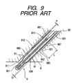
- Figs. 8 and 9 show a conventional glow plug 9.
- the glow plug 9 is, as shown in Fig. 9, mounted in a glow plug mount hole 81 in engagement with threads 811.
- the glow plug 9 includes a heater casing 91 having disposed therein a heating element 90 and a housing 92 within which the heater casing 91 is partially installed.
- the heater casing 91 projects from the housing 92 and includes a head portion 911 having an outer diameter d smaller than an inner diameter of the housing 92 and a major portion 912 having an outer diameter D greater than the outer diameter d.
- the heating element 90 includes a heating coil 901 and a current-controlling coil 902.
- the heating coil 901 is disposed within the head portion 911 of the heater casing 91, while the current-controlling coil 902 is disposed within the major portion 912.
- a clearance 985 (also indicated by Q) is, as shown in Fig. 9, formed between the engine head 8 and the heater casing 91.
- a pocket 987 is formed between the housing 92 and the heater casing 91 with a clearance P by machining an inner wall of a head portion 921 of the housing 92 for facilitating assembly of the glow plug 9.
- the heating element 90 is connected to an outer terminal 932 through a central shaft 931.
- the outer terminal 932 is connected to a power supply (not shown).
- a base portion 922 of the housing 92 is hexagonal and retains the central shaft 931 and the outer terminal 932 through an insulating bush 951 and a metallic nut 952.
- the reference number 938 employed in Figs. 8 and 9 denotes a magnesia powder for electrical insulation.
- the outer diameter d of the head portion 911 is ⁇ 4.3 mm.
- the outer diameter D of the major portion 912 is ⁇ 5.0 mm.
- the diameter of the glow plug mount hole 81 is ⁇ 5.5 mm.
- the clearance 985 is 0.25 mm.
- the inner diameter of the pocket 987 is ⁇ 5.3 mm.
- the clearance P is 0.15 mm.
- the temperature of the current-controlling coil 902 After energized, the temperature of the current-controlling coil 902 must be elevated quickly up to a set value within a given period of time.
- the clearance 985 between the major portion 912 of the heater casing 91 and the inner wall of the glow plug mount hole 91 is relatively small, so that the heat of the current-controlling coil 902 will be transferred easily to the engine head 8, thereby causing the temperature rise of the current-controlling coil 902 up to the set value to be delayed, precluding a quick rise in resistance of the current-controlling coil 902 or decrease in current flowing through the current-controlling coil 902. This results in overheat of the heating coil 901, thereby shortening the service life of the glow plug 9.
- the heat of the current-controlling coil 902 is also transferred to the engine head 8 through the major portion 912 and the housing 92, thereby promoting the overheat of the heating coil 901 and the decrease in service lift of the glow plug 9.
- the coefficient of heat transmission of gas is smaller than that of solid.
- the clearance 985 when the clearance 985 is filled with air, it will reduce the heat transfer to the engine head 8.
- carbon whose coefficient of heat transmission is greater than that of air and which is produced by combustion of fuel and oil, however, chokes the clearance 985 and the pocket 987, thereby further promoting the overheat of the heating coil 901.
- the above problems may be alleviated by increasing the diameter of the glow plug mount hole 81 to increase the clearance 985 between the glow plug mount hole 81 and the heater casing 91 to suppress the heat transfer to the engine head 8. This may, however, cause the mechanical strength of the engine head 8 to be decreased.
- the diameter of the glow plug mount hole 81 be as small as possible for the improvement of the mechanical strength or durability of the engine.
- a glow plug which comprises: (a) a hollow housing of a given length having an open end; (b) a heating coil; (c) a current-controlling coil having a positive temperature coefficient of resistance greater than that of the heating coil, connected to an end of the heating coil; and (d) a heater casing, having disposed therein the heating coil and the current-controlling coil, inserted partially into the housing from the open end.
- the heater casing includes a small-diameter portion and a large-diameter portion connected in series with the small-diameter portion. The whole of the large-diameter portion is disposed within the housing in engagement therewith. The whole of the small-diameter portion projects from the open end of the housing.
- the heating coil and the current-controlling coil are disposed only within the small-diameter portion of the heater casing.
- the heater casing further includes a tapered portion connecting the small-diameter portion and the large-diameter portion.
- the heating coil and the current-controlling coil are disposed only within a portion of the heater casing ranging from a junction of the tapered portion and the large diameter portion to the small-diameter portion.
- a glow plug mount structure which comprises a glow plug and a glow plug mount hole.
- the glow plug includes (a) a hollow housing of a given length having an open end, (b) a heating coil, (c) a current-controlling coil having a positive temperature coefficient of resistance greater than that of the heating coil, connected to an end of the heating coil, and (d) a heater casing, having disposed therein the heating coil and the current-controlling coil, inserted partially into the housing from the open end.
- the heater casing includes a small-diameter portion and a large-diameter portion connected in series with the small-diameter portion.
- the whole of the large-diameter portion is disposed within the housing in engagement therewith, while the whole of the small-diameter portion projects from the open end of the housing.
- the glow plug mount hole is formed in an engine and has mounted therein the glow plug with a clearance of 0.25 mm or more between an outer wall of the small-diameter portion of the heater casing of the glow plug and an inner wall of the glow plug mount hole.
- the heating coil and the current-controlling coil are disposed only within the small-diameter portion of the heater casing.
- the heater casing further includes a tapered portion connecting the small-diameter portion and the large-diameter portion.
- the heating coil and the current-controlling coil are disposed only within a portion of the heater casing ranging from a junction of the tapered portion and the large diameter portion to the small-diameter portion.
- a glow plug 1 according to the first embodiment of the present invention.
- the glow plug 1 includes generally a heating coil 21, a current-controlling coil 22, a cylindrical heater casing 3 having disposed therein the coils 21 and 22, and a cylindrical hollow housing 5 retaining therein a base end 39 of the heater casing 3.
- the heater casing 3 consists of a large-diameter portion 32 continuing the base end 39, a small-diameter portion 31, and a tapered portion 33.
- the small-diameter portion 31 has the diameter d smaller than the diameter D of the large-diameter portion 32.
- the large-diameter portion 32 is press-fitted into the housing 5.
- the small-diameter portion 31 extends outside from an open end 51 of the housing 5 and has a closed head 36.
- the tapered portion connects the large-diameter portion 32 and the small-diameter portion 31 and decreases in diameter toward the small-diameter portion gradually for avoiding the concentration of stress at the junction of the large-diameter portion 32 and the small-diameter portion 31.
- the heater casing 3 may alternatively be brazed to the housing 5.
- the tapered portion 33 is shaped by a drawing die when forming the small-diameter portion 31 by drawing such as swaging.
- the current-controlling coil 22 is made of material having a positive temperature coefficient of resistance greater than that of the heating coil 21 and connects with an end 29 of the heating coil 21 to control the current flowing to the heating coil 21.
- the current-controlling coil 22 is disposed only within the small-diameter portion 31 of the heater casing 3 together with the heating coil 21.
- the heating coil 21 is disposed within the small-diameter portion 31 of the heater casing 3 on the side of the head 36, while the current-controlling coil 22 is disposed on the side of the base end 39.
- the temperature coefficient of resistance of the heating coil 21 may be either positive or negative.
- the glow plug 9 is, as clearly shown in Fig. 2, mounted in a glow plug mount hole 81 formed in an engine head 8 with a clearance of 0.6 mm between an outer wall of the small-diameter potion 31 of the heater casing 3 and an inner wall of the glow plug mount hole 81.
- the heater casing 3 is filled with a magnesia powder 38 around the heating coil 21, the current-controlling coil 22, and the central shaft 61 for electrical insulation.
- a power supply terminal 62 is connected to the current-controlling coil 22 through the central shaft 61 and installed in a hexagonal base 52 of the housing 5 together with the central shaft 61 through an insulating bush 71 and a metallic nut 72.
- the outer diameter d of the small-diameter portion 31 is ⁇ 4.3 mm.
- the outer diameter D of the large-diameter portion 32 is ⁇ 5.0 mm.
- the diameter of the glow plug mount hole 81 is ⁇ 5.5 mm.
- the clearance 85 is 0.6 mm.
- the inner diameter of the housing 5 is ⁇ 5.0 mm.
- the large-diameter portion 32 of the heater casing 3 is, as described above, disposed within the housing 5 without projecting from the open end 51. Therefore, when the diameter of the glow plug mount hole 81 is ⁇ 5.5 mm equal to that of the conventional structure shown in Fig. 9, it will produce, as shown in Fig. 2, a greater clearance Q of 0.6 mm between the heater casing 3 and the inner wall of the glow plug mount hole 81, thereby reducing the heat transfer from the current-controlling coil 22 to the engine head 8.
- the heating coil 21 and the current-controlling coil 22 are disposed only within the small-diameter portion 31 of the heater casing 3 which is located on the side of the head 36 from a boundary B of the large-diameter portion 32 and the tapered portion 33 and which extends outside the housing 5. Thus, even if the clearance between the housing 5 and the tapered portion 33 of the heater casing 3 is, as shown in Fig. 2, choked with carbon 89, the heat of the current-controlling coil 22 is hardly transferred to the engine-head 8 through the housing 5.
- the structure of the glow plug 1 avoids the heat transfer from the current-controlling coil 22 to the outside through the housing 5 as well as the clearance 85.
- the reduction in heat transfer to the outside facilitates rise in temperature of the current-controlling coil 22 up to a set value within a given period of time following energization of the current-controlling coil 22. This enables accurate control of increase in resistance of the current-controlling coil 22 or decrease in current flowing therethrough, thereby avoiding the overheat of the heating coil 21.
- the clearance Q between the heater casing 3 and the glow plug mount hole 81 is 0.25 mm equal to that in the conventional structure shown in Fig. 9, it will allow the diameter of the glow plug mount hole 81 to be decreased to ⁇ 4.8 mm, thereby increasing the mechanical strength of the engine head 8 which will result in greatly improved durability of the engine. This also allows air inlet and outlet ports of the engine to be increased in diameter for enhancing the engine output.
- a temperature rise of the heating coil 21 was measured for different values of the clearance 85 between the inner wall of the glow plug mount hole 81 of the engine head 8 and the small-diameter portion 31 of the heater casing 3 when the clearance 85 is choked with carbon.
- the measurement of temperature of the heating coil 21 was made forty seconds after a rated voltage of 11V was applied to the glow plug 1 mounted in an engine after operating for 100 hours at 2000 rpm under full load conditions. The results are shown in Fig. 3.
- the temperature of the heating coil 21 is elevated rapidly as the clearance 85 is decreased.
- the clearance 85 is less than 0.25 mm, the temperature of the heating coil 21 exceeds 100°C, which will cause the service life of the glow plug 1 to be shortened greatly. It is, thus, advisable that the clearance 85 be greater than 0.25 mm or more.
- the outer diameter d of the small-diameter portion 31 of the heater casing 3 be ⁇ 2.5 mm to ⁇ 4.8 mm. In this case, decreasing the outer diameter d of the small-diameter portion 31 allows the clearance 85 to be increased or the glow plug mount hole 81 to be decreased in diameter.
- the outer diameter d of the small-diameter portion 31 is less than ⁇ 2.5 mm, the difficulty is encountered in machining the small-diameter portion 31. Conversely, if the outer diameter d of the small-diameter portion 31 is more than ⁇ 4.8 mm, the above described advantages of the invention are not obtained.
- Figs. 4 and 5 show a glow plug 4 according to the second embodiment of the invention.
- the glow plug 4 has the current-controlling coil 22 disposed partially inside the open end 921 of the housing 92.
- the central shaft 61 is, thus, shorter than that of the first embodiment by the distance L corresponding to a length of the current-controlling coil 22 disposed within the housing 92, thereby forming the pocket 87 between the housing 92 and the small-diameter portion 31 of the heater casing 3.
- the pocket 87 has an inner diameter of ⁇ 5.3 mm and defines a clearance P of 0.5 mm between the small-diameter portion 31 and the inner wall of the housing 92 which is greater than the clearance P of 0.15 mm in the conventional structure shown in Fig. 9. This reduces the heat transfer from the current-controlling coil 22 to the engine head 8 through the pocket 87 even when the pocket 87 is choked with carbon.
- a temperature rise of the heating coil 21 was measured for different values of the length L of the current-controlling coil 22 disposed within the housing 92 when the pocket 87 is choked with carbon.
- the measurement of temperature of the heating coil 21 was made forty seconds after a rated voltage of 11V was applied to the glow plug 1 removed from an engine after operating for 100 hours at 2000 rpm under full load conditions without influence of carbon in the clearance 85.
- the results are shown in Fig. 6.
- a broken line indicates as a comparative example a temperature rise of the heating coil 22 in the conventional structure, as shown in Figs. 8 and 9, wherein the pocket 987 or clearance P is 0.15.
- the temperature of the heating coil 21 is elevated greatly as the length L is increased. If the length L in this embodiment is identical with that in the comparative example, the temperature rise of the heating coil 21 of this embodiment is found to be lower than that of the comparative example.
- Fig. 7 shows a glow plug 11 according to the third embodiment of the invention which is different from the first embodiment only in that the rear end 228 of the current-controlling coil 22 leading to the tip of the central shaft 61 is arranged within the tapered portion 33 of the heater casing 3.
- Other arrangements are identical with those of the first embodiment, and explanation thereof in detail will be omitted here.
- the connecting portion 229 of the current-controlling coil 22 wrapped about the tip of the central shaft 61 is, as shown in Fig. 7, disposed within the tapered portion 33, but may alternatively be arranged on the side of the large-diameter portion 32 from the boundary B of the large-diameter portion 32 and the tapered portion 32 because the connecting portion 229 does not provide the current control as compared with the other portion of the current-controlling coil 22.
- a glow plug used in diesel engines which includes a plug housing, a heater casing, and a heating element.
- the heating element consists of a heating coil and a current-controlling coil connected in series with the heating coil to control the current flowing to the heating coil.
- the heater casing has disposed therein the heating coil and the current-controlling coil and is inserted partially into the housing from an open end thereof.
- the heater casing includes a small-diameter portion and a large-diameter portion connected in series with the small-diameter portion.
- the whole of the large-diameter portion is disposed within the housing in tight engagement therewith, while the whole of the small-diameter portion projects from the open end of the housing for producing a clearance with an inner wall of a glow plug mount hole formed in an engine head to minimize the heat transfer from the heating element to the engine head.
Landscapes
- Engineering & Computer Science (AREA)
- Chemical & Material Sciences (AREA)
- Combustion & Propulsion (AREA)
- Mechanical Engineering (AREA)
- General Engineering & Computer Science (AREA)
- Resistance Heating (AREA)
Applications Claiming Priority (6)
| Application Number | Priority Date | Filing Date | Title |
|---|---|---|---|
| JP26791797 | 1997-09-11 | ||
| JP267917/97 | 1997-09-11 | ||
| JP26791797 | 1997-09-11 | ||
| JP233362/98 | 1998-08-20 | ||
| JP23336298 | 1998-08-20 | ||
| JP23336298A JP3551032B2 (ja) | 1997-09-11 | 1998-08-20 | グロープラグ |
Publications (3)
| Publication Number | Publication Date |
|---|---|
| EP0902236A2 true EP0902236A2 (fr) | 1999-03-17 |
| EP0902236A3 EP0902236A3 (fr) | 2000-10-11 |
| EP0902236B1 EP0902236B1 (fr) | 2005-04-13 |
Family
ID=26531010
Family Applications (1)
| Application Number | Title | Priority Date | Filing Date |
|---|---|---|---|
| EP19980117067 Revoked EP0902236B1 (fr) | 1997-09-11 | 1998-09-09 | Bougie à incandescence |
Country Status (4)
| Country | Link |
|---|---|
| EP (1) | EP0902236B1 (fr) |
| JP (1) | JP3551032B2 (fr) |
| DE (1) | DE69829715T2 (fr) |
| ES (1) | ES2242256T3 (fr) |
Family Cites Families (1)
| Publication number | Priority date | Publication date | Assignee | Title |
|---|---|---|---|---|
| JP2745225B2 (ja) * | 1989-02-15 | 1998-04-28 | 自動車機器株式会社 | デイーゼルエンジン用グロープラグ |
-
1998
- 1998-08-20 JP JP23336298A patent/JP3551032B2/ja not_active Expired - Lifetime
- 1998-09-09 ES ES98117067T patent/ES2242256T3/es not_active Expired - Lifetime
- 1998-09-09 DE DE69829715T patent/DE69829715T2/de not_active Revoked
- 1998-09-09 EP EP19980117067 patent/EP0902236B1/fr not_active Revoked
Also Published As
| Publication number | Publication date |
|---|---|
| DE69829715D1 (de) | 2005-05-19 |
| EP0902236B1 (fr) | 2005-04-13 |
| DE69829715T2 (de) | 2006-04-27 |
| ES2242256T3 (es) | 2005-11-01 |
| EP0902236A3 (fr) | 2000-10-11 |
| JPH11148647A (ja) | 1999-06-02 |
| JP3551032B2 (ja) | 2004-08-04 |
Similar Documents
| Publication | Publication Date | Title |
|---|---|---|
| US6037568A (en) | Glow plug for diesel engine with ptc control element disposed in small-diameter sheath section and connected to the distal end thereof | |
| US4725711A (en) | Self temperature control type glow plug | |
| US6396028B1 (en) | Multi-layer ceramic heater | |
| PL190854B1 (pl) | Grzałka ceramiczna | |
| US2130365A (en) | Igniter for internal combustion engines | |
| US4682008A (en) | Self-temperature control type glow plug | |
| US6878903B2 (en) | Glow plug | |
| US5319180A (en) | Glow plug with constant-structure cobalt-iron PTC resistor | |
| JPH11257659A (ja) | セラミックヒータ及びセラミックグロープラグ | |
| US4650963A (en) | Ceramic glow plug | |
| US5251589A (en) | Hot tip glow plug and method for making | |
| EP0648978A2 (fr) | Bougie à incandescence en céramique | |
| US20080149613A1 (en) | Glow plug for internal combustion engine | |
| EP0902236B1 (fr) | Bougie à incandescence | |
| JP2004061041A (ja) | セラミックグロープラグ | |
| JP3560753B2 (ja) | ディーゼルエンジン用グロープラグ | |
| JPH11294769A (ja) | グロープラグ | |
| JP3536261B2 (ja) | グロープラグ | |
| EP1102007B1 (fr) | Bougie à incandescence | |
| JP2000130752A (ja) | グロープラグ | |
| EP0240650A1 (fr) | Bougie à incandescence à deux enroulements chauffants pour des moteurs Diesel | |
| JP2001524655A (ja) | 内燃機関のためのシース形グロープラグ | |
| JPH0311576Y2 (fr) | ||
| JPH0155370B2 (fr) | ||
| JPH0233015Y2 (fr) |
Legal Events
| Date | Code | Title | Description |
|---|---|---|---|
| PUAI | Public reference made under article 153(3) epc to a published international application that has entered the european phase |
Free format text: ORIGINAL CODE: 0009012 |
|
| AK | Designated contracting states |
Kind code of ref document: A2 Designated state(s): DE ES FR GB |
|
| AX | Request for extension of the european patent |
Free format text: AL;LT;LV;MK;RO;SI |
|
| PUAL | Search report despatched |
Free format text: ORIGINAL CODE: 0009013 |
|
| AK | Designated contracting states |
Kind code of ref document: A3 Designated state(s): AT BE CH CY DE DK ES FI FR GB GR IE IT LI LU MC NL PT SE |
|
| AX | Request for extension of the european patent |
Free format text: AL;LT;LV;MK;RO;SI |
|
| 17P | Request for examination filed |
Effective date: 20001123 |
|
| AKX | Designation fees paid |
Free format text: DE ES FR GB |
|
| 17Q | First examination report despatched |
Effective date: 20021114 |
|
| GRAP | Despatch of communication of intention to grant a patent |
Free format text: ORIGINAL CODE: EPIDOSNIGR1 |
|
| GRAS | Grant fee paid |
Free format text: ORIGINAL CODE: EPIDOSNIGR3 |
|
| GRAA | (expected) grant |
Free format text: ORIGINAL CODE: 0009210 |
|
| AK | Designated contracting states |
Kind code of ref document: B1 Designated state(s): DE ES FR GB |
|
| REG | Reference to a national code |
Ref country code: GB Ref legal event code: FG4D |
|
| REF | Corresponds to: |
Ref document number: 69829715 Country of ref document: DE Date of ref document: 20050519 Kind code of ref document: P |
|
| REG | Reference to a national code |
Ref country code: ES Ref legal event code: FG2A Ref document number: 2242256 Country of ref document: ES Kind code of ref document: T3 |
|
| PLBI | Opposition filed |
Free format text: ORIGINAL CODE: 0009260 |
|
| ET | Fr: translation filed | ||
| PLAX | Notice of opposition and request to file observation + time limit sent |
Free format text: ORIGINAL CODE: EPIDOSNOBS2 |
|
| 26 | Opposition filed |
Opponent name: BERU AG Effective date: 20060113 |
|
| PLBB | Reply of patent proprietor to notice(s) of opposition received |
Free format text: ORIGINAL CODE: EPIDOSNOBS3 |
|
| APBP | Date of receipt of notice of appeal recorded |
Free format text: ORIGINAL CODE: EPIDOSNNOA2O |
|
| APAH | Appeal reference modified |
Free format text: ORIGINAL CODE: EPIDOSCREFNO |
|
| APBP | Date of receipt of notice of appeal recorded |
Free format text: ORIGINAL CODE: EPIDOSNNOA2O |
|
| APBQ | Date of receipt of statement of grounds of appeal recorded |
Free format text: ORIGINAL CODE: EPIDOSNNOA3O |
|
| APBQ | Date of receipt of statement of grounds of appeal recorded |
Free format text: ORIGINAL CODE: EPIDOSNNOA3O |
|
| PGFP | Annual fee paid to national office [announced via postgrant information from national office to epo] |
Ref country code: GB Payment date: 20090909 Year of fee payment: 12 |
|
| APBU | Appeal procedure closed |
Free format text: ORIGINAL CODE: EPIDOSNNOA9O |
|
| PGFP | Annual fee paid to national office [announced via postgrant information from national office to epo] |
Ref country code: ES Payment date: 20091006 Year of fee payment: 12 Ref country code: DE Payment date: 20090903 Year of fee payment: 12 |
|
| RDAF | Communication despatched that patent is revoked |
Free format text: ORIGINAL CODE: EPIDOSNREV1 |
|
| RDAG | Patent revoked |
Free format text: ORIGINAL CODE: 0009271 |
|
| STAA | Information on the status of an ep patent application or granted ep patent |
Free format text: STATUS: PATENT REVOKED |
|
| 27W | Patent revoked |
Effective date: 20091216 |
|
| GBPR | Gb: patent revoked under art. 102 of the ep convention designating the uk as contracting state |
Effective date: 20091216 |
|
| PGFP | Annual fee paid to national office [announced via postgrant information from national office to epo] |
Ref country code: FR Payment date: 20091012 Year of fee payment: 12 |