EP0902226A1 - Connection of a metal pipe with a metal sleeve - Google Patents
Connection of a metal pipe with a metal sleeve Download PDFInfo
- Publication number
- EP0902226A1 EP0902226A1 EP98116756A EP98116756A EP0902226A1 EP 0902226 A1 EP0902226 A1 EP 0902226A1 EP 98116756 A EP98116756 A EP 98116756A EP 98116756 A EP98116756 A EP 98116756A EP 0902226 A1 EP0902226 A1 EP 0902226A1
- Authority
- EP
- European Patent Office
- Prior art keywords
- sleeve
- pipe
- connection according
- connection
- ribs
- Prior art date
- Legal status (The legal status is an assumption and is not a legal conclusion. Google has not performed a legal analysis and makes no representation as to the accuracy of the status listed.)
- Withdrawn
Links
Images


Classifications
-
- F—MECHANICAL ENGINEERING; LIGHTING; HEATING; WEAPONS; BLASTING
- F16—ENGINEERING ELEMENTS AND UNITS; GENERAL MEASURES FOR PRODUCING AND MAINTAINING EFFECTIVE FUNCTIONING OF MACHINES OR INSTALLATIONS; THERMAL INSULATION IN GENERAL
- F16L—PIPES; JOINTS OR FITTINGS FOR PIPES; SUPPORTS FOR PIPES, CABLES OR PROTECTIVE TUBING; MEANS FOR THERMAL INSULATION IN GENERAL
- F16L13/00—Non-disconnectible pipe-joints, e.g. soldered, adhesive or caulked joints
- F16L13/14—Non-disconnectible pipe-joints, e.g. soldered, adhesive or caulked joints made by plastically deforming the material of the pipe, e.g. by flanging, rolling
- F16L13/141—Non-disconnectible pipe-joints, e.g. soldered, adhesive or caulked joints made by plastically deforming the material of the pipe, e.g. by flanging, rolling by crimping or rolling from the outside
- F16L13/142—Non-disconnectible pipe-joints, e.g. soldered, adhesive or caulked joints made by plastically deforming the material of the pipe, e.g. by flanging, rolling by crimping or rolling from the outside with a sealing element inserted into the female part before crimping or rolling
-
- F—MECHANICAL ENGINEERING; LIGHTING; HEATING; WEAPONS; BLASTING
- F16—ENGINEERING ELEMENTS AND UNITS; GENERAL MEASURES FOR PRODUCING AND MAINTAINING EFFECTIVE FUNCTIONING OF MACHINES OR INSTALLATIONS; THERMAL INSULATION IN GENERAL
- F16L—PIPES; JOINTS OR FITTINGS FOR PIPES; SUPPORTS FOR PIPES, CABLES OR PROTECTIVE TUBING; MEANS FOR THERMAL INSULATION IN GENERAL
- F16L13/00—Non-disconnectible pipe-joints, e.g. soldered, adhesive or caulked joints
- F16L13/14—Non-disconnectible pipe-joints, e.g. soldered, adhesive or caulked joints made by plastically deforming the material of the pipe, e.g. by flanging, rolling
- F16L13/141—Non-disconnectible pipe-joints, e.g. soldered, adhesive or caulked joints made by plastically deforming the material of the pipe, e.g. by flanging, rolling by crimping or rolling from the outside
Definitions
- the invention relates to a connection of a metal tube with a metal sleeve with the help of a cold pressing and a Process for producing such a pipe connection.
- connecting elements which consists of an outside and one connected to this at the end Inner sleeve exist.
- the outer sleeve points to her Tooth-shaped webs running circumferentially on the inner wall.
- the connecting element is used for assembly with a hose end pushed to the end of the hose and with With the help of a mounting device the outer jacket on the hose jacket pressed.
- the assembly device consists of a conical Tool that consists of several segments and in one Inner cone is moved axially. By pressing the outer shell penetrate the teeth into the surface of the Hose down to its metallic soul. This will the sleeve connected to the hose and opposite the sleeve sealed.
- the present invention has set itself the task of to produce a pipe connection by means of a cold press forming, which is a positive connection, a has high tightness and high pressure resistance and through the possibility of connection with all common pipe connection connections diverse connection options at less expensive Manufacturing offers.
- the deformations of the inner jacket as arranged parallel to each other and around ribs extending the axis of the sleeve.
- Applying the contact pressure deforms the ribs and the Pipe jacket and form a metallic connection.
- Between the ribs remain hermetically sealed sealing spaces, creating a pressure-resistant and pressure-tight connection of several metallic one behind the other in the direction of the pipe axis Seals are created.
- deformations and / or axial ribs have an advantageous Modification of the invention with each other a different Distance on, so that different sizes hermetically sealed and successive rooms are created.
- the deformations and ribs of different heights before assembly on which is in a press cold working in the jacket of Press in the pipe at different times and thereby also deform itself, so that a positive connection arises.
- the Pressing process requires a steadily increasing force, as a increasing number of ribs or deformations in the pressing area reach. Only when all deformations or ribs the pressing process are subject to, the increase in force increases steeply, so that this indicates the end of the assembly.
- the sleeve has one conical entrance area on which a number Connect deformations and / or ribs. This will make the Assembly when inserting the tube into the sleeve improved. It is essential, however, that vibrations from the pipe are transmitted through the conical entrance area be dampened significantly.
- the deformation of the inner shell of the sleeve is in another Embodiment designed as a convex curvature, so that a frictional connection is created after pressing.
- the surface is convex Roughened in a conventional manner.
- the surface is convex Dome coated with a microencapsulated adhesive.
- the inner surface of the sleeve can also be used hard and granular granules.
- the metal sleeve is in a specific embodiment with combined a pipe screw connection.
- connection according to the invention with all pipe fitting systems on the market combine.
- the metal sleeve to be connected to the pipe end is according to the Method of making the pipe joint on the pipe end pushed until it stops and then a pressure exposed such that the deformations and / or ribs of the Plastically deform the sleeve and the pipe jacket.
- hose presses can be used as they are per se are available on the market, however, are their working prints reinforce accordingly or there are special tool inserts to use.
- Figure 1a shows a sleeve 1 with a screw connection 2 and a tube end 3 in the sleeve Side view and partial section.
- the pipe end 3 is up to the stop 4 in the metal sleeve 5 out.
- the screw connection 2 consists of a union nut, which the Metal sleeve 5 captured via a snap ring 6.
- the internal thread 7 of the union nut is with a not shown External thread of a connecting element, wherein a O-ring 8 to the inner wall of the connecting element Facility is coming.
- the metal sleeve 5 faces in the area that extends over the pipe end 3, ribs 9.
- FIG. 1b shows the pipe connection after the cold compression molding.
- the ribs 9 were plastically deformed in this way, that there was also a slight internal tube deformation, as indicated by reference number 10. Through the pressing process the spaces between the ribs 9 are hermetic sealed.
- FIG. 2 shows, similar to FIG. 1b, a metal sleeve 5, connected to a pipe end 3 after a cold press forming.
- a metal sleeve 5 is in the metal sleeve 5 a groove 11 for receiving an elastomer seal 12.
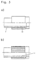
- FIG. 3a shows a modified embodiment Figure 1a with tightly arranged ribs 13 in the assembled Status.
- the shape of the individual ribs 13 is conical to the pipe jacket.
- the large number of ribs 13 results a continuous deformation 14 of the inner tube end 3, such as is shown in Figure 3b and no waveform as in the embodiments of Figures 1b and 2. Dies has a favorable effect on the flow resistance of the pipe.
- FIG. 4a shows a further embodiment of the invention with a conical opening 15 of the sleeve 5 in assembled state and in Figure 4b after the press-cold forming. This creates a deformation of the Inner wall of the pipe end, which has a slight slope 16 has.
- the conical entrance area of the metal sleeve 5 in Pre-assembly condition causes assembly when inserting the Tube in the sleeve is improved. After the cold press molding process causes the slope 16 of the inner wall of the Metal sleeve 5 that vibrations transmitted from the tube become essential due to the conical entrance area be dampened.
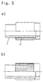
- Figures 5a and 5b show a convex inner wall the metal sleeve 5 before the cold press molding. After the cold forming process the metal sleeve presses against the pipe jacket and creates a convex curved inner shape of the tube.
Abstract
Description
Die Erfindung betrifft eine Verbindung eines Metallrohres mit einer Metallhülse mit Hilfe einer Preß-Kaltverformung und ein Verfahren zur Herstellung einer solchen Rohrverbindung.The invention relates to a connection of a metal tube with a metal sleeve with the help of a cold pressing and a Process for producing such a pipe connection.
Auf dem Gebiet der Schlauchverbindungen für höhere Drucke ist es bekannt, Doppelhülsen als Verbindungselemente zu verwenden, welche aus einer Außen- und einer mit dieser am Ende verbundenen Innenhülse bestehen. Die äußere Hülse weist an ihrer Innenwandung umfangsförmig verlaufende zahnförmige Stege auf. Zur Montage mit einem Schlauchende wird das Verbindungselement bis zu seinem Ende auf das Schlauchende geschoben und mit Hilfe eines Montagegerätes der äußere Mantel auf den Schlauchmantel gepreßt. Das Montagegerät besteht aus einem konischen Werkzeug, das aus mehreren Segmenten besteht und in einem Innenkonus axial verschoben wird. Durch die Verpressung des äußeren Mantels dringen die Zähne in die Oberfläche des Schlauches bis auf seine metallische Seele ein. Dadurch wird die Hülse mit dem Schlauch verbunden und gegenüber der Hülse abgedichtet.In the field of hose connections for higher pressures it is known to use double sleeves as connecting elements, which consists of an outside and one connected to this at the end Inner sleeve exist. The outer sleeve points to her Tooth-shaped webs running circumferentially on the inner wall. The connecting element is used for assembly with a hose end pushed to the end of the hose and with With the help of a mounting device the outer jacket on the hose jacket pressed. The assembly device consists of a conical Tool that consists of several segments and in one Inner cone is moved axially. By pressing the outer shell penetrate the teeth into the surface of the Hose down to its metallic soul. This will the sleeve connected to the hose and opposite the sleeve sealed.
Zur stoßförmigen Verbindung von zwei metallischen Rohren ist es aus der EP 0 470 902 bekannt eine Hülse zu verwenden, welche an ihrer Innenwandung Axialrippen aufweist. Die Hülse besteht aus einer Legierung mit Memory-Effekt bezüglich ihrer Form. Zur Verbindung von zwei Rohren wird die Hülse über die Rohrenden geführt und durch Wärmebehandlung der Memory-Effekt ausgelöst, wodurch die Hülse auf die Rohrenden aufschrumpft und so eine dichte Verbindung herstellt.For the butt joint of two metallic pipes it is known from EP 0 470 902 to use a sleeve, which has axial ribs on its inner wall. The sleeve consists of an alloy with memory effect regarding their Shape. To connect two pipes, the sleeve is over the Guided pipe ends and by heat treatment the memory effect triggered, causing the sleeve to shrink onto the pipe ends and creates a tight connection.
Die vorliegende Erfindung hat es sich zur Aufgabe gemacht, eine Rohrverbindung mittels einer Preß-Kaltverformung herzustellen, welche eine formschlüssige Verbindung darstellt, eine hohe Dichtigkeit und hohe Druckfestigkeit aufweist und durch die Verbindungsmöglichkeit mit allen gängigen Rohranschlußverbindungen vielfältige Anschlußmöglichkeiten bei preiswerter Herstellung bietet.The present invention has set itself the task of to produce a pipe connection by means of a cold press forming, which is a positive connection, a has high tightness and high pressure resistance and through the possibility of connection with all common pipe connection connections diverse connection options at less expensive Manufacturing offers.
Die Lösung dieser Aufgabe besteht bei der eingangs genannten Verbindung eines Metallrohres mit einer Metallhülse darin, daß die Metallhülse auf ihrem Innenmantel mit einem Rohranschlag versehen ist, und der mit dem Rohrende zu verbindende Teil der Hülse auf seinem Innenmantel Verformungen aufweist. Mit Hilfe einer Preß-Kaltverformung unter einem entsprechenden Druck durch ein Montagewerkzeug pressen sich die Verformungen in den Mantel des zu verbindenden Rohres ein und stellen so eine dichte Verbindung zwischen Rohrmantel und Hülse her.The solution to this problem is the one mentioned at the beginning Connection of a metal tube with a metal sleeve in that the metal sleeve on its inner jacket with a pipe stop is provided, and the part of the pipe end to be connected Sleeve has deformations on its inner jacket. With help a press cold forming under a corresponding pressure an assembly tool presses the deformations into the Jacket of the pipe to be connected and so make one tight connection between pipe jacket and sleeve.
In einer Ausführungsform der Erfindung sind die Verformungen des Innenmantels als zueinander parallel angeordnete und um die Achse der Hülse verlaufende Rippen ausgebildet. Durch die Ausübung des Anpreßdruckes verformen sich die Rippen und den Rohrmantel und bilden eine metallische Verbindung. Zwischen den Rippen verbleiben hermetisch geschlossene Dichtungsräume, wodurch eine druckfeste und druckdichte Verbindung von mehreren in Richtung der Rohrachse hintereinanderliegenden metallischen Dichtungen entsteht.In one embodiment of the invention, the deformations of the inner jacket as arranged parallel to each other and around ribs extending the axis of the sleeve. Through the Applying the contact pressure deforms the ribs and the Pipe jacket and form a metallic connection. Between the ribs remain hermetically sealed sealing spaces, creating a pressure-resistant and pressure-tight connection of several metallic one behind the other in the direction of the pipe axis Seals are created.
Die Verformungen und/oder Axialrippen weisen in einer vorteilhaften Abwandlung der Erfindung untereinander einen unterschiedlichen Abstand auf, so daß auch unterschiedlich große hermetisch dichte und hintereinanderliegende Räume entstehen.The deformations and / or axial ribs have an advantageous Modification of the invention with each other a different Distance on, so that different sizes hermetically sealed and successive rooms are created.
Besonders vorteilhaft ist es in der Innenwandung der Hülse eine Ausnehmung zur Aufnahme eines Dichtungsringes vorzusehen, welcher zur Unterstützung der metallischen Dichtungen und zur Erhöhung der Leckagesicherheit eingesetzt wird. Eine solche Ausnehmung ist zweckmäßiger Weise vor der ersten Rippe der Hülse im Bereich des Rohranschlags vorgesehen, so daß die Druckfestigkeit weiter verbessert wird. Als Dichtungselement eignet sich besonders ein Elastomerring. It is particularly advantageous in the inner wall of the sleeve to provide a recess for receiving a sealing ring, which to support the metallic seals and Increased leakage security is used. Such Recess is conveniently in front of the first rib Sleeve provided in the area of the pipe stop, so that the Compressive strength is further improved. As a sealing element an elastomer ring is particularly suitable.
In einer weiteren Abwandlung der Erfindung weisen die Verformungen und Rippen vor der Montage unterschiedliche Höhen auf, die sich bei einer Preß-Kaltverformung in den Mantel des Rohres zu unterschiedlichen Zeiten einpressen und sich dabei auch selbst verformen, so daß eine formschlüssige Verbindung entsteht. Bei einer solchen Ausführungsform wird für den Preßvorgang eine stetig zunehmende Kraft benötigt, da eine zunehmende Anzahl Rippen oder Verformungen in den Preßbereich gelangen. Erst wenn alle Verformungen oder Rippen dem Preßvorgang unterworfen sind, nimmt der Kraftanstieg steil zu, so daß dadurch das Ende der Montage angezeigt wird.In a further modification of the invention, the deformations and ribs of different heights before assembly on, which is in a press cold working in the jacket of Press in the pipe at different times and thereby also deform itself, so that a positive connection arises. In such an embodiment, the Pressing process requires a steadily increasing force, as a increasing number of ribs or deformations in the pressing area reach. Only when all deformations or ribs the pressing process are subject to, the increase in force increases steeply, so that this indicates the end of the assembly.
Bei einer weiteren Ausführungsform weist die Hülse einen konisch verlaufenden Eingangsbereich auf, dem sich eine Anzahl Verformungen und/oder Rippen anschließen. Hierdurch wird die Montage beim Einführen des Rohres in die Hülse verbessert. Wesentlich ist es jedoch, daß Schwingungen, welche vom Rohr übertragen werden, durch den konisch verlaufenden Eingangsbereich wesentlich gedämpft werden.In a further embodiment, the sleeve has one conical entrance area on which a number Connect deformations and / or ribs. This will make the Assembly when inserting the tube into the sleeve improved. It is essential, however, that vibrations from the pipe are transmitted through the conical entrance area be dampened significantly.
Die Verformung des Innenmantels der Hülse ist in einer weiteren Ausführungsform als eine konvexe Wölbung ausgebildet, so das nach der Verpressung eine Reibschlüssige Verbindung entsteht. Zur Erhöhung des Reibwertes ist die Fläche der konvexen Wölbung in an sich bekannter Weise aufgerauht.The deformation of the inner shell of the sleeve is in another Embodiment designed as a convex curvature, so that a frictional connection is created after pressing. To increase the coefficient of friction, the surface is convex Roughened in a conventional manner.
Zur weiteren Erhöhung des Reibwertes ist die Fläche der konvexen Wölbung mit einem mikroverkapselten Kleber beschichtet. In Abwandlung hierzu kann auch die Innenfläche der Hülse mit einem harten und körnigen Granulat beschichtet werden.To further increase the coefficient of friction, the surface is convex Dome coated with a microencapsulated adhesive. In a modification of this, the inner surface of the sleeve can also be used hard and granular granules.
Die Metallhülse ist in einer konkreten Ausführungsform mit einem Rohrverschraubungsanschluß kombiniert.The metal sleeve is in a specific embodiment with combined a pipe screw connection.
Gründsätzlich läßt sich die Verbindung nach der Erfindung mit allen auf dem Markt befindlichen Rohrverschraubungssystemen kombinieren. Basically, the connection according to the invention with all pipe fitting systems on the market combine.
Die mit dem Rohrende zu verbindende Metallhülse wird gemäß dem Verfahren zur Herstellung der Rohrverbindung auf das Rohrende bis zu ihrem Anschlag geschoben und sodann einem Preßdruck ausgesetzt, derart, daß die Verformungen und/oder Rippen der Hülse sich und den Rohrmantel plastisch verformen. Hierzu können Schlauchpressen verwendet werden, wie sie an sich auf dem Markt erhältlich sind, jedoch sind deren Arbeitsdrucke entsprechend zu verstärken oder es sind spezielle Werkzeugeinsätze zu verwenden.The metal sleeve to be connected to the pipe end is according to the Method of making the pipe joint on the pipe end pushed until it stops and then a pressure exposed such that the deformations and / or ribs of the Plastically deform the sleeve and the pipe jacket. For this hose presses can be used as they are per se are available on the market, however, are their working prints reinforce accordingly or there are special tool inserts to use.
Die Erfindung wird anhand der Zeichnungen näher erläutert. Hierbei zeigen:
FIGUR 1- a) eine Hülse mit einer Anschlußverschraubung
und einem in der Hülse befindlichen
Rohrende in Seitenansicht und Teilschnitt
und
b) Figur 1a im montierten Zustand in entsprechender Darstellung ohne Anschlußverschraubung; FIGUR 2- eine Ausführungsform nach
Figur 1 mit zusätzlicher Ringdichtung; FIGUR 3- a) eine abgewandelte Ausführungsform nach
Figur 1a mit dicht angeordneten Rippen im
zusammengesteckten Zustand;
b) die Ausführungsform nach Figur 3a in montierter Form nach dem Preßvorgang; FIGUR 4- a) eine weitere Ausführungsform mit einer
konisch ausgebildeten Öffnung der Hülse
im zusammengesteckten Zustand;
b) die Ausführungsform nach Figur 4a in montierter Form nach dem Preßvorgang; FIGUR 5- a) ein noch anderes Ausführungsbeispiel mit
einer konvex geformten Innenseite der
Hülse im zusammengesteckten Zustand, und
b) Figur 5a im montierten Zustand.
- FIGURE 1
- a) a sleeve with a screw connection and a tube end located in the sleeve in side view and partial section and
b) Figure 1a in the assembled state in a corresponding representation without screw connection; - FIGURE 2
- an embodiment of Figure 1 with additional ring seal;
- FIGURE 3
- a) a modified embodiment according to Figure 1a with tightly arranged ribs in the assembled state;
b) the embodiment according to FIG. 3a in assembled form after the pressing process; - FIGURE 4
- a) another embodiment with a conical opening of the sleeve in the assembled state;
b) the embodiment according to FIG. 4a in assembled form after the pressing process; - FIGURE 5
- a) yet another embodiment with a convex shaped inside of the sleeve in the assembled state, and
b) Figure 5a in the assembled state.
Die Figur 1a zeigt eine Hülse 1 mit einer Anschlußverschraubung
2 und einem in der Hülse befindlichen Rohrende 3 in
Seitenansicht und im Teilschnitt. Das Rohrende 3 ist bis an
den Anschlag 4 in der Metallhülse 5 geführt. Die Anschlußverschraubung
2 besteht aus einer Überwurfmutter, welche die
Metallhülse 5 über einen Sprengring 6 erfaßt. Das Innengewinde
7 der Überwurfmutter wird mit einem nicht näher dargestellten
Außengewinde eines Verbindungselements verbunden, wobei ein
O-Ring 8 an die Innenwandung des Verbindungselements zur
Anlage kommt. Die Metallhülse 5 weist in dem Bereich, der sich
über das Rohrende 3 erstreckt, Rippen 9 auf.Figure 1a shows a
Die Figur 1b zeigt die Rohrverbindung nach der Kalt-Preßverformung.
Die Rippen 9 wurden hierbei derart plastisch verformt,
daß auch eine geringe innere Rohrverformung stattfand,
wie durch die Bezugsziffer 10 angedeutet ist. Durch den Preßvorgang
sind die zwischen den Rippen 9 befindlichen Räume hermetisch
abgedichtet.FIG. 1b shows the pipe connection after the cold compression molding.
The
Die Figur 2 zeigt, ähnlich wie Figur 1b, eine Metallhülse 5,
verbunden mit einem Rohrende 3 nach einer Preß-Kaltverformung.
Bei dieser Ausführungsform befindet sich in der Metallhülse
5 eine Nut 11 zur Aufnahme einer Elastomerdichtung 12.2 shows, similar to FIG. 1b, a
Die Figur 3a zeigt eine abgewandelte Ausführungsform nach
Figur 1a mit dicht angeordneten Rippen 13 im zusammengesteckten
Zustand. Die Form der einzelnen Rippen 13 verläuft konisch
zum Rohrmantel. Durch die Vielzahl der Rippen 13 ergibt sich
eine durchgehende Verformung 14 des inneren Rohrendes 3, wie
in der Figur 3b dargestellt ist und keine Wellenform wie bei
den Ausführungsbeispielen nach den Figuren 1b und 2. Dies
wirkt sich günstig auf den Strömungswiderstand des Rohres aus. FIG. 3a shows a modified embodiment
Figure 1a with tightly arranged
Die Figur 4a zeigt eine weitere Ausführungsform der Erfindung
mit einer konisch ausgebildeten Öffnung 15 der Hülse 5 im
zusammengesteckten Zustand und in Figur 4b nach der Preß-Kaltverformung.
Hierbei bildet sich eine Verformung der
Innenwandung des Rohrendes aus, welche eine leichte Steigung
16 aufweist.FIG. 4a shows a further embodiment of the invention
with a
Der konisch verlaufende Eingangsbereich der Metallhülse 5 im
Vormontagezustand bewirkt, daß die Montage beim Einführen des
Rohres in die Hülse verbessert wird. Nach dem Preß-Kaltverformungsprozeß
bewirkt die Steigung 16 der Innenwandung der
Metallhülse 5, daß Schwingungen, welche vom Rohr übertragen
werden, durch den konisch verlaufenden Eingangsbereich wesentlich
gedämpft werden.The conical entrance area of the
Die Figuren 5a und 5b zeigen eine konvex geformte Innenwandung
der Metallhülse 5 vor der Preß-Kaltverformung. Nach dem Kaltverformungsvorgang
preßt sich die Metallhülse an den Rohrmantel
und bewirkt eine konvexe gewölbte Innenform des Rohres.Figures 5a and 5b show a convex inner wall
the
Mit der Erfindung wird eine Rohranschlußverbindung geschaffen, welche sich leicht herstellen läßt, sicher und dicht für höchste Drucke ist und damit hohen Anforderungen genügt.With the invention, a pipe connection is created which is easy to manufacture, safe and leakproof for is the highest pressure and therefore meets high requirements.
Claims (12)
Applications Claiming Priority (2)
| Application Number | Priority Date | Filing Date | Title |
|---|---|---|---|
| DE19740144A DE19740144C2 (en) | 1997-09-12 | 1997-09-12 | Connection of a metal tube with a metal sleeve, and method for producing the connection |
| DE19740144 | 1997-09-12 |
Publications (1)
| Publication Number | Publication Date |
|---|---|
| EP0902226A1 true EP0902226A1 (en) | 1999-03-17 |
Family
ID=7842155
Family Applications (1)
| Application Number | Title | Priority Date | Filing Date |
|---|---|---|---|
| EP98116756A Withdrawn EP0902226A1 (en) | 1997-09-12 | 1998-09-04 | Connection of a metal pipe with a metal sleeve |
Country Status (9)
| Country | Link |
|---|---|
| US (1) | US6619701B1 (en) |
| EP (1) | EP0902226A1 (en) |
| JP (1) | JPH11141758A (en) |
| CN (1) | CN1214429A (en) |
| AR (1) | AR009691A1 (en) |
| AU (1) | AU750404B2 (en) |
| BR (1) | BR9803407A (en) |
| CA (1) | CA2246936A1 (en) |
| DE (1) | DE19740144C2 (en) |
Cited By (1)
| Publication number | Priority date | Publication date | Assignee | Title |
|---|---|---|---|---|
| DE20108973U1 (en) * | 2001-05-29 | 2002-10-02 | Interforge Klee Gmbh | Metallic pipe connector |
Families Citing this family (28)
| Publication number | Priority date | Publication date | Assignee | Title |
|---|---|---|---|---|
| DE10019388A1 (en) * | 2000-04-19 | 2001-10-31 | Parker Hannifin Gmbh | Positively engaged, releasable hydraulic pipe connection is formed with connecting body, wrap or screwing nut and press ring which in fitted state has at least one bulge running over its inner periphery |
| DE10207201A1 (en) * | 2002-02-21 | 2003-09-04 | Welcker F | Connecting sleeve fits over pipe and has circumferential groove containing metal clamping ring |
| DE10214997B4 (en) * | 2002-04-05 | 2005-04-07 | Voswinkel Kg | Hydraulic connector device |
| WO2005080815A1 (en) * | 2004-02-19 | 2005-09-01 | Ernst Grob Ag | Tooth profile of a spline shaft |
| DE102004035354B3 (en) * | 2004-07-21 | 2006-02-02 | Parker Hannifin Gmbh | Plug connection for metal pipes |
| US20060131877A1 (en) * | 2004-12-21 | 2006-06-22 | The Boeing Company | Electromagnetic mechanical pulse forming of fluid joints for high-pressure applications |
| US20060208481A1 (en) * | 2004-12-22 | 2006-09-21 | The Boeing Company | Electromagnetic pulse welding of fluid joints |
| US7513025B2 (en) * | 2004-12-28 | 2009-04-07 | The Boeing Company | Magnetic field concentrator for electromagnetic forming |
| US20060145474A1 (en) * | 2005-01-03 | 2006-07-06 | Allen Fischer | Electromagnetic mechanical pulse forming of fluid joints for low-pressure applications |
| DE102005043238B4 (en) * | 2005-09-09 | 2012-11-08 | Sanha Gmbh & Co. Kg | pipe connection |
| FR2899307B1 (en) * | 2006-03-29 | 2012-02-03 | Permaswage | WASTE CONNECTING ACCESSORY FOR PIPES |
| US7954861B2 (en) * | 2007-02-23 | 2011-06-07 | The Gates Corporation | Crimped/swaged-on tubing terminations and methods |
| US7530604B2 (en) * | 2007-05-15 | 2009-05-12 | Ti Group Automotive Systems, Llc | Non-serviceable fluid coupling |
| US8113550B2 (en) * | 2007-12-10 | 2012-02-14 | Nibco Inc. | Connection with tail piece for a press-fitting |
| US8925978B2 (en) * | 2008-07-31 | 2015-01-06 | Mueller Industries, Inc. | Coupling and joint for fixedly and sealingly securing components to one another |
| DE102008047003A1 (en) | 2008-09-12 | 2010-03-18 | Contitech Techno-Chemie Gmbh | Non-detachable pipe connection |
| CN101625054B (en) * | 2009-08-20 | 2012-10-03 | 中舟海洋科技(上海)有限公司 | Radial extrusion type joint |
| BR112012024037B1 (en) * | 2010-03-26 | 2020-09-01 | Snecma | DEGASIFICATION TUBE FOR THE GUIDANCE OF A GAS FLOW IN A TURBORREATOR, TURBORREACTOR AND METHOD OF ASSEMBLING A SAID DEGASIFICATION TUBE FOR THE ORIENTATION OF A GAS FLOW WITHIN A ROTATING OXIDE OF A TURBO. |
| SE535187C2 (en) * | 2010-09-10 | 2012-05-15 | Fumex Ab | Joint construction, ventilation arm and ventilation system |
| EP2600049A1 (en) * | 2011-11-29 | 2013-06-05 | Eaton Germany GmbH | Crimp connection arrangement for pressurised pipes |
| US9481024B1 (en) | 2013-03-21 | 2016-11-01 | Davor Petricio Yaksic | Pipe joining |
| PT3015751T (en) * | 2014-10-31 | 2018-01-09 | Apex Gold International Ltd | Fitting for connecting to a tubular element, tubing connection and a method for connecting a fitting to a tubular element |
| US9982813B2 (en) * | 2015-03-27 | 2018-05-29 | Designed Metal Connections, Inc. | Swage fitting |
| US10240698B2 (en) | 2016-02-17 | 2019-03-26 | Nibco Inc. | Crimp connection with one or more crimping elements |
| US10823316B2 (en) | 2017-04-28 | 2020-11-03 | Nibco Inc. | Piping connections and connection sockets |
| US10895338B2 (en) | 2017-04-28 | 2021-01-19 | Nibco Inc. | Enhanced end design for tubular press connections |
| US10865914B2 (en) | 2017-04-28 | 2020-12-15 | Nibco Inc. | High temperature leak prevention for piping components and connections |
| EP3822604A4 (en) * | 2018-07-13 | 2022-05-18 | Nidec Copal Electronics Corporation | Torque sensor attachment structure |
Citations (5)
| Publication number | Priority date | Publication date | Assignee | Title |
|---|---|---|---|---|
| IT455785A (en) * | ||||
| US4527820A (en) * | 1983-03-14 | 1985-07-09 | Gibson Jack Edward | Postive seal steel coupling apparatus and method |
| EP0470902A1 (en) | 1990-08-06 | 1992-02-12 | The Furukawa Electric Co., Ltd. | Liner for pipe joint by use of shape memory alloy |
| WO1992003681A1 (en) * | 1990-08-24 | 1992-03-05 | Lokring Corporation | Pipe fitting body with isolation tooth arrangement |
| EP0797037A2 (en) * | 1996-03-18 | 1997-09-24 | GIACOMINI S.p.A. | Quickly assembled pipe connection |
Family Cites Families (19)
| Publication number | Priority date | Publication date | Assignee | Title |
|---|---|---|---|---|
| US2583956A (en) * | 1947-04-03 | 1952-01-29 | Chicago Metal Hose Corp | Coupling structure |
| US2848254A (en) * | 1950-05-01 | 1958-08-19 | Millar John Humphrey | End fittings for flexible metallic hose |
| FR1238027A (en) * | 1958-10-01 | 1960-08-05 | Carlsson & Larsson Ab | Improvements made to tube couplings |
| US3397901A (en) * | 1966-12-01 | 1968-08-20 | Harlan J. Larrivee | Bushing assembly for engaging relatively rigid cylindrical bodies |
| US3498648A (en) * | 1968-08-22 | 1970-03-03 | Boeing Co | High temperature and pressure tube fitting |
| SE434564B (en) * | 1975-04-09 | 1984-07-30 | Raychem Corp | DEVICE FOR CONNECTING RODS OR OTHER SUBSTRATES INCLUDING A MEMORIAL METAL BODY |
| JPS5560784A (en) * | 1978-10-27 | 1980-05-08 | Co Metaru Components Deibijiyo | Fluid joint |
| DE3149596A1 (en) * | 1981-12-15 | 1983-06-23 | Uni-Cardan Ag, 5200 Siegburg | CONNECTING PARTS |
| US4431031A (en) * | 1982-03-29 | 1984-02-14 | Amco Corporation | Pre-rinse hose |
| US4768275A (en) * | 1984-09-10 | 1988-09-06 | Cameron Iron Works, Inc. | Method of joining pipe |
| US4671542A (en) * | 1984-12-17 | 1987-06-09 | Dana Corporation | Swivel hose coupling assembly and method |
| AU6531090A (en) * | 1990-03-20 | 1991-10-21 | Deutsch Company, The | Swagable fitting |
| US5364134A (en) * | 1991-04-26 | 1994-11-15 | Anderson Barrows Metal Corporation | End fitting for flexible conduit |
| US5267758A (en) * | 1991-07-18 | 1993-12-07 | The Gates Rubber Company | Ferrule coupling having a C-shaped insert |
| US5190324A (en) * | 1991-11-06 | 1993-03-02 | M&Fc Holding Company, Inc. | Pipe restraining member |
| WO1996008669A1 (en) * | 1994-09-12 | 1996-03-21 | Alfred Kärcher GmbH & Co. | Connector piece for the hose coupling of high-pressure cleaning equipment |
| DE29504502U1 (en) * | 1995-03-20 | 1995-05-11 | Ruhnke Michael | Pressable fittings made of malleable cast iron |
| US5553898A (en) * | 1995-06-30 | 1996-09-10 | The Pipe Line Development Company | Hot-tapping sleeve |
| US6092274A (en) * | 1998-02-26 | 2000-07-25 | 40 Properties Management, Ltd | Metal hose fitting and method of making |
-
1997
- 1997-09-12 DE DE19740144A patent/DE19740144C2/en not_active Expired - Fee Related
-
1998
- 1998-08-26 AR ARP980104248A patent/AR009691A1/en unknown
- 1998-09-04 EP EP98116756A patent/EP0902226A1/en not_active Withdrawn
- 1998-09-09 BR BR9803407-3A patent/BR9803407A/en not_active Application Discontinuation
- 1998-09-10 US US09/151,197 patent/US6619701B1/en not_active Expired - Fee Related
- 1998-09-11 CA CA002246936A patent/CA2246936A1/en not_active Abandoned
- 1998-09-11 JP JP10257971A patent/JPH11141758A/en active Pending
- 1998-09-11 CN CN98119139.8A patent/CN1214429A/en active Pending
- 1998-09-14 AU AU84211/98A patent/AU750404B2/en not_active Ceased
Patent Citations (5)
| Publication number | Priority date | Publication date | Assignee | Title |
|---|---|---|---|---|
| IT455785A (en) * | ||||
| US4527820A (en) * | 1983-03-14 | 1985-07-09 | Gibson Jack Edward | Postive seal steel coupling apparatus and method |
| EP0470902A1 (en) | 1990-08-06 | 1992-02-12 | The Furukawa Electric Co., Ltd. | Liner for pipe joint by use of shape memory alloy |
| WO1992003681A1 (en) * | 1990-08-24 | 1992-03-05 | Lokring Corporation | Pipe fitting body with isolation tooth arrangement |
| EP0797037A2 (en) * | 1996-03-18 | 1997-09-24 | GIACOMINI S.p.A. | Quickly assembled pipe connection |
Cited By (1)
| Publication number | Priority date | Publication date | Assignee | Title |
|---|---|---|---|---|
| DE20108973U1 (en) * | 2001-05-29 | 2002-10-02 | Interforge Klee Gmbh | Metallic pipe connector |
Also Published As
| Publication number | Publication date |
|---|---|
| CN1214429A (en) | 1999-04-21 |
| JPH11141758A (en) | 1999-05-28 |
| CA2246936A1 (en) | 1999-03-12 |
| AU750404B2 (en) | 2002-07-18 |
| BR9803407A (en) | 1999-11-09 |
| US6619701B1 (en) | 2003-09-16 |
| AR009691A1 (en) | 2000-04-26 |
| DE19740144C2 (en) | 1999-12-02 |
| DE19740144A1 (en) | 1999-03-18 |
| AU8421198A (en) | 1999-03-25 |
Similar Documents
| Publication | Publication Date | Title |
|---|---|---|
| EP0902226A1 (en) | Connection of a metal pipe with a metal sleeve | |
| EP1070215B1 (en) | Device for connecting a pipe socket, a tubular mounting part or a fitting to a pipe | |
| DE102007025931B3 (en) | Clamp fitting for a pipe | |
| EP0555650B1 (en) | Adaptive device for pipe couplings | |
| EP1470356B1 (en) | Press connection | |
| DE19702289A1 (en) | Arrangement for plug-in connection of pipe or hose with valve or fittings | |
| DE3521178C2 (en) | ||
| EP3322923B1 (en) | Sanitary line attachment | |
| DE19840668C1 (en) | Press fit pipe coupling | |
| EP1265018B1 (en) | Pipe assembly arrangement | |
| DE2332241C3 (en) | Pipe connection | |
| DE4116610A1 (en) | Pipe coupling for high pressure small diameter pipes - has sealing ring with teeth which bite into pipe surface | |
| DE4325349C2 (en) | Connecting device | |
| DE19757946C2 (en) | pipe connection | |
| DE2735704A1 (en) | HOSE CONNECTOR AND METHOD FOR ASSEMBLING A HOSE WITH A CONNECTOR | |
| DE19516830A1 (en) | Pressing tools and methods for connecting tubular elements | |
| DE10108309C1 (en) | Pipe coupling for deformable pipe incorporates deformable plastics seal moved in opposite direction to pipe end by axial compression | |
| DE3130922C1 (en) | Screw system | |
| EP0454976B1 (en) | Connecting device between a pipe of plastic material and another pipe | |
| DE3047382A1 (en) | Pipe union with clamped bush - has clamping members formed by washers with central cone portions | |
| EP3338018B1 (en) | Connecting arrangement with press ring | |
| WO2000028250A1 (en) | Press-fitted pipe joint | |
| AT500173B1 (en) | CLAMPING DEVICE FOR CONNECTING A TUBING TO A HYDRAULIC TUBE | |
| DE2315196A1 (en) | RADIATOR PLUG AND METHOD OF MANUFACTURING SUCH | |
| DE2045132B2 (en) | Pipe sealing ring for high thermal loads - has elastic body fitting inside semi-toroidal axial wall |
Legal Events
| Date | Code | Title | Description |
|---|---|---|---|
| PUAI | Public reference made under article 153(3) epc to a published international application that has entered the european phase |
Free format text: ORIGINAL CODE: 0009012 |
|
| AK | Designated contracting states |
Kind code of ref document: A1 Designated state(s): AT CH DE FI FR GB IT LI SE |
|
| AX | Request for extension of the european patent |
Free format text: AL;LT;LV;MK;RO;SI |
|
| 17P | Request for examination filed |
Effective date: 19990403 |
|
| AKX | Designation fees paid |
Free format text: AT CH DE FI FR GB IT LI SE |
|
| 17Q | First examination report despatched |
Effective date: 20000630 |
|
| STAA | Information on the status of an ep patent application or granted ep patent |
Free format text: STATUS: THE APPLICATION IS DEEMED TO BE WITHDRAWN |
|
| 18D | Application deemed to be withdrawn |
Effective date: 20021206 |