EP0902219B1 - Shift rail detent assembly - Google Patents
Shift rail detent assembly Download PDFInfo
- Publication number
- EP0902219B1 EP0902219B1 EP98116521A EP98116521A EP0902219B1 EP 0902219 B1 EP0902219 B1 EP 0902219B1 EP 98116521 A EP98116521 A EP 98116521A EP 98116521 A EP98116521 A EP 98116521A EP 0902219 B1 EP0902219 B1 EP 0902219B1
- Authority
- EP
- European Patent Office
- Prior art keywords
- shift
- engaged
- disengaged position
- detent mechanism
- condition
- Prior art date
- Legal status (The legal status is an assumption and is not a legal conclusion. Google has not performed a legal analysis and makes no representation as to the accuracy of the status listed.)
- Expired - Lifetime
Links
Images


Classifications
-
- F—MECHANICAL ENGINEERING; LIGHTING; HEATING; WEAPONS; BLASTING
- F16—ENGINEERING ELEMENTS AND UNITS; GENERAL MEASURES FOR PRODUCING AND MAINTAINING EFFECTIVE FUNCTIONING OF MACHINES OR INSTALLATIONS; THERMAL INSULATION IN GENERAL
- F16H—GEARING
- F16H61/00—Control functions within control units of change-speed- or reversing-gearings for conveying rotary motion ; Control of exclusively fluid gearing, friction gearing, gearings with endless flexible members or other particular types of gearing
- F16H61/24—Providing feel, e.g. to enable selection
-
- F—MECHANICAL ENGINEERING; LIGHTING; HEATING; WEAPONS; BLASTING
- F16—ENGINEERING ELEMENTS AND UNITS; GENERAL MEASURES FOR PRODUCING AND MAINTAINING EFFECTIVE FUNCTIONING OF MACHINES OR INSTALLATIONS; THERMAL INSULATION IN GENERAL
- F16H—GEARING
- F16H63/00—Control outputs from the control unit to change-speed- or reversing-gearings for conveying rotary motion or to other devices than the final output mechanism
- F16H63/02—Final output mechanisms therefor; Actuating means for the final output mechanisms
- F16H63/30—Constructional features of the final output mechanisms
- F16H63/34—Locking or disabling mechanisms
-
- F—MECHANICAL ENGINEERING; LIGHTING; HEATING; WEAPONS; BLASTING
- F16—ENGINEERING ELEMENTS AND UNITS; GENERAL MEASURES FOR PRODUCING AND MAINTAINING EFFECTIVE FUNCTIONING OF MACHINES OR INSTALLATIONS; THERMAL INSULATION IN GENERAL
- F16H—GEARING
- F16H63/00—Control outputs from the control unit to change-speed- or reversing-gearings for conveying rotary motion or to other devices than the final output mechanism
- F16H63/02—Final output mechanisms therefor; Actuating means for the final output mechanisms
- F16H63/30—Constructional features of the final output mechanisms
- F16H63/38—Detents
-
- Y—GENERAL TAGGING OF NEW TECHNOLOGICAL DEVELOPMENTS; GENERAL TAGGING OF CROSS-SECTIONAL TECHNOLOGIES SPANNING OVER SEVERAL SECTIONS OF THE IPC; TECHNICAL SUBJECTS COVERED BY FORMER USPC CROSS-REFERENCE ART COLLECTIONS [XRACs] AND DIGESTS
- Y10—TECHNICAL SUBJECTS COVERED BY FORMER USPC
- Y10T—TECHNICAL SUBJECTS COVERED BY FORMER US CLASSIFICATION
- Y10T74/00—Machine element or mechanism
- Y10T74/19—Gearing
- Y10T74/19219—Interchangeably locked
- Y10T74/19251—Control mechanism
-
- Y—GENERAL TAGGING OF NEW TECHNOLOGICAL DEVELOPMENTS; GENERAL TAGGING OF CROSS-SECTIONAL TECHNOLOGIES SPANNING OVER SEVERAL SECTIONS OF THE IPC; TECHNICAL SUBJECTS COVERED BY FORMER USPC CROSS-REFERENCE ART COLLECTIONS [XRACs] AND DIGESTS
- Y10—TECHNICAL SUBJECTS COVERED BY FORMER USPC
- Y10T—TECHNICAL SUBJECTS COVERED BY FORMER US CLASSIFICATION
- Y10T74/00—Machine element or mechanism
- Y10T74/20—Control lever and linkage systems
- Y10T74/20012—Multiple controlled elements
- Y10T74/20018—Transmission control
- Y10T74/20085—Restriction of shift, gear selection, or gear engagement
- Y10T74/20104—Shift element interlock
- Y10T74/2011—Shift element interlock with detent, recess, notch, or groove
Definitions
- the present invention relates to shift rail detent mechanisms for providing a selectively variable resistance to axial or rotational movement of a shift rail for minimizing the occurrence of jumpout.
- the present invention relates to such a detent mechanism for a lever-shifted transmission system having means to determine a driver intent to initiate a lever shift and, upon sensing such an intent, to cause the detent mechanism to provide a decreased resistance to shift rail movement.
- the prior art manually shifted transmissions especially as utilized for heavy-duty vehicles such as straight trucks and conventional (i.e ., not cab-over-engine) tractor/semi-trailers, utilized a manually manipulated shift lever extending upwardly from a shift tower subassembly mounted directly on the transmission housing and interacted with a multiple-rail or single shift shaft shifting mechanism of the types shown in U.S. Pats. No. 4,455,883; 4,550,627; 4,920,815 and 5,272,931.
- shift rail detent mechanisms are used to maintain the shift rails in a fixed position to resist jumpout, such as shift lever-induced jumpout. Examples of such detent mechanisms may be seen by reference to U.S. Pats. No. 4,550,627; 4,614,126; 4,920,815; 5,000,060 and 5,350,561. Such mechanisms are not totally satisfactory, as the magnitude of resistance to shift rail movement needed to provide a significant resistance to jumpout often objectionably increased the operator effort associated with a lever shift.
- DE-A-3 315 221 describes a multiple speed mechanical transmission system comprising a shift rail, a detent mechanism for said shift rail, and a sensor which senses the position of the shift rail and provides corresponding position signals.
- a control unit processes said position signals and operates said detent mechanism as to reduce the detent force when said shift rail is being shifted and to enlarge the detent force at the detent positions.
- a similar detent mechanism is described in FR-A-2 645 233, whereas instead of the position of the shift rail the operation of the clutch pedal is taken as an indication of the need to vary the detent force.
- Partially automated mechanical transmission systems providing automatic assistance, such as automatic engine fuel control, for manual lever-shifted transmissions are known in the prior art, as may be seen by reference to U.S. Pats. No. 4,593,580; 5,569,115; 5,571,059; 5,573,477 and 5,582,558.
- These systems utilize automatic engine fueling controls and/or range and/or splitter shift actuators, actuated by a driver indication of an intent to shift, allowing an old gear to be disengaged and a new or target gear to be engaged without requiring the driver to manipulate the clutch pedal (required only for vehicle launch and stop) or the throttle pedal.
- the drawbacks of the prior art are minimized or overcome by the provision of a selectively variable detent mechanism for a transmission system having a means independent of operation of said shift member and said master friction clutch for sensing a driver intent to initiate a lever shift, which provides a significant resistance to shift lever-induced jumpout without objectionably increasing the operator effort required to make an intended lever shift.
- a detent mechanism which may be controlled to a first condition for providing a greater resistance to shift rail movement or to a second condition for providing a lesser resistance to shift rail movement.
- the detent mechanism Upon determining a driver intent to initiate a lever shift, and preferably until confirming engagement of a target gear ratio, the detent mechanism is caused to assume the second condition wherein detent resistance to shift rail movement (and, thus, to lever shifts) is minimized.
- the detent mechanism is caused to assume the first condition wherein a significant detent resistance to shift rail movement (and, thus, to shift lever-induced jumpout) is applied.
- the preferred embodiment of the present invention is illustrated as utilized in a partially automated, lever-shifted mechanical transmission system of the type illustrated in aforementioned U.S. Pats. No. 4,593,580; 5,569,115 and 5,582,558. Although the present invention is particularly advantageously utilized in such systems, its application is not so limited.
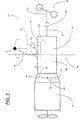
- a typical vehicular powertrain system 10 advantageously utilizing the present invention may be seen by reference to Fig. 1.
- Powertrain 10 is of the type commonly utilized in heavy-duty vehicles, such as the conventional tractors of tractor/semi-trailer vehicles, and includes an engine, typically a diesel engine, 12, a master friction clutch 14 contained within a clutch housing, a multiple-speed compound transmission 16, and a drive axle assembly 18.
- the transmission 16 includes an output shaft 20 drivingly coupled to a vehicle drive shaft 22 by a universal joint 24 for driving the drive axle assembly, as is well known in the prior art.
- the transmission 16 is housed within a transmission housing 26 to which is directly mounted the shift tower 28 of the shift lever assembly 30.
- Fig. 4A illustrates a shift pattern for assisted manual shifting of a combined range-and-splitter-type compound transmission manually shifted by a manually operated shift lever.
- the shift lever 31 is movable in the side-to-side or X-X direction to select a particular ratio or ratios to be engaged and is movable in the fore and aft or Y-Y direction to selectively engage and disengage the various ratios.
- the shift pattern may include an automatic range shifting feature and automatically selected and/or implemented splitter shifting, as is known in the prior art. Manual transmissions utilizing shift mechanisms and shift patterns of this type are well known in the prior art and may be appreciated in greater detail by reference to aforementioned U.S. Pats. No. 5,000,060 and 5,390,561.
- the shift lever assembly 30 will include a shift finger or the like (not shown) extending downwardly into a shifting mechanism 32, such as multiple-rail shift bar housing assembly or a single shift shaft assembly, as is well known in the prior art and as is illustrated in aforementioned U.S. Pats. No. 4,455,883; 4,550,627; 4,920,815 and 5,272,931.
- shift lever jumpout is the unintended disengagement of the jaw clutches of a manually shifted transmission caused by shift lever oscillations in the Y-Y direction about the Y-Y pivot axis 34 of the shift lever assembly. It is the purpose of the shift rail detent assembly of the present invention to minimize the occurrences of such shift lever-induced jumpout while not objectionably increasing shift effort.
- the engine-clutch-transmission assemblage will tend to move, during severe road conditions, in a vertical manner (as illustrated by arrow 36) and in a pivoting manner about a pivot point or axis 38 (usually located in the area of the vehicle clutch).
- a pivot point or axis 38 usually located in the area of the vehicle clutch.
- an upward movement of the assemblage almost always is associated with a counterclockwise rotation of the assemblage around pivot axis 38, while, as indicated by arrow 42, a downward movement of the assemblage almost always is accompanied by a clockwise rotation of the assemblage about the pivot axis 38.
- shift lever-induced jumpout is forced by the inertial effects of excessive road-induced vibration in the vehicle drive train.
- This road-induced shock causes the engine-clutch-transmission assemblage to pitch on its mounts, as shown in Fig. 1.
- This pitching occurs at the natural frequency of the engine-clutch-transmission-mount system, usually between about 7 and 10 HZ.
- This pitching induces relatively high vertical, fore-aft and rotational accelerations on the transmission and, in particular, the shift lever assembly.
- the shift lever assembly then develops an inertial jumpout torque T J about its pivot 34 as determined by the sum of the inertial torques thereon, as will be described in greater detail below and as schematically illustrated in Fig. 2. It is noted that the typical rearward offset in transmission lever tends to increase the jumpout torque.
- jumpout torque T J is resisted by the shift rail or shift shaft detent force multiplied by its moment arm determined by the distance between the pivot 34 and the shift rail or shaft (i.e., detent torque T O ).
- Detent force may include the forces required to overcome a detent mechanism, torque lock in the engaged jaw clutches, and frictional forces in the shift mechanism.
- shift lever jumpout occurs. This tends to occur when the drive train has a very low torque, such as vehicle coast conditions, since the friction from so-called torque lock in the drive train during driving conditions tends to lock the engaged sliding clutch members in engagement and greatly overcomes any jumpout forces imposed thereon.
- the shift lever assembly 30 itself is a dynamic system, it has its own natural frequency. Unfortunately, this also usually occurs between 7 and 10 HZ. This frequency is determined by lever height, lever offset, tower height, and isolator stiffness. If the natural frequency of the engine-clutch-transmission assemblage matches that of the shift lever assembly, propensity for jumpout is greater because the engine-amplified inertial forces are amplified further by the lever resonance.
- Fig. 2 illustrates a mathematical model for calculating the jumpout torque T J induced in a shift rail by shift lever whip. It is noted that jumpout torque will be applied in both the counterclockwise and clockwise directions about the shift lever pivot axis 34 but will tend to cause jumpout only in one of those two directions, depending upon the currently engaged gear ratio.
- the forward shifting of transmission 16 comprising main section 16A coupled to auxiliary section 16B, is semi-automatically implemented/assisted by the vehicular semi-automatic transmission system 100, illustrated in Figs. 4A-4C.
- Main section 16A includes an input shaft 50, which is operatively coupled to the drive or crank shaft 110 of the vehicle engine 12 by master clutch 14, and output shaft 20 of auxiliary section 16B is operatively coupled, commonly by means of a drive shaft, to the drive wheels of the vehicle.
- the auxiliary section 16B is a splitter type, preferably a combined range-and-splitter type, as illustrated in U.S. Pat. No. 5,390,561.
- the change-gear ratios available from main transmission section 16 are manually selectable by manually positioning the shift lever 31 according to the shift pattern prescribed to engage the particular change gear ratio of main section 16A desired.
- manipulation of the master clutch other than when bringing the vehicle to or when launching the vehicle from an at-rest condition
- manual synchronizing are not required.
- the system includes means to signal an intent to shift into a target ratio and will automatically take actions to minimize or relieve torque-lock conditions, allowing, if required, an easier shift into main section neutral from the engaged main section ratio and further allowing required splitter shifts to be automatically and rapidly completed upon a shift into neutral.
- the system Upon sensing a neutral condition, the system will cause the engine to rotate at a substantially synchronous speed for engaging a target gear ratio.
- the system 100 includes sensors 106 for sensing engine rotational speed (ES), 108 for sensing input shaft rotational speed (IS), and 110 for sensing output shaft rotational speed (OS) and providing signals indicative thereof.
- ES engine rotational speed
- IS input shaft rotational speed
- OS output shaft rotational speed
- Engine 12 is electronically controlled, including an electronic controller 112 communicating over an electronic data link (DL) operating under an industry standard protocol such as SAE J-1922, SAE J-1939, ISO 11898 or the like.
- Throttle position (operator demand) is a desirable parameter for selecting shifting points and in other control logic.
- a separate throttle position sensor 113 may be provided or throttle position (THL) may be sensed from the data link.
- Gross engine torque (T EG ) and base engine friction torque (T BEF ) also are available on the data link.
- a manual clutch pedal 115 controls the master clutch, and a sensor 114 provides a signal (CL) indicative of clutch-engaged or -disengaged condition. The condition of the clutch also may be determined by comparing engine speed to input shaft speed.
- a splitter actuator 116 is provided for operating the splitter section clutch (not shown) in accordance with command output signals.
- the shift lever 31 has a knob 118 which contains selector switch 120 by which a driver"s intent to shift may be sensed.
- selector switch 120 may be seen by reference to Figs. 4A-4C.
- Switch 120 includes a body 120A in which is pivotably mounted a rocker member 120B. The rocker is spring-biased to the centered, non-displaced position illustrated.
- rocker 120C or 120D of the rocker member may be press surface 120C or 120D of the rocker member to cause the rocker switch to be pivoted in the direction of arrows 120E or 120F, respectively, to select an up- or downshift, respectively.
- the rocker may be moved in the direction of the arrows and then released to provide an "up” or “down” pulse or may be moved to and retained at the "up” or “down” positions to achieve different control results, as will be described in detail below.
- the rocker may be used to provide multiple pulses to request a skip shift (see U.S. Pat. No. 4,648,290).
- rocker 120B may be replaced by a toggle, pressure-sensitive surfaces, separate "up” and “down” buttons, or the like.
- a driver"s control display unit 124 includes a graphic representation of the six-position shift pattern with individually lightable display elements 126, 128, 130, 132, 134 and 136 representing each of the selectable engagement positions.
- each half of the shift pattern display elements i.e ., 128A and 128B
- the engaged ratio is steadily lit, while the target ratio is indicated by a flashing light.
- the system includes a control unit 146, preferably a microprocessor-based control unit of the type illustrated in U.S. Pats. No. 4,595,986; 4,361,065 and 5,335,566, for receiving input signals 148 and processing same according to predetermined logic rules to issue command output signals 150' to system actuators, such as the splitter section actuator 116, the engine controller 112 and the display unit 124.
- a separate system controller 146 may be utilized, or the engine ECU 112 communicating over an electronic data link may be utilized.
- the splitter actuator 116 is, preferably, a three-position device, allowing a selectable and maintainable splitter section neutral.
- a "pseudo" splitter-neutral may be provided by deenergizing the splitter actuator when the splitter clutch 80 is in an intermediate, non-engaged position.
- Forward dynamic splitter-only shifts are automatically implemented upon driver request by use of the selector switch 120.
- the ECU 146 upon sensing that a splitter shift is required, by receiving a single "up" signal when engaged in first, third, fifth of seventh, or receiving a single "down" signal when engaged in second, fourth, sixth or eighth, the ECU 146 will issue commands to the actuator 116 to bias the actuator toward neutral, and to engine controller 112 to minimize or break torque. This may be accomplished by causing the engine to dither about a zero flywheel torque value (see aforementioned U.S. Pat. No.
- Position sensors may be utilized in lieu of or in addition to input shaft and output shaft speed logic.
- ES SYNCHRO (OS x GR T ) - 45 RPM)
- a lever upshift (with splitter downshift) is appropriate and the system, if requested by the driver, will automatically assist in implementing same.
- a lever downshift (with splitter upshift) is appropriate and the system, if requested by the driver, will automatically assist in implementing same.
- splitter-only shifts may be automatically implemented, while lever shifts, with accompanying splitter shifts, require driver initiation and main section jaw clutch manipulation.
- a single pulse of the selector in the appropriate direction (as opposed to maintaining the rocker 120B in the appropriate displaced position) is taken as simply a request for an appropriate splitter shift with no automatic assistance, and the splitter will be preselected to shift to the appropriate splitter position and will do so when the operator manually shifts to neutral or otherwise breaks torque.
- the driver is then required to engage the appropriate main section ratio without intervention by the control unit 146. This is substantially identical to the operation of a fully manual splitter-type transmission.
- the rocker member 120B of the selector is moved to and retained (for at least 50 milliseconds to 1 second) in the appropriate position to request an assisted up- or downshift.
- the control unit 146 upon receiving such a request, will automatically cause (for a period of about 2-5 seconds) the engine to be fueled to dither about a zero flywheel torque, thereby reducing or eliminating torque lock conditions and allowing the operator to easily manually shift to main section neutral (see U.S. Pats. No. 4,850,236 and 5,573,477).
- the display 124 will steadily light the old gear ratio and flash or otherwise indicate the selected ratio.
- the ECU 146 will sense for neutral conditions by comparing the ratio of input shaft speed (IS) to output shaft speed (OS) to known gear ratios. Alternatively or in combination, position sensors may be utilized. The logic will determine the identity of the target gear ratio GR T as a direct or indirect function of current gear ratio GR C and the direction of the requested shift.
- the engine will automatically be caused to rotate at an offset from or to dither about true synchronous speed (see U.S. Pats. No. 5,508,916 and 5,582,558).
- the display indicator element corresponding to the newly engaged ratio Upon sensing engagement of the target ratio, the display indicator element corresponding to the newly engaged ratio will be steadily lit and engine fuel control will be returned to the operator.
- the assisted combined lever and splitter shift is accomplished without requiring the operator to manipulate the clutch pedal 115 or the throttle pedal 113.
- the ECU 146 When in or after shifted to the "A" position 136 (i.e ., 9/10), the ECU 146 will command the fuel controller 112 and splitter operator 116 to automatically select and implement appropriate 9-10 and 10-9 shifts.
- Automatic operation within an upper group of ratios is disclosed in aforementioned U.S. Pats. No. 4,722,248; 4,850,236 and 5,498,195. Systems incorporating this feature are sold by Eaton Corporation under the "Super 10 Top-2” trademark and by Dana Corporation under the "Automate-2” trademark.
- the operator may simply use the clutch pedal 115, throttle pedal 113 and shift lever 57 to perform a fully manual shift to another ratio. If an assisted lever shift from “A” to eighth (or a lower ratio) is required, the selector rocker 120B may be retained in the “down” position, which will cause the ECU 146 to command the fuel controller 112 and/or splitter actuator 116 to assist the lever or combined lever-and-splitter shift from the engaged "A" ratio (ninth or tenth) to a selected target ratio. Pulses of the selector (and “up” continuing displacements), when in the "A" position, are ignored by the ECU.
- the system is provided with a signal indicating, or with a means for determining, that a shift in the main transmission section 16A is to be initiated.
- a detent mechanism which will provide a variable resistance to shift rail movement from an engaged position.
- the detent When the system senses a desire to remain in an engaged ratio, the detent provides a detent force which will provide an exceedingly high resistance to shift rail movement which will resist shift lever-induced jumpout. As a shift is not occurring, this will have no adverse effect on shift quality.
- an intent to do a lever shift or a shift in progress is sensed, there is no requriement to prevent jumpout and detent resistance or force is minimized to improve shift quality by reducing shift effort. In more automated systems, this will allow smaller shift actuators to be utilized.
- Fig. 5 illustrates one embodiment of a variable shift rail detent mechanism.
- Shift rail 150 (also called a "shift shaft”) has in-gear notches 152 and 154 which will align with a detent mechanism 156 when the transmission is engaged in 1/2, 5/6 or 9/10(A) or in R, 3/4 or 7/8, respectively.
- a land 158 exists between notches 152 and 154.
- a small neutral detent (shown in dashed lines) may be utilized.
- Shift rail 150 will typically carry one or more shift forks 151 for axially positioning clutch members 151A in engaged or disengaged positions, as is well known in the prior art.
- the detent mechanism includes a plunger 160 having tapered tip 162 receivable in the notches and a piston end 164 receivable in a cylinder 166.
- a light compressor spring 168 biases the plunger downwardly into contact with the notches.
- the piston and cylinder define a selectively pressurized and exhausted chamber 170 which is controlled by an actuator valve 172 under command from ECU 146.
- chamber 170 Upon sensing an intent to shift, chamber 170 is exhausted to minimize the resistance to axial movement of shift rail 150. Upon sensing a desire to remain engaged, the chamber 170 is pressurized to maximize the detent force and, thus, the resistance to axial movement of the shift rail to resist shift lever-induced jumpout.
- An onboard source S of pressurized fluid such as hydraulic fluid or pressurized air, may be used to pressurize chamber 170.
- the detent mechanism of Fig. 6 is similar to that illustrated in Fig. 5 in that a shift rail is provided with in-gear notches 178 and 180 corresponding generally to notches 152 and 154, respectively. Notches 178 and 180, however, are not tapered. The notches 178 and 180 cooperate with a non-tapered tip 182 of a plunger member 184 of a detent mechanism 186.
- Plunger member 184 includes a two-sided piston portion 188 slidably and sealingly received in a cylinder 190.
- the piston protion 188 and cylinder 190 define two separate chambers 192 and 194, which are alternately pressurized and exhausted by control valve 196 under command from ECU 146 to cause the plunger to assume an extended or retracted position.
- the mechanism in Fig. 6 provides a positive resistance to axial movement of the shift rail 176, as opposed to the resilient resistance to axial movement of shift rail 150 provided by the mechanism illustrated in Fig. 5. Both types of mechanisms, and modifications thereof, are suitable for the present invention.
Landscapes
- Engineering & Computer Science (AREA)
- General Engineering & Computer Science (AREA)
- Mechanical Engineering (AREA)
- Control Of Transmission Device (AREA)
- Gear-Shifting Mechanisms (AREA)
- Adjustable Resistors (AREA)
Applications Claiming Priority (2)
| Application Number | Priority Date | Filing Date | Title |
|---|---|---|---|
| US92823497A | 1997-09-12 | 1997-09-12 | |
| US928234 | 1997-09-12 |
Publications (3)
| Publication Number | Publication Date |
|---|---|
| EP0902219A2 EP0902219A2 (en) | 1999-03-17 |
| EP0902219A3 EP0902219A3 (en) | 1999-12-29 |
| EP0902219B1 true EP0902219B1 (en) | 2003-06-25 |
Family
ID=25455927
Family Applications (1)
| Application Number | Title | Priority Date | Filing Date |
|---|---|---|---|
| EP98116521A Expired - Lifetime EP0902219B1 (en) | 1997-09-12 | 1998-09-01 | Shift rail detent assembly |
Country Status (11)
| Country | Link |
|---|---|
| US (2) | US6067871A (zh) |
| EP (1) | EP0902219B1 (zh) |
| JP (1) | JPH11153224A (zh) |
| CN (1) | CN1215813A (zh) |
| AR (1) | AR017067A1 (zh) |
| AU (1) | AU733817B2 (zh) |
| BR (1) | BR9803781A (zh) |
| DE (1) | DE69815772T2 (zh) |
| PL (1) | PL328482A1 (zh) |
| TR (1) | TR199801804A3 (zh) |
| ZA (1) | ZA988248B (zh) |
Cited By (1)
| Publication number | Priority date | Publication date | Assignee | Title |
|---|---|---|---|---|
| US8342052B2 (en) | 2009-07-20 | 2013-01-01 | Honeywell International Inc. | Neutral lock mechanism for vehicle shifter |
Families Citing this family (33)
| Publication number | Priority date | Publication date | Assignee | Title |
|---|---|---|---|---|
| US6324928B1 (en) * | 2000-04-27 | 2001-12-04 | Eaton Corporation | Detent plunger assembly and control method |
| US6361473B1 (en) * | 2000-04-27 | 2002-03-26 | Eaton Corporation | System/method for synchronized shifting of a manually shifted transmission |
| US6358183B1 (en) * | 2000-04-27 | 2002-03-19 | Eaton Corporation | System/method for lever shifting of a controller-assisted, manually shifted transmission |
| US7084854B1 (en) | 2000-09-28 | 2006-08-01 | Immersion Corporation | Actuator for providing tactile sensations and device for directional tactile sensations |
| US6564661B2 (en) * | 2001-02-01 | 2003-05-20 | Grand Haven Stamped Products, Division Of Jsj Corporation | Storable shifter with electronic gear shift reset |
| US20030154812A1 (en) * | 2002-02-19 | 2003-08-21 | Matthew Girlando | Adjustable shift detent assembly |
| US6769325B2 (en) * | 2002-02-19 | 2004-08-03 | Zf Meritor, Llc | Shift biased detent profile |
| GB2410997A (en) * | 2002-11-01 | 2005-08-17 | Immersion Corp | Method and apparatus for providing haptic feedback |
| US7367244B2 (en) * | 2003-10-29 | 2008-05-06 | Calsonic Kansei Corporation | Operating position select device for automatic transmission |
| US7096852B2 (en) * | 2003-10-30 | 2006-08-29 | Immersion Corporation | Haptic throttle devices and methods |
| SE0402013L (sv) * | 2004-08-16 | 2005-05-10 | Scania Cv Abp | Växellägesspärr |
| US7231846B2 (en) * | 2004-08-25 | 2007-06-19 | Mack Trucks, Inc. | Magnetic fluid shifter damper mechanism |
| CN100368710C (zh) * | 2004-09-10 | 2008-02-13 | 重庆力帆实业(集团)有限公司 | 摩托车发动机倒档锁止机构 |
| US8232969B2 (en) * | 2004-10-08 | 2012-07-31 | Immersion Corporation | Haptic feedback for button and scrolling action simulation in touch input devices |
| DE102005033510B4 (de) | 2005-07-14 | 2012-03-22 | Zf Friedrichshafen Ag | Betätigungseinrichtung mit Schaltsperre |
| US20070151384A1 (en) * | 2005-12-16 | 2007-07-05 | Arvinmeritor Technology, Llc | Dual detent system |
| ATE488711T1 (de) | 2006-10-26 | 2010-12-15 | Turner Powertrain Systems Ltd | Getriebe mit synchronisierungskupplung |
| FR2918435B1 (fr) * | 2007-07-04 | 2009-11-20 | Peugeot Citroen Automobiles Sa | Dispositif de maintien a bille a effort pilote, pour commande de boite de vitesse |
| DE102008001681A1 (de) * | 2008-05-09 | 2009-11-12 | Zf Friedrichshafen Ag | Schalteinrichtung eines Kraftfahrzeuggetriebes |
| BRPI1012172B1 (pt) | 2009-05-12 | 2020-10-06 | Volvo Lastvagnar Ab | Um dispositivo de intertravamento em uma transmissão de veículo |
| US8542105B2 (en) | 2009-11-24 | 2013-09-24 | Immersion Corporation | Handheld computer interface with haptic feedback |
| JP5731884B2 (ja) | 2011-04-18 | 2015-06-10 | アイシン・エーアイ株式会社 | 車両の動力伝達制御装置 |
| US9582178B2 (en) | 2011-11-07 | 2017-02-28 | Immersion Corporation | Systems and methods for multi-pressure interaction on touch-sensitive surfaces |
| JP2014024536A (ja) * | 2012-06-20 | 2014-02-06 | Jtekt Corp | 中立位置ロック装置、およびこの装置を備える後輪転舵装置 |
| DE102012218567A1 (de) * | 2012-10-11 | 2014-04-17 | Zf Friedrichshafen Ag | Getriebe mit Einschubkeil zur Neutralstellungsfixierung |
| KR101355617B1 (ko) * | 2012-10-26 | 2014-01-27 | 현대자동차주식회사 | 변속 레버 |
| DE102013206851A1 (de) * | 2012-12-04 | 2014-06-05 | Schaeffler Technologies Gmbh & Co. Kg | Schaltvorrichtung mit einer Gangsperre |
| DE102014201974B4 (de) | 2014-02-04 | 2021-11-18 | Zf Friedrichshafen Ag | Verfahren zum Betreiben eines Automatikgetriebes und Steuerungseinrichtung zur Durchführung des Verfahrens |
| US9810314B2 (en) | 2015-02-25 | 2017-11-07 | Kongsberg Driveline Systems I, Inc. | Rotary shifter assembly |
| DE102015108520A1 (de) * | 2015-05-29 | 2016-12-01 | Saf-Holland Gmbh | Lenksicherung |
| CN106641235B (zh) * | 2017-01-22 | 2018-08-28 | 山东海卓电液控制工程技术研究院 | 一种具有限压定位功能的amt液压换档执行系统 |
| CN106763720B (zh) * | 2017-01-22 | 2018-08-21 | 山东海卓电液控制工程技术研究院 | 一种具有限压定位功能的amt选换挡液压执行系统 |
| CN110588610B (zh) * | 2019-10-08 | 2020-08-28 | 宁波上中下自动变速器有限公司 | 一种驻车制动系统及车辆 |
Family Cites Families (48)
| Publication number | Priority date | Publication date | Assignee | Title |
|---|---|---|---|---|
| US1657517A (en) * | 1924-11-20 | 1928-01-31 | Elizabeth Ballamos | Transmission lock |
| US1976697A (en) * | 1932-11-14 | 1934-10-09 | Warner Gear Co | Gear lock |
| US2767595A (en) * | 1955-07-18 | 1956-10-23 | Deere Mfg Co | Transmission lock |
| JPS5054734U (zh) * | 1973-09-20 | 1975-05-24 | ||
| JPS5071922U (zh) * | 1973-11-05 | 1975-06-25 | ||
| US4070914A (en) * | 1976-09-17 | 1978-01-31 | Jack Reinhardt | Hydraulic clutch-controlled transmission gear detent system |
| US4361060A (en) | 1978-01-24 | 1982-11-30 | Smyth Robert Ralston | Mechanical automatic transmission |
| US4361065A (en) | 1978-11-20 | 1982-11-30 | Kimball International Inc. | Integrated central processor for electronic organ |
| US4441379A (en) * | 1980-07-03 | 1984-04-10 | Rockwell International Corporation | Interlock device for a transmission shift mechanism |
| GB2087991A (en) | 1980-11-14 | 1982-06-03 | Eaton Ltd | Combined shift control |
| US4388843A (en) * | 1980-11-21 | 1983-06-21 | Eaton Corporation | Auxiliary transmission neutral positioning and locking control and mechanism |
| DE3045840A1 (de) * | 1980-12-05 | 1982-07-08 | Volkswagenwerk Ag, 3180 Wolfsburg | Einrichtung zum kupplungs- und synchronisiergliederfreien schalten eines stufenwechselgetriebes von fahrzeugantrieben |
| US4406356A (en) * | 1981-01-02 | 1983-09-27 | Allis-Chalmers Corporation | Hydraulic detent lock for transmission |
| US4550627A (en) * | 1982-12-06 | 1985-11-05 | Eaton Corporation | Transmission shifting mechanism |
| DE3315221A1 (de) * | 1983-04-27 | 1984-10-31 | Wabco Westinghouse Fahrzeugbremsen GmbH, 3000 Hannover | Betaetigungseinrichtung zum schalten von gaengen und gassen eines fahrzeug-getriebes |
| GB8418749D0 (en) | 1984-07-23 | 1984-08-30 | Eaton Ltd | Semi-automatic transmission control |
| US4595986A (en) | 1984-10-09 | 1986-06-17 | Eaton Corporation | Method for control of automatic mechanical transmission system utilizing a microprocessor based electronic controller |
| US4676115A (en) * | 1985-05-13 | 1987-06-30 | Eaton Corporation | Semi-automatic transmission |
| US4614126A (en) * | 1985-05-13 | 1986-09-30 | Eaton Corporation | Power synchronizer |
| US4722248A (en) | 1986-04-11 | 1988-02-02 | Eaton Corporation | Transmission shift control system |
| US4850236A (en) | 1987-11-20 | 1989-07-25 | Eaton Corporation | Vehicle drive line shift control system and method |
| US5000060A (en) * | 1989-02-16 | 1991-03-19 | Reynolds Joseph D | Compound transmission and shift control therefor |
| FR2645233A1 (fr) * | 1989-03-20 | 1990-10-05 | Redele Jean | Dispositif pour rendre plus souple le changement de rapport dans les boites de vitesses de vehicules |
| US4920815A (en) * | 1989-04-24 | 1990-05-01 | Eaton Corporation | Single shaft shifting mechanism |
| JPH02132507A (ja) * | 1989-09-08 | 1990-05-22 | Kobe Steel Ltd | コントロールレバーのディテント装置 |
| US5009295A (en) * | 1989-12-08 | 1991-04-23 | General Motors Corporation | Transmission shifter to operator controlled mechanism interlock |
| US5193410A (en) * | 1992-01-23 | 1993-03-16 | Eaton Corporation | Range section protection valve assembly |
| JP2738216B2 (ja) | 1992-03-31 | 1998-04-08 | 日本鋼管株式会社 | 溶接熱処理省略型1.25Cr−0.5Mo鋼鋼管およびその溶接方法 |
| US5335566A (en) | 1992-07-06 | 1994-08-09 | Eaton Corporation | Shift control method/system |
| US5272931A (en) | 1992-09-25 | 1993-12-28 | Eaton Corporation | Transmission shift control mechanism |
| US5435212A (en) | 1992-10-30 | 1995-07-25 | Eaton Corporation | Semi-automatic shift implementation |
| GB9225890D0 (en) * | 1992-12-11 | 1993-02-03 | Eaton Corp | Downshift inhibitor |
| US5390561A (en) * | 1993-05-20 | 1995-02-21 | Eaton Corporation | Compound transmission |
| US5498195A (en) | 1994-11-10 | 1996-03-12 | Cummins Electronics Company, Inc. | Apparatus and method for verifying gear engagement in controlling the automatic shifting of a manual-automatic transmission |
| US5508916A (en) | 1995-02-13 | 1996-04-16 | Eaton Corporation | Control for engagement of positive clutches in automated mechanical transmission systems |
| US5569115A (en) * | 1995-07-27 | 1996-10-29 | Rockwell International Corporation | Engine speed synchronization system for assisting in manual transmission shifting |
| US5571059A (en) | 1995-07-27 | 1996-11-05 | Rockwell International Corporation | Operator input system for gear shift assist mechanism |
| US5573477A (en) | 1995-07-27 | 1996-11-12 | Rockwell International Corporation | Method and apparatus for assisting in shifting transmission to neutral |
| US5582558A (en) | 1995-07-27 | 1996-12-10 | Rockwell International Corporation | Combined system for assisting shifting of manual transmission |
| US5661998A (en) * | 1996-02-06 | 1997-09-02 | Eaton Corporation | Three-position actuator piston assembly and actuator system utilizing same |
| US5755639A (en) | 1996-04-30 | 1998-05-26 | Eaton Corporation | Semi-automatic shift implementation with automatic splitter shifting |
| US5682790A (en) * | 1996-04-30 | 1997-11-04 | Eaton Corporation | Synchronizing and gear engagement sensing logic for automated mechanical transmission system |
| US6962551B1 (en) | 1996-06-19 | 2005-11-08 | Eaton Corporation | Automated transmission system control with zero engine flywheel torque determination |
| US5735771A (en) * | 1996-04-30 | 1998-04-07 | Eaton Corporation | Semi-automatic shift implementation |
| US5758543A (en) * | 1996-05-06 | 1998-06-02 | Eaton Corporation | Shift lever assembly for minimizing jumpout |
| US5974354A (en) * | 1997-02-05 | 1999-10-26 | Eaton Corporation | Engagement of gear ratio confirmation |
| US5904635A (en) * | 1997-08-07 | 1999-05-18 | Eaton Corporation | Partially automated lever-shifted mechanical transmission system |
| DE19735844A1 (de) * | 1997-08-19 | 1999-02-25 | Zahnradfabrik Friedrichshafen | Kupplungsabhängige Getrieberastierung |
-
1998
- 1998-01-23 US US09/012,880 patent/US6067871A/en not_active Ceased
- 1998-08-25 AU AU81859/98A patent/AU733817B2/en not_active Ceased
- 1998-09-01 DE DE69815772T patent/DE69815772T2/de not_active Expired - Fee Related
- 1998-09-01 EP EP98116521A patent/EP0902219B1/en not_active Expired - Lifetime
- 1998-09-07 AR ARP980104439A patent/AR017067A1/es active IP Right Grant
- 1998-09-09 JP JP10255048A patent/JPH11153224A/ja not_active Withdrawn
- 1998-09-09 ZA ZA988248A patent/ZA988248B/xx unknown
- 1998-09-10 TR TR1998/01804A patent/TR199801804A3/tr unknown
- 1998-09-10 PL PL98328482A patent/PL328482A1/xx unknown
- 1998-09-11 CN CN98119177A patent/CN1215813A/zh active Pending
- 1998-09-14 BR BR9803781-1A patent/BR9803781A/pt not_active IP Right Cessation
-
2003
- 2003-09-05 US US10/657,058 patent/USRE39598E1/en not_active Expired - Lifetime
Cited By (1)
| Publication number | Priority date | Publication date | Assignee | Title |
|---|---|---|---|---|
| US8342052B2 (en) | 2009-07-20 | 2013-01-01 | Honeywell International Inc. | Neutral lock mechanism for vehicle shifter |
Also Published As
| Publication number | Publication date |
|---|---|
| EP0902219A2 (en) | 1999-03-17 |
| US6067871A (en) | 2000-05-30 |
| AU733817B2 (en) | 2001-05-24 |
| DE69815772T2 (de) | 2004-05-06 |
| USRE39598E1 (en) | 2007-05-01 |
| AR017067A1 (es) | 2001-08-22 |
| CN1215813A (zh) | 1999-05-05 |
| ZA988248B (en) | 1999-03-17 |
| PL328482A1 (en) | 1999-03-15 |
| EP0902219A3 (en) | 1999-12-29 |
| TR199801804A2 (xx) | 1999-10-21 |
| DE69815772D1 (de) | 2003-07-31 |
| TR199801804A3 (tr) | 1999-10-21 |
| JPH11153224A (ja) | 1999-06-08 |
| AU8185998A (en) | 1999-03-25 |
| BR9803781A (pt) | 2000-01-04 |
Similar Documents
| Publication | Publication Date | Title |
|---|---|---|
| EP0902219B1 (en) | Shift rail detent assembly | |
| EP0947744B1 (en) | Jaw clutch engagement control for assisted, manually shifted, splitter type transmission system | |
| US5911787A (en) | Dynamic range shift actuation | |
| US6105449A (en) | Control for controller-assisted, manually shifted, synchronized, input splitter-type compound transmissions | |
| US5904635A (en) | Partially automated lever-shifted mechanical transmission system | |
| EP0925991B1 (en) | Assisted lever-shifted transmission | |
| US6042504A (en) | Range shift control | |
| US5989155A (en) | Engine fuel control for completing shifts in controller-assisted, manually shifted transmission | |
| EP1092894B1 (en) | Control for engaging start ratios in controller-assisted, manually shifted, splitter-type compound transmissions | |
| US6044721A (en) | Control for controller-assisted large backlash jaw clutches in main and auxiliary sections | |
| US5950491A (en) | Adaptive neutral sensing | |
| US6128974A (en) | Start gear engagement control for controller-assisted, manually shifted, synchronized, compound transmission with splitter section | |
| US5970810A (en) | Adaptive splitter actuator engagement force control | |
| US5984831A (en) | Adaptive upshift jaw clutch engagement control | |
| US6997074B2 (en) | Prediction of destination gear for progressive shift feature | |
| US6840126B1 (en) | Automatic range up-shift control and method of operation | |
| EP0931686B1 (en) | Engine torque limiting during vehicle start | |
| US6185494B1 (en) | Start-from-stop engine torque limiting | |
| MXPA98007421A (en) | Set of retain of riel de cam |
Legal Events
| Date | Code | Title | Description |
|---|---|---|---|
| PUAI | Public reference made under article 153(3) epc to a published international application that has entered the european phase |
Free format text: ORIGINAL CODE: 0009012 |
|
| AK | Designated contracting states |
Kind code of ref document: A2 Designated state(s): DE FR GB IT NL SE |
|
| AX | Request for extension of the european patent |
Free format text: AL;LT;LV;MK;RO;SI |
|
| PUAL | Search report despatched |
Free format text: ORIGINAL CODE: 0009013 |
|
| AK | Designated contracting states |
Kind code of ref document: A3 Designated state(s): AT BE CH CY DE DK ES FI FR GB GR IE IT LI LU MC NL PT SE |
|
| AX | Request for extension of the european patent |
Free format text: AL;LT;LV;MK;RO;SI |
|
| 17P | Request for examination filed |
Effective date: 20000131 |
|
| AKX | Designation fees paid |
Free format text: DE FR GB IT NL SE |
|
| 17Q | First examination report despatched |
Effective date: 20011009 |
|
| GRAH | Despatch of communication of intention to grant a patent |
Free format text: ORIGINAL CODE: EPIDOS IGRA |
|
| GRAH | Despatch of communication of intention to grant a patent |
Free format text: ORIGINAL CODE: EPIDOS IGRA |
|
| GRAA | (expected) grant |
Free format text: ORIGINAL CODE: 0009210 |
|
| AK | Designated contracting states |
Designated state(s): DE FR GB IT NL SE |
|
| REG | Reference to a national code |
Ref country code: GB Ref legal event code: FG4D |
|
| REF | Corresponds to: |
Ref document number: 69815772 Country of ref document: DE Date of ref document: 20030731 Kind code of ref document: P |
|
| REG | Reference to a national code |
Ref country code: SE Ref legal event code: TRGR |
|
| ET | Fr: translation filed | ||
| PLBE | No opposition filed within time limit |
Free format text: ORIGINAL CODE: 0009261 |
|
| STAA | Information on the status of an ep patent application or granted ep patent |
Free format text: STATUS: NO OPPOSITION FILED WITHIN TIME LIMIT |
|
| 26N | No opposition filed |
Effective date: 20040326 |
|
| PGFP | Annual fee paid to national office [announced via postgrant information from national office to epo] |
Ref country code: NL Payment date: 20050808 Year of fee payment: 8 |
|
| PGFP | Annual fee paid to national office [announced via postgrant information from national office to epo] |
Ref country code: GB Payment date: 20050809 Year of fee payment: 8 |
|
| PGFP | Annual fee paid to national office [announced via postgrant information from national office to epo] |
Ref country code: FR Payment date: 20050902 Year of fee payment: 8 |
|
| PGFP | Annual fee paid to national office [announced via postgrant information from national office to epo] |
Ref country code: SE Payment date: 20050905 Year of fee payment: 8 |
|
| PGFP | Annual fee paid to national office [announced via postgrant information from national office to epo] |
Ref country code: DE Payment date: 20050930 Year of fee payment: 8 |
|
| PG25 | Lapsed in a contracting state [announced via postgrant information from national office to epo] |
Ref country code: SE Free format text: LAPSE BECAUSE OF NON-PAYMENT OF DUE FEES Effective date: 20060902 |
|
| PGFP | Annual fee paid to national office [announced via postgrant information from national office to epo] |
Ref country code: IT Payment date: 20060930 Year of fee payment: 9 |
|
| PG25 | Lapsed in a contracting state [announced via postgrant information from national office to epo] |
Ref country code: NL Free format text: LAPSE BECAUSE OF NON-PAYMENT OF DUE FEES Effective date: 20070401 |
|
| PG25 | Lapsed in a contracting state [announced via postgrant information from national office to epo] |
Ref country code: DE Free format text: LAPSE BECAUSE OF NON-PAYMENT OF DUE FEES Effective date: 20070403 |
|
| EUG | Se: european patent has lapsed | ||
| GBPC | Gb: european patent ceased through non-payment of renewal fee |
Effective date: 20060901 |
|
| NLV4 | Nl: lapsed or anulled due to non-payment of the annual fee |
Effective date: 20070401 |
|
| REG | Reference to a national code |
Ref country code: FR Ref legal event code: ST Effective date: 20070531 |
|
| PG25 | Lapsed in a contracting state [announced via postgrant information from national office to epo] |
Ref country code: GB Free format text: LAPSE BECAUSE OF NON-PAYMENT OF DUE FEES Effective date: 20060901 |
|
| PG25 | Lapsed in a contracting state [announced via postgrant information from national office to epo] |
Ref country code: FR Free format text: LAPSE BECAUSE OF NON-PAYMENT OF DUE FEES Effective date: 20061002 |
|
| PG25 | Lapsed in a contracting state [announced via postgrant information from national office to epo] |
Ref country code: IT Free format text: LAPSE BECAUSE OF NON-PAYMENT OF DUE FEES Effective date: 20070901 |