EP0902178B1 - Engine generator - Google Patents
Engine generator Download PDFInfo
- Publication number
- EP0902178B1 EP0902178B1 EP98116813A EP98116813A EP0902178B1 EP 0902178 B1 EP0902178 B1 EP 0902178B1 EP 98116813 A EP98116813 A EP 98116813A EP 98116813 A EP98116813 A EP 98116813A EP 0902178 B1 EP0902178 B1 EP 0902178B1
- Authority
- EP
- European Patent Office
- Prior art keywords
- engine
- fuel tank
- generator
- frame
- engine body
- Prior art date
- Legal status (The legal status is an assumption and is not a legal conclusion. Google has not performed a legal analysis and makes no representation as to the accuracy of the status listed.)
- Expired - Lifetime
Links
Images


Classifications
-
- F—MECHANICAL ENGINEERING; LIGHTING; HEATING; WEAPONS; BLASTING
- F02—COMBUSTION ENGINES; HOT-GAS OR COMBUSTION-PRODUCT ENGINE PLANTS
- F02B—INTERNAL-COMBUSTION PISTON ENGINES; COMBUSTION ENGINES IN GENERAL
- F02B63/00—Adaptations of engines for driving pumps, hand-held tools or electric generators; Portable combinations of engines with engine-driven devices
- F02B63/04—Adaptations of engines for driving pumps, hand-held tools or electric generators; Portable combinations of engines with engine-driven devices for electric generators
-
- F—MECHANICAL ENGINEERING; LIGHTING; HEATING; WEAPONS; BLASTING
- F02—COMBUSTION ENGINES; HOT-GAS OR COMBUSTION-PRODUCT ENGINE PLANTS
- F02B—INTERNAL-COMBUSTION PISTON ENGINES; COMBUSTION ENGINES IN GENERAL
- F02B75/00—Other engines
- F02B75/16—Engines characterised by number of cylinders, e.g. single-cylinder engines
-
- F—MECHANICAL ENGINEERING; LIGHTING; HEATING; WEAPONS; BLASTING
- F02—COMBUSTION ENGINES; HOT-GAS OR COMBUSTION-PRODUCT ENGINE PLANTS
- F02B—INTERNAL-COMBUSTION PISTON ENGINES; COMBUSTION ENGINES IN GENERAL
- F02B63/00—Adaptations of engines for driving pumps, hand-held tools or electric generators; Portable combinations of engines with engine-driven devices
- F02B63/04—Adaptations of engines for driving pumps, hand-held tools or electric generators; Portable combinations of engines with engine-driven devices for electric generators
- F02B63/044—Adaptations of engines for driving pumps, hand-held tools or electric generators; Portable combinations of engines with engine-driven devices for electric generators the engine-generator unit being placed on a frame or in an housing
- F02B2063/045—Frames for generator-engine sets
-
- F—MECHANICAL ENGINEERING; LIGHTING; HEATING; WEAPONS; BLASTING
- F02—COMBUSTION ENGINES; HOT-GAS OR COMBUSTION-PRODUCT ENGINE PLANTS
- F02B—INTERNAL-COMBUSTION PISTON ENGINES; COMBUSTION ENGINES IN GENERAL
- F02B63/00—Adaptations of engines for driving pumps, hand-held tools or electric generators; Portable combinations of engines with engine-driven devices
- F02B63/04—Adaptations of engines for driving pumps, hand-held tools or electric generators; Portable combinations of engines with engine-driven devices for electric generators
- F02B63/044—Adaptations of engines for driving pumps, hand-held tools or electric generators; Portable combinations of engines with engine-driven devices for electric generators the engine-generator unit being placed on a frame or in an housing
- F02B63/048—Portable engine-generator combinations
Definitions
- the present invention relates to an engine generator comprising an engine including an intake device and an exhaust device which are connected to an engine body, a generator connected to the engine, and a fuel tank for supplying fuel to the engine, wherein the engine, the generator and the fuel tank are mounted on a frame.
- Such an engine generator is already known, for example, from Japanese Utility Model Application Laid-open No.5-11367 and the like.
- an engine body is mounted on a frame with its cylinder axis disposed horizontally, and a fuel tank is mounted to the frame at an upper location in which it covers the engine and generator.
- the intake device and the exhaust device connected to the engine body are disposed to protrude sideways from the engine body. Therefore, if the fuel tank is disposed above the engine and the generator as in the known engine generator, a wasteful space is produced below the exhaust or intake device within the frame. This is undesirable for providing reductions in size, weight and cost of the engine generator.
- FR-A-4 818 64 A discloses an engine generator which comprises an engine including an intake device and an exhaust device which are connected to an engine body having a vertical cylinder axis extending therefrom, a generator connected to a crankshaft of said engine so as to extend in an axial direction of said crankshaft and a fuel tank for supplying fuel to said engine, wherein said fuel tank is located sideways of the engine but supported by the cylinder head of the engine generator.
- the present invention proposes according to a first aspect and feature an engine generator according to claim 1.
- the fuel tank is disposed in a space produced sideways of the engine body below the intake device or the exhaust device.
- a wasteful space can be prevented from being produced within the frame, thereby providing reductions in size, weight and cost of the engine generator.
- a guard member is secured to the frame to cover a side of the fuel tank on the opposite side from the engine body and the generator, and the fuel tank is fixedly supported on the guard member.
- the fuel tank is supported by the guard member for protecting the fuel tank, and hence, an exclusive part for supporting the fuel tank is not required, which can contribute to a reduction in number of parts.
- an elastomeric member for receiving a bottom of the fuel tank is attached to the frame.
- a control panel having a plug socket for taking out an electric power from the generator is mounted on the guard member.
- an exclusive control panel is not required, which can contribute to a reduction in number of parts.
- a pipe line for guiding fuel is connected to a bottom of the fuel tank, and a lower guard plate is secured to cover a connected portion of the pipe line to the fuel tank from below.
- Figs.1 to 5 show a first embodiment of the present invention.
- this transportable-type engine generator comprises an engine E, a generator G and an fuel tank T 1 which are mounted on a frame F.
- the frame F is comprised of a frame body 12 made by bending a rounded pipe, a pair of lower cross frame elements 13 and 14 secured to a lower portion of the frame body 12, and an upper cross frame element 15 secured to an upper portion of the frame body 12.
- the frame body 12 includes a pair of lower side pipe portions 12a extending parallel to each other, four vertical pipe portions 12b risen upwards from opposite ends of the lower side pipe portions 12a, and a pair of upper side pipe portions 12c extending perpendicular to a direction of extension of the lower side pipe portions 12a and connecting upper ends of the pair of vertical pipe portions 12b to each other.
- the cross frame elements 13, 14 and 15 are made by channel-type steel. The cross frame elements 13 and 14 are mounted to extend between the lower side pipe portions 12a of the frame body 12, and the upper cross frame element 15 is mounted to extend between the upper side pipe portions 12c of the frame body 12.
- the engine E comprises an engine body 16 having a cylinder axis disposed vertically, an intake device 17 having a carburetor 19 and an air cleaner 20, and an exhaust device 18 having a muffler 21.
- the intake device 17 is connected to an upper portion of the engine body 16 to protrude in one of sideways directions from the upper portion of the engine body 16, and the exhaust device 18 is connected to the upper portion of the engine body 16 to protrude in the other sideways direction from the upper portion of the engine body 16.
- the engine body 16 is mounted on one of the lower cross frame elements 13 with a pair of rubber mount means 22 interposed therebetween.
- the generator G connected to a crankshaft (not shown) of the engine body 16 is disposed at a location adjacent the engine body 16 to extend in an axial direction of the crankshaft and is mounted on the other lower cross frame element 14 with a rubber mount means 23 interposed therebetween.
- a control panel 28 is attached to an end surface of the generator G opposite from the engine body 16, and plug sockets 24 and 25 for taking out an electric power from the generator G, a switch 26 and an indicating lamp 27 and the like are disposed on the control panel 28.
- the fuel tank T 1 is formed by thermally depositing a pair of halves 30a and 30b made of a synthetic resin to each other at a bonding face 31.
- the fuel tank T 1 is disposed sideways of the engine body 16 and the generator G below the intake device 17 in the engine E.
- a guard member 32 1 is secured by welding to the pair of vertical pipe portions 12b in the frame body 12 of the frame F to cover the side of the fuel tank T 1 on the opposite side from the engine body 16 and the generator G.
- the guard member 32 1 is integrally provided with a flat plate-like guard plate portion 32a 1 extending between the pair of vertical pipe portions 12b, a pair of support plate portions 32b 1 connected vertically to opposite ends of the guard plate portion 32a 1 , and a pair of support collar portions 32c 1 connected vertically to tip ends of the support plate portions 32b 1 and extending outwards.
- a pair of nut or bolts are welded to connect to each of the support collar portions 32c 1 .
- Such guard member 32 1 is secured to the frame body 12, i.e. to the frame F in such a manner that the support plate portions 32b 1 inserted into between both of the vertical pipe portions 12b are welded to the vertical pipe portions 12b, respectively.
- the support collar portions 32c 1 are disposed at locations opposed to the vertical pipe portions 12b from inward.
- the fuel tank T 1 is integrally provided at its opposite sides with flanges 34 opposed respectively to the support collar portions 32c 1 of the guard member 32 1 .
- the flanges 34 are fastened to the support collar portions 32c 1 by tightening bolts 35 threadedly fitted in the nuts 33.
- the fuel tank T 1 is fixedly supported by the guard member 32 1 secured to the frame F.
- Insertion bores provided in the flanges 34 for a deviation in insertion of the bolts 35 are formed in such a large size as to permit the location of the bolts from the nuts 33 within a preset range.
- the fuel tank T 1 is integrally provided at its bottom with legs 36 and 37 which protrude downwards in correspondence to the pair of lower cross frame elements 13 and 14 of the frame F.
- Elastomeric members 38 and 39 made of an elastic material such as a rubber are mounted on the lower cross frame elements 13 and 14, and the legs 36 and 17 are received on the elastomeric members 38 and 39.
- the fuel tank T 1 is fixedly supported on the frame F in such a manner that it is disposed sideways of the engine body 16 and the generator G below the intake device 17 in the engine E.
- a fuel injection pipe 41 is integrally provided at a location facing upwards without being not covered with the intake device 17 in the upper portion of the fuel tank T 1 , in such a manner that an opening at the upper end is closed by a detachable cap 40.
- a fuel outlet pipe 42 leading to the inside of the fuel tank T 1 is secured to one of the legs 36 at the bottom of the fuel tank T 1 , and a pipe line 43 having a flexibility such as a rubber hose is connected at its one end to the fuel outlet pipe 42 by a clip 44.
- a lower guard plate 45 is welded to the lower cross frame element 13 to which the elastomeric member 38 receiving the leg 36 is attached and to one of the lower side pipe portion 12a to cover the connected portion of the pipe line 43 to the fuel outlet pipe 42 from below.
- a fuel pump P for supplying fuel to the carburetor 19 of the engine E is disposed between the upper portion of the fuel tank T 1 and the engine body 16 and fixedly supported on a stay 46 (see Fig.2) secured to the engine body 16.
- a recess 47 (see Fig.4) for accommodating a portion of the fuel pump P is provided in an upper portion of the side of the fuel tank T 1 which is adjacent the engine body 16.
- the pipe line 43 connected at its one end to the fuel outlet pipe 42 at the bottom of the fuel tank T 1 is provided to extend along the side of the fuel tank T 1 adjacent the engine body 16 up to the fuel pump P lying thereabove.
- a fitting groove 48, into which the pipe line 43 is resiliently fitted, is provided in the side of the fuel tank T 1 adjacent the engine body 16 to extend vertically, and a first retaining claw 49 1 and a second retaining claw 49 2 are also integrally provided on the side of the fuel tank T 1 adjacent the engine body 16.
- the first retaining claw 49 1 is connected to one of opening end edges of the fitting groove 48
- the second retaining claw 49 2 is connected to the other opening end edge of the fitting groove 48.
- the first and second retaining claws 49 1 and 49 2 are disposed at locations deviated from each other in a lengthwise direction of the fitting groove 48 in order to simplify a forming die for the fitting groove 48 formed simultaneously with the formation of the half 30 2 of the fuel tank T 1 and to facilitate drawing of the die.
- the intake device 17 is connected to the upper portion of the engine body 16 having the cylinder axis disposed vertically, so as to protrude sideways from the engine body 16, and the fuel tank T 1 is fixed to the frame F in such a manner that it is disposed sideways of the engine body 16 and the generator G below the intake device 17. Therefore, the fuel tank T 1 is effectively disposed in a space produced sideways of the engine body 16 below the intake device 17. Thus, it is possible to prevent a wasteful space from being produced within the frame F, thereby providing reductions in size, weight and cost of the engine generator.
- the guard member 32 1 is secured to the frame F to cover the side of the fuel tank T 1 on the opposite side from the engine body 16 and the generator G, and the fuel tank T 1 is fixedly supported to the guard member 32 1 . Therefore, an exclusive part for supporting the fuel tank is not required, which can contribute to a reduction in number of parts.
- the elastomeric members 38 and 39 receiving the bottom of the fuel tank T 1 are attached to the lower cross frame elements 13 and 14 of the frame F, and hence, even if the frame F is vibrated with the operation of the engine E and the generator G, the vibration cannot be transmitted to the fuel tank T 1 .
- the connected portion of the pipe line 43 to the fuel tank T 1 is covered from below with the lower guard plate 45 secured to the cross frame element 13 and the lower side pipe portion 12a. Therefore, the connected portion can be protected, so that when the engine generator is placed on a floor surface, the projection from the floor surface does not strike against the connected portion of the pipe line 43 to the fuel tank T 1 .
- the pipe line 43 for feeding the fuel from the fuel tank T 1 to the fuel pump P is resiliently fitted in the fitting groove 48 provided in the side of the fuel tank T 1 , and the fitted state of the pipe line 43 in the fitting groove 48 is retained by the first and second retaining claws 49 1 and 49 2 connected to the opening end edges of the fitting groove 48. Therefore, a part for fixing the pipe line 43 is not required other than the fuel tank T 1 , which enables a reduction in number of parts.
- Figs.6 and 7 show a second embodiment of the present invention.
- a control box 51 is attached to a back surface of a guard plate portion 32a 1 of a guard member 32 1 by a plurality of threaded members 52.
- the guard plate portion 32a 1 functions at its area corresponding to the control box 51 as a control panel 28'.
- Plug sockets 24 and 25 for taking out an electric power from the generator G, switch 26 and an indicating lamp 27 and the like are disposed in the control panel 28'.
- a recess 53 for accommodating a portion of the control box 51 is provided on a fuel tank T 2 having a side covered with the guard member 32 1 .
- control panel 28' having the plug sockets 24 and 25 for taking out the electric power from the generator and the like is provided in the guard member 32 1 , it is unnecessary to attach the control panel 28 to the generator G and the like as in the first embodiment. This can contribute to a reduction in number of parts and a compactness of the engine generator.
- FIG.8 shows a third embodiment of the present invention.
- a guard member 32 2 covering a side of a fuel tank T 1 is integrally provided with a flat plate-like guard plate portion 32a 2 , a pair of support plate portions 32b 2 connected to opposite ends of the guard plate portions 32a 2 and having abutment steps 55 which are abutable against the vertical pipe portions 12b of the frame body 12 from inward, and a pair of support collar portions 32c 2 connected vertically to tip ends of the support plate portions 32b 2 and extending outwards.
- a pair of nuts 33 or bolts for fastening the flanges 34 of the fuel tank T 1 are welded to each of the support collar portions 32c 2 .
- the length L 1 between opposite side ends of the guard plate portions 32a 2 is set smaller than a distance L 2 between the vertical pipe portions 12b (L 1 ⁇ L 2 ), and the abutment steps 55 are welded to the vertical pipe portions 12b.
- the support plate portions 32b 1 of the guard member 32 1 are inserted into between both the vertical pipe portions 12b and welded to the vertical pipe portions 12b and hence, it is necessary to accurately determine the length between the opposite side ends of the guard plate portions 32a 1 corresponding to the distance L 2 between the vertical pipe portions 12b.
- the abutment steps 55 can be brought into abutment against and welded to the vertical pipe portions 12b, leading to an easy dimensional control.
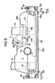
- Figs.9 to 12 show a fourth embodiment of the present invention.
- a guard member 32 3 having a basic shape similar to that of the guard member 32 2 in the third embodiment is used.
- the guard member 32 3 is comprised of support plates 57 fastened to opposite sided ends of the guard plate 56.
- the guard plate 56 is formed similar to the guard plate portion 32a 2 of the guard member 32 2 provided in the third embodiment, but engagement collar portions 56a are integrally provided at vertical opposite ends of the guard plate 56 to protrude toward the fuel tank T 1 .
- the support plate 57 is formed to have a shape similar to those of the support plate portion 32b 2 and the support collar portion 32c 2 of the guard member 32 2 provided in the third embodiment.
- An abutment step 55 is provided on the support plate 57 to abut against the vertical pipe portion 12b, and a nut 33 or a bolt for fastening the support plate 57 to the flange 34 of the fuel tank T 1 is welded to the support plate 57.
- a portion of the support plate 57 is superposed on the side end of the guard plate 56 with its vertical opposite ends engaged with the engagement collar portions 56a of the guard plate 56.
- a pair of limiting projections 57a are integrally formed on the support plate 57a by cutting and rising, and the side end of the guard plate 56 is brought into abutment against the limiting projections 57a.
- Threaded bores 59 are provided at a plurality of points, e.g., two points vertically spaced apart from each other in opposite sides of the guard plate 56, and threaded members 58 are inserted through insertion bore 60 provided in the support plate 57 in correspondence to the threaded bore 59.
- the support plate 57 is fastened to the guard plate 56 by threaded fitting of the threaded member 58 into the threaded bores 59.
- the guard plate 56 and the support plates 57 are previously separated, and the abutment steps 55 of the support plate 57 are welded to the vertical pipe portions 12b, respectively. Therefore, the securing of the guard member 32 3 to the frame F may be carried out using the support plates 57 which have been separated from the guard plate 56 and which are relatively small in size and light in weight. Thus, the workability of welding is enhanced.
- the guard plate 56 may be fastened to the support plates 57.
- the vertical opposite ends of the support plates 57 are brought into engagement with the engagement collar portions 56a of the guard plate 56, whereby even if an operator releases his hand from the guard plate 56, the guard plate 56 can be retained between the support plates 57.
- the lateral movement of the guard plate 56 is limited by the limiting projections 57a of the support plates 57 and hence, the operation of fastening of the guard plate 56 to the support plates 57 can be easily and efficiently carried out.
- the thickness of the guard plate 56 and the thickness of the support plates 57 can be set independently from each other.
- any of the coating color can be selected, leading an increased degree of freedom in design.
- the fuel tank T 1 , T 2 has been disposed below the intake device in each of the embodiments, but the fuel tank may be disposed below the exhaust device 18.
Description
- The present invention relates to an engine generator comprising an engine including an intake device and an exhaust device which are connected to an engine body, a generator connected to the engine, and a fuel tank for supplying fuel to the engine, wherein the engine, the generator and the fuel tank are mounted on a frame.
- Such an engine generator is already known, for example, from Japanese Utility Model Application Laid-open No.5-11367 and the like. In the known structure, an engine body is mounted on a frame with its cylinder axis disposed horizontally, and a fuel tank is mounted to the frame at an upper location in which it covers the engine and generator.
- When a vertical engine with the cylinder axis of an engine body extending vertically is used in the engine generator, the intake device and the exhaust device connected to the engine body are disposed to protrude sideways from the engine body. Therefore, if the fuel tank is disposed above the engine and the generator as in the known engine generator, a wasteful space is produced below the exhaust or intake device within the frame. This is undesirable for providing reductions in size, weight and cost of the engine generator.
- FR-A-4 818 64 A discloses an engine generator which comprises an engine including an intake device and an exhaust device which are connected to an engine body having a vertical cylinder axis extending therefrom, a generator connected to a crankshaft of said engine so as to extend in an axial direction of said crankshaft and a fuel tank for supplying fuel to said engine, wherein said fuel tank is located sideways of the engine but supported by the cylinder head of the engine generator.
- Accordingly, it is an object of the present invention to provide an engine generator wherein when a vertical engine is used, the fuel tank is disposed, so as to avoid the production of a wasteful space, which can contribute to reductions in size, weight and cost.
- In order to achieve the above mentioned object, the present invention proposes according to a first aspect and feature an engine generator according to claim 1.
- With such arrangement, the fuel tank is disposed in a space produced sideways of the engine body below the intake device or the exhaust device. Thus, a wasteful space can be prevented from being produced within the frame, thereby providing reductions in size, weight and cost of the engine generator.
- According to a second aspect and feature of the present invention, in addition to the first feature, a guard member is secured to the frame to cover a side of the fuel tank on the opposite side from the engine body and the generator, and the fuel tank is fixedly supported on the guard member. With such arrangement, the fuel tank is supported by the guard member for protecting the fuel tank, and hence, an exclusive part for supporting the fuel tank is not required, which can contribute to a reduction in number of parts.
- According to a third aspect and feature of the present invention, in addition to the second feature, an elastomeric member for receiving a bottom of the fuel tank is attached to the frame. With such arrangement, even if the frame is vibrated with the operation of the engine and the generator, the vibration cannot be transmitted to the fuel tank, and the weight of the fuel tank can be supported.
- According to a fourth aspect and feature of the present invention, in addition to the second feature, a control panel having a plug socket for taking out an electric power from the generator is mounted on the guard member. With such arrangement, an exclusive control panel is not required, which can contribute to a reduction in number of parts.
- Further, according to a fifth aspect and feature of the present invention, in addition to the first feature, a pipe line for guiding fuel is connected to a bottom of the fuel tank, and a lower guard plate is secured to cover a connected portion of the pipe line to the fuel tank from below. With such arrangement, the connected portion can be protected, so that when the frame is placed on a floor surface, a projection from the floor surface does not strike against the connected portion.
- The above and other objects, features and advantages of the invention will become apparent from the following description of the preferred embodiments taken in conjunction with the accompanying drawings.
-
- Figs.1 to 5 show a first embodiment of the present invention, wherein
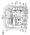
- Fig.1 is a front view of an engine generator;
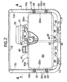
- Fig.2 is a side view taken in a direction of an
arrow 2 in Fig.1; - Fig.3 is a plan view taken in a direction of an arrow 3 in Fig.1;
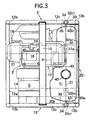
- Fig.4 is a cross-sectional plan view taken along a line 4-4 in Fig.2;
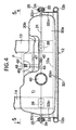
- Fig.5 is a sectional view taken along a line 5-5 in Fig.4;
- Figs.6 and 7 show a second embodiment of the present invention, wherein
- Fig.6 is a side view of an engine generator, similar to Fig.2, but according to the second embodiment;
- Fig.7 is a cross-sectional plan view taken along a line 7-7 in Fig.6;
- Fig.8 is a cross-sectional plan view similar to Fig.7, but according to a third embodiment;
- Figs.9 to 12 show a fourth embodiment of the present invention, wherein
- Fig.9 is a cross-sectional plan view similar to Fig.8, but according to the fourth embodiment;
- Fig.10 is a view taken in a direction of an
arrow 10 in Fig.9; - Fig.11 is an enlarged sectional view taken along a line 11-11 in Fig.10; and
- Fig.12 is an enlarged sectional view taken along a line 12-12 in Fig.10.
-
- The present invention will now be described by way of embodiments with reference to the accompanying drawings.
- Figs.1 to 5 show a first embodiment of the present invention. Referring first to Figs.1 to 3, this transportable-type engine generator comprises an engine E, a generator G and an fuel tank T1 which are mounted on a frame F. The frame F is comprised of a
frame body 12 made by bending a rounded pipe, a pair of lowercross frame elements frame body 12, and an uppercross frame element 15 secured to an upper portion of theframe body 12. - The
frame body 12 includes a pair of lowerside pipe portions 12a extending parallel to each other, fourvertical pipe portions 12b risen upwards from opposite ends of the lowerside pipe portions 12a, and a pair of upperside pipe portions 12c extending perpendicular to a direction of extension of the lowerside pipe portions 12a and connecting upper ends of the pair ofvertical pipe portions 12b to each other. Thecross frame elements cross frame elements side pipe portions 12a of theframe body 12, and the uppercross frame element 15 is mounted to extend between the upperside pipe portions 12c of theframe body 12. - The engine E comprises an
engine body 16 having a cylinder axis disposed vertically, anintake device 17 having acarburetor 19 and anair cleaner 20, and anexhaust device 18 having amuffler 21. Theintake device 17 is connected to an upper portion of theengine body 16 to protrude in one of sideways directions from the upper portion of theengine body 16, and theexhaust device 18 is connected to the upper portion of theengine body 16 to protrude in the other sideways direction from the upper portion of theengine body 16. - The
engine body 16 is mounted on one of the lowercross frame elements 13 with a pair of rubber mount means 22 interposed therebetween. The generator G connected to a crankshaft (not shown) of theengine body 16 is disposed at a location adjacent theengine body 16 to extend in an axial direction of the crankshaft and is mounted on the other lowercross frame element 14 with a rubber mount means 23 interposed therebetween. - A
control panel 28 is attached to an end surface of the generator G opposite from theengine body 16, andplug sockets switch 26 and an indicatinglamp 27 and the like are disposed on thecontrol panel 28. - Referring also to Figs.4 and 5, the fuel tank T1 is formed by thermally depositing a pair of
halves face 31. The fuel tank T1 is disposed sideways of theengine body 16 and the generator G below theintake device 17 in the engine E. - A guard member 321 is secured by welding to the pair of
vertical pipe portions 12b in theframe body 12 of the frame F to cover the side of the fuel tank T1 on the opposite side from theengine body 16 and the generator G. - The guard member 321 is integrally provided with a flat plate-like guard plate portion 32a1 extending between the pair of
vertical pipe portions 12b, a pair of support plate portions 32b1 connected vertically to opposite ends of the guard plate portion 32a1, and a pair of support collar portions 32c1 connected vertically to tip ends of the support plate portions 32b1 and extending outwards. A pair of nut or bolts are welded to connect to each of the support collar portions 32c1. - Such guard member 321 is secured to the
frame body 12, i.e. to the frame F in such a manner that the support plate portions 32b1 inserted into between both of thevertical pipe portions 12b are welded to thevertical pipe portions 12b, respectively. In a state in which the guard member 321 has been secured to the frame F, the support collar portions 32c1 are disposed at locations opposed to thevertical pipe portions 12b from inward. - On the other hand, the fuel tank T1 is integrally provided at its opposite sides with
flanges 34 opposed respectively to the support collar portions 32c1 of the guard member 321. Theflanges 34 are fastened to the support collar portions 32c1 by tighteningbolts 35 threadedly fitted in thenuts 33. Thus, the fuel tank T1 is fixedly supported by the guard member 321 secured to the frame F. Insertion bores provided in theflanges 34 for a deviation in insertion of thebolts 35 are formed in such a large size as to permit the location of the bolts from thenuts 33 within a preset range. - The fuel tank T1 is integrally provided at its bottom with
legs cross frame elements Elastomeric members cross frame elements legs elastomeric members - In this manner, the fuel tank T1 is fixedly supported on the frame F in such a manner that it is disposed sideways of the
engine body 16 and the generator G below theintake device 17 in the engine E. Afuel injection pipe 41 is integrally provided at a location facing upwards without being not covered with theintake device 17 in the upper portion of the fuel tank T1, in such a manner that an opening at the upper end is closed by adetachable cap 40. - A
fuel outlet pipe 42 leading to the inside of the fuel tank T1 is secured to one of thelegs 36 at the bottom of the fuel tank T1, and apipe line 43 having a flexibility such as a rubber hose is connected at its one end to thefuel outlet pipe 42 by aclip 44. - Moreover, a
lower guard plate 45 is welded to the lowercross frame element 13 to which theelastomeric member 38 receiving theleg 36 is attached and to one of the lowerside pipe portion 12a to cover the connected portion of thepipe line 43 to thefuel outlet pipe 42 from below. - On the other hand, a fuel pump P for supplying fuel to the
carburetor 19 of the engine E is disposed between the upper portion of the fuel tank T1 and theengine body 16 and fixedly supported on a stay 46 (see Fig.2) secured to theengine body 16. A recess 47 (see Fig.4) for accommodating a portion of the fuel pump P is provided in an upper portion of the side of the fuel tank T1 which is adjacent theengine body 16. - The
pipe line 43 connected at its one end to thefuel outlet pipe 42 at the bottom of the fuel tank T1 is provided to extend along the side of the fuel tank T1 adjacent theengine body 16 up to the fuel pump P lying thereabove. Afitting groove 48, into which thepipe line 43 is resiliently fitted, is provided in the side of the fuel tank T1 adjacent theengine body 16 to extend vertically, and a first retaining claw 491 and a second retaining claw 492 are also integrally provided on the side of the fuel tank T1 adjacent theengine body 16. The first retaining claw 491 is connected to one of opening end edges of thefitting groove 48, and the second retaining claw 492 is connected to the other opening end edge of thefitting groove 48. The first and second retaining claws 491 and 492 are disposed at locations deviated from each other in a lengthwise direction of thefitting groove 48 in order to simplify a forming die for thefitting groove 48 formed simultaneously with the formation of the half 302 of the fuel tank T1 and to facilitate drawing of the die. - The operation of the first embodiment will be described below. The
intake device 17 is connected to the upper portion of theengine body 16 having the cylinder axis disposed vertically, so as to protrude sideways from theengine body 16, and the fuel tank T1 is fixed to the frame F in such a manner that it is disposed sideways of theengine body 16 and the generator G below theintake device 17. Therefore, the fuel tank T1 is effectively disposed in a space produced sideways of theengine body 16 below theintake device 17. Thus, it is possible to prevent a wasteful space from being produced within the frame F, thereby providing reductions in size, weight and cost of the engine generator. - The guard member 321 is secured to the frame F to cover the side of the fuel tank T1 on the opposite side from the
engine body 16 and the generator G, and the fuel tank T1 is fixedly supported to the guard member 321. Therefore, an exclusive part for supporting the fuel tank is not required, which can contribute to a reduction in number of parts. - Further, the
elastomeric members cross frame elements - The connected portion of the
pipe line 43 to the fuel tank T1 is covered from below with thelower guard plate 45 secured to thecross frame element 13 and the lowerside pipe portion 12a. Therefore, the connected portion can be protected, so that when the engine generator is placed on a floor surface, the projection from the floor surface does not strike against the connected portion of thepipe line 43 to the fuel tank T1. - Further, the
pipe line 43 for feeding the fuel from the fuel tank T1 to the fuel pump P is resiliently fitted in thefitting groove 48 provided in the side of the fuel tank T1, and the fitted state of thepipe line 43 in thefitting groove 48 is retained by the first and second retaining claws 491 and 492 connected to the opening end edges of thefitting groove 48. Therefore, a part for fixing thepipe line 43 is not required other than the fuel tank T1, which enables a reduction in number of parts. - Figs.6 and 7 show a second embodiment of the present invention.
- A
control box 51 is attached to a back surface of a guard plate portion 32a1 of a guard member 321 by a plurality of threadedmembers 52. The guard plate portion 32a1 functions at its area corresponding to thecontrol box 51 as a control panel 28'.Plug sockets lamp 27 and the like are disposed in the control panel 28'. - Moreover, a recess 53 for accommodating a portion of the
control box 51 is provided on a fuel tank T2 having a side covered with the guard member 321. - With the second embodiment, by the fact that the control panel 28' having the
plug sockets control panel 28 to the generator G and the like as in the first embodiment. This can contribute to a reduction in number of parts and a compactness of the engine generator. - Fig.8 shows a third embodiment of the present invention. A guard member 322 covering a side of a fuel tank T1 is integrally provided with a flat plate-like guard plate portion 32a2, a pair of support plate portions 32b2 connected to opposite ends of the guard plate portions 32a2 and having
abutment steps 55 which are abutable against thevertical pipe portions 12b of theframe body 12 from inward, and a pair of support collar portions 32c2 connected vertically to tip ends of the support plate portions 32b2 and extending outwards. A pair ofnuts 33 or bolts for fastening theflanges 34 of the fuel tank T1 are welded to each of the support collar portions 32c2. - Moreover, the length L1 between opposite side ends of the guard plate portions 32a2 is set smaller than a distance L2 between the
vertical pipe portions 12b (L1 < L2), and the abutment steps 55 are welded to thevertical pipe portions 12b. - In the first and second embodiments, the support plate portions 32b1 of the guard member 321 are inserted into between both the
vertical pipe portions 12b and welded to thevertical pipe portions 12b and hence, it is necessary to accurately determine the length between the opposite side ends of the guard plate portions 32a1 corresponding to the distance L2 between thevertical pipe portions 12b. With the third embodiment, however, even if the length L1 between the opposite side ends of the guard plate portion 32a2 is set relatively roughly, the abutment steps 55 can be brought into abutment against and welded to thevertical pipe portions 12b, leading to an easy dimensional control. - Figs.9 to 12 show a fourth embodiment of the present invention.
- In this engine generator, a guard member 323 having a basic shape similar to that of the guard member 322 in the third embodiment is used. The guard member 323 is comprised of
support plates 57 fastened to opposite sided ends of theguard plate 56. - The
guard plate 56 is formed similar to the guard plate portion 32a2 of the guard member 322 provided in the third embodiment, butengagement collar portions 56a are integrally provided at vertical opposite ends of theguard plate 56 to protrude toward the fuel tank T1. Thesupport plate 57 is formed to have a shape similar to those of the support plate portion 32b2 and the support collar portion 32c2 of the guard member 322 provided in the third embodiment. Anabutment step 55 is provided on thesupport plate 57 to abut against thevertical pipe portion 12b, and anut 33 or a bolt for fastening thesupport plate 57 to theflange 34 of the fuel tank T1 is welded to thesupport plate 57. - A portion of the
support plate 57 is superposed on the side end of theguard plate 56 with its vertical opposite ends engaged with theengagement collar portions 56a of theguard plate 56. A pair of limitingprojections 57a are integrally formed on thesupport plate 57a by cutting and rising, and the side end of theguard plate 56 is brought into abutment against the limitingprojections 57a. - Threaded bores 59 are provided at a plurality of points, e.g., two points vertically spaced apart from each other in opposite sides of the
guard plate 56, and threadedmembers 58 are inserted through insertion bore 60 provided in thesupport plate 57 in correspondence to the threaded bore 59. Thus, thesupport plate 57 is fastened to theguard plate 56 by threaded fitting of the threadedmember 58 into the threaded bores 59. - In securing the guard member 323 to the frame F, the
guard plate 56 and thesupport plates 57 are previously separated, and the abutment steps 55 of thesupport plate 57 are welded to thevertical pipe portions 12b, respectively. Therefore, the securing of the guard member 323 to the frame F may be carried out using thesupport plates 57 which have been separated from theguard plate 56 and which are relatively small in size and light in weight. Thus, the workability of welding is enhanced. - After securing of the
support plates 57 to thevertical pipe portions 12b, theguard plate 56 may be fastened to thesupport plates 57. During this fastening, the vertical opposite ends of thesupport plates 57 are brought into engagement with theengagement collar portions 56a of theguard plate 56, whereby even if an operator releases his hand from theguard plate 56, theguard plate 56 can be retained between thesupport plates 57. In addition, the lateral movement of theguard plate 56 is limited by the limitingprojections 57a of thesupport plates 57 and hence, the operation of fastening of theguard plate 56 to thesupport plates 57 can be easily and efficiently carried out. - Since the
guard plate 56 and thesupport plates 57 are capable of being separated from each other in the above manner, the thickness of theguard plate 56 and the thickness of thesupport plates 57 can be set independently from each other. In addition, by preparing a plurality of theguard plates 56 having different coating colors, any of the coating color can be selected, leading an increased degree of freedom in design. - Although the embodiments of the present invention has been described in detail, it will be understood that the present invention is not limited to the above-described embodiments, and various modifications may be made without departing from the spirit and scope of the invention defined in claims.
- For example, the fuel tank T1, T2 has been disposed below the intake device in each of the embodiments, but the fuel tank may be disposed below the
exhaust device 18.
Claims (5)
- An engine generator comprising an engine (E) including an intake device (17) and an exhaust device (18) which are connected to an engine body (16) having a vertical cylinder axis extending therefrom, a generator (G) connected to a crankshaft of said engine (E) so as to extend in an axial direction of said crankshaft, and a fuel tank (T1, T2) for supplying fuel to said engine (E), wherein said engine body (16) is disposed sideways along said fuel tank (T1, T2), said engine (E), said generator (G) and said fuel tank (T1, T2) are mounted on a frame (F), said engine (E) and said generator (G) are supported on a bottom (13, 14) of said frame (F) and both said engine body (16) and said generator (G) are disposed sideways along said fuel tank (T1, T2),
characterized in that said intake device (17) and said exhaust device (18) are connected to an upper portion of said engine body (16) to protrude sideways and to opposite sides from said engine body (16), and that said fuel tank (T1, T2) is located below said intake device (17) or said exhaust device (18), and is supported on said bottom (13, 14) of the frame (F) separately from said engine (E) and said generator (G). - An engine generator according to claim 1, further including a guard member (321, 322, 323) which is secured to said frame to cover a side of said fuel tank (T1, T2) on the opposite side from said engine body (16) and said generator (G), said fuel tank being fixedly supported on said guard member (321, 322, 323).
- An engine generator according to claim 2, further including an elastomeric member (38, 39) attached to the bottom (13, 14) of said frame (F) for receiving a bottom of said fuel tank (T1, T2).
- An engine generator according to claim 2, further including a control panel (28') having a plug socket (24, 25) for taking out an electric power from said generator (G), said control panel (28') being mounted on said guard member (321).
- An engine generator according to claim 1, further including a pipe line (44) connected to a bottom of said fuel tank (T1, T2) for guiding fuel, and a lower guard plate (45) secured to cover a connected portion of said pipe line (44) to said fuel tank (T1, T2) from below.
Applications Claiming Priority (3)
| Application Number | Priority Date | Filing Date | Title |
|---|---|---|---|
| JP243584/97 | 1997-09-09 | ||
| JP24358497 | 1997-09-09 | ||
| JP24358497A JP3954700B2 (en) | 1997-09-09 | 1997-09-09 | Motor generator |
Publications (3)
| Publication Number | Publication Date |
|---|---|
| EP0902178A2 EP0902178A2 (en) | 1999-03-17 |
| EP0902178A3 EP0902178A3 (en) | 1999-12-29 |
| EP0902178B1 true EP0902178B1 (en) | 2003-10-22 |
Family
ID=17105999
Family Applications (1)
| Application Number | Title | Priority Date | Filing Date |
|---|---|---|---|
| EP98116813A Expired - Lifetime EP0902178B1 (en) | 1997-09-09 | 1998-09-04 | Engine generator |
Country Status (5)
| Country | Link |
|---|---|
| US (1) | US6067945A (en) |
| EP (1) | EP0902178B1 (en) |
| JP (1) | JP3954700B2 (en) |
| CN (1) | CN1081734C (en) |
| DE (1) | DE69819095T2 (en) |
Families Citing this family (20)
| Publication number | Priority date | Publication date | Assignee | Title |
|---|---|---|---|---|
| WO1999005771A1 (en) * | 1997-07-23 | 1999-02-04 | Brighton Barry David | An electrical power generation unit |
| DE69927789T2 (en) * | 1999-05-31 | 2006-07-06 | Nortron Aps | Compact apparatus and method for generating power |
| WO2002066196A1 (en) | 2001-02-20 | 2002-08-29 | Deon John Du Plessis | An electrical power generation unit |
| US6376951B1 (en) | 2001-05-14 | 2002-04-23 | Tampa Armature Works, Inc. | Cover for marine generators |
| US6801425B2 (en) * | 2001-06-04 | 2004-10-05 | Black & Decker Inc. | Ergonomic control panel for a portable electric generator |
| US6630756B2 (en) * | 2001-07-12 | 2003-10-07 | Generac Power Systems, Inc. | Air flow arrangement for generator enclosure |
| US6750556B2 (en) * | 2002-03-26 | 2004-06-15 | Briggs & Stratton Power Products Group, Llc | Removable fuel tank |
| JP4246147B2 (en) * | 2002-07-01 | 2009-04-02 | 本田技研工業株式会社 | Internal combustion engine drive working machine |
| JP4142376B2 (en) * | 2002-09-10 | 2008-09-03 | 本田技研工業株式会社 | Motorcycle fuel tank mounting structure |
| CN1748347A (en) * | 2003-02-10 | 2006-03-15 | 布里格斯-斯特拉顿动力产品集团公司 | Monitoring system for a generator |
| US20040168653A1 (en) * | 2003-02-28 | 2004-09-02 | Radtke David E. | Fuel tank design for engine-driven generator |
| US6952056B2 (en) * | 2003-08-06 | 2005-10-04 | Briggs & Stratton Power Products Group, Llc | Generator including vertically shafted engine |
| WO2005093236A1 (en) * | 2004-03-29 | 2005-10-06 | Gerhard Auer | Mobile power plant |
| US7314397B2 (en) | 2005-05-13 | 2008-01-01 | Briggs & Stratton Corporation | Standby generator |
| MY144502A (en) * | 2005-06-23 | 2011-09-30 | Honda Motor Co Ltd | Multipurpose engine |
| JP4512080B2 (en) | 2006-11-10 | 2010-07-28 | トヨタ自動車株式会社 | Exhaust gas purification device for internal combustion engine |
| CA2668522C (en) * | 2008-06-27 | 2017-07-04 | Honda Motor Co., Ltd. | Engine generator |
| JP5697698B2 (en) | 2013-03-05 | 2015-04-08 | 富士重工業株式会社 | Engine mount structure for engine-equipped equipment |
| USD749511S1 (en) | 2013-07-10 | 2016-02-16 | Champion Power Equipment, Inc. | Engine powered generator |
| JP2017166400A (en) * | 2016-03-16 | 2017-09-21 | 本田技研工業株式会社 | Engine drive work machine |
Family Cites Families (14)
| Publication number | Priority date | Publication date | Assignee | Title |
|---|---|---|---|---|
| US1396418A (en) * | 1921-11-08 | gilliard | ||
| FR481864A (en) * | 1915-10-27 | 1917-01-24 | Charles Franklin Kettering | Improvements to the power generation system |
| US1526988A (en) * | 1920-07-19 | 1925-02-17 | Delcolight Company | Power plant |
| US1573883A (en) * | 1921-06-02 | 1926-02-23 | Merritt A Vining | Dynamo-electric plant |
| US3046899A (en) * | 1959-08-14 | 1962-07-31 | Rockwell Gmbh | Generator or pump assembly |
| GB1587696A (en) * | 1977-07-29 | 1981-04-08 | Fiat Spa | Self-contained unit for the combined production of electrical energy and heat |
| JPS6081426A (en) * | 1983-10-13 | 1985-05-09 | Yanmar Diesel Engine Co Ltd | Work machine driven by internal-combustion engine |
| JPH03281937A (en) * | 1990-03-30 | 1991-12-12 | Kubota Corp | Engine working machine |
| JP3042020B2 (en) * | 1991-04-30 | 2000-05-15 | スズキ株式会社 | Soundproof welding machine |
| JPH0511367A (en) * | 1991-07-04 | 1993-01-22 | Matsushita Electric Ind Co Ltd | Copying device provided with automatic page changer function |
| DE59207721D1 (en) * | 1991-12-12 | 1997-01-30 | New Sulzer Diesel Ag | Stationary system with reciprocating piston internal combustion engine and turbocharging |
| US5624589A (en) * | 1995-09-11 | 1997-04-29 | Illinois Tool Works Inc. | Segregated cooling air flow for engine driven welder |
| DE29610022U1 (en) * | 1996-06-07 | 1996-08-29 | Spies Robert | Stand and support frame for a power generator |
| US5928535A (en) * | 1997-05-08 | 1999-07-27 | Miller Electric Manufacturing Co. | Fuel tank filler assembly for engine driven welder |
-
1997
- 1997-09-09 JP JP24358497A patent/JP3954700B2/en not_active Expired - Fee Related
-
1998
- 1998-09-01 US US09/145,412 patent/US6067945A/en not_active Expired - Lifetime
- 1998-09-04 EP EP98116813A patent/EP0902178B1/en not_active Expired - Lifetime
- 1998-09-04 DE DE69819095T patent/DE69819095T2/en not_active Expired - Fee Related
- 1998-09-09 CN CN98119117A patent/CN1081734C/en not_active Expired - Fee Related
Also Published As
| Publication number | Publication date |
|---|---|
| CN1081734C (en) | 2002-03-27 |
| EP0902178A3 (en) | 1999-12-29 |
| JP3954700B2 (en) | 2007-08-08 |
| US6067945A (en) | 2000-05-30 |
| CN1210939A (en) | 1999-03-17 |
| DE69819095T2 (en) | 2004-08-12 |
| JPH1182043A (en) | 1999-03-26 |
| DE69819095D1 (en) | 2003-11-27 |
| EP0902178A2 (en) | 1999-03-17 |
Similar Documents
| Publication | Publication Date | Title |
|---|---|---|
| EP0902178B1 (en) | Engine generator | |
| JPH0533720Y2 (en) | ||
| JPH07309275A (en) | Part installation structure for motorcycle | |
| US6725905B2 (en) | Radiator unit for engine and method of combining the same with engine | |
| JP3871124B2 (en) | Protective frame type internal combustion engine working machine | |
| JP4412003B2 (en) | Engine cover mounting structure | |
| JPH0811558A (en) | Vibration isolator of traveling farm working machinery | |
| US4744411A (en) | Mounting arrangement of an intercooler | |
| JP3663900B2 (en) | Engine suspension system for motorcycles | |
| JP4246147B2 (en) | Internal combustion engine drive working machine | |
| JP3731687B2 (en) | Protective frame type internal combustion engine working machine | |
| JP2017078352A (en) | Engine accessory support structure | |
| KR100652520B1 (en) | Air cleaner supporting structure in a v-type engine | |
| JPH1182044A (en) | Engine generator | |
| US7104256B2 (en) | Throttle body fixing structure | |
| JPH0529991Y2 (en) | ||
| JPS6312075Y2 (en) | ||
| JPS59301Y2 (en) | Motorcycle fuel tank mounting structure | |
| JPH0746869Y2 (en) | Mounting device for engine generator | |
| JPS6233076Y2 (en) | ||
| JP3015331B2 (en) | Engine cover | |
| JPH0717791Y2 (en) | Engine and mission coupling reinforcement device | |
| JPH0443379Y2 (en) | ||
| JPH0640506Y2 (en) | Air cleaner mounting structure for walk-behind cultivator | |
| JPS63154820A (en) | Electrical equipment parts storage device for engine |
Legal Events
| Date | Code | Title | Description |
|---|---|---|---|
| PUAI | Public reference made under article 153(3) epc to a published international application that has entered the european phase |
Free format text: ORIGINAL CODE: 0009012 |
|
| AK | Designated contracting states |
Kind code of ref document: A2 Designated state(s): DE FR GB IT |
|
| AX | Request for extension of the european patent |
Free format text: AL;LT;LV;MK;RO;SI |
|
| PUAL | Search report despatched |
Free format text: ORIGINAL CODE: 0009013 |
|
| AK | Designated contracting states |
Kind code of ref document: A3 Designated state(s): AT BE CH CY DE DK ES FI FR GB GR IE IT LI LU MC NL PT SE |
|
| AX | Request for extension of the european patent |
Free format text: AL;LT;LV;MK;RO;SI |
|
| 17P | Request for examination filed |
Effective date: 20000309 |
|
| AKX | Designation fees paid |
Free format text: DE FR GB IT |
|
| 17Q | First examination report despatched |
Effective date: 20020114 |
|
| GRAH | Despatch of communication of intention to grant a patent |
Free format text: ORIGINAL CODE: EPIDOS IGRA |
|
| GRAS | Grant fee paid |
Free format text: ORIGINAL CODE: EPIDOSNIGR3 |
|
| GRAA | (expected) grant |
Free format text: ORIGINAL CODE: 0009210 |
|
| AK | Designated contracting states |
Kind code of ref document: B1 Designated state(s): DE FR GB IT |
|
| REG | Reference to a national code |
Ref country code: GB Ref legal event code: FG4D |
|
| REF | Corresponds to: |
Ref document number: 69819095 Country of ref document: DE Date of ref document: 20031127 Kind code of ref document: P |
|
| ET | Fr: translation filed | ||
| PLBE | No opposition filed within time limit |
Free format text: ORIGINAL CODE: 0009261 |
|
| STAA | Information on the status of an ep patent application or granted ep patent |
Free format text: STATUS: NO OPPOSITION FILED WITHIN TIME LIMIT |
|
| 26N | No opposition filed |
Effective date: 20040723 |
|
| PGFP | Annual fee paid to national office [announced via postgrant information from national office to epo] |
Ref country code: DE Payment date: 20070629 Year of fee payment: 10 |
|
| PGFP | Annual fee paid to national office [announced via postgrant information from national office to epo] |
Ref country code: GB Payment date: 20070821 Year of fee payment: 10 |
|
| PGFP | Annual fee paid to national office [announced via postgrant information from national office to epo] |
Ref country code: IT Payment date: 20070907 Year of fee payment: 10 |
|
| PGFP | Annual fee paid to national office [announced via postgrant information from national office to epo] |
Ref country code: FR Payment date: 20070927 Year of fee payment: 10 |
|
| GBPC | Gb: european patent ceased through non-payment of renewal fee |
Effective date: 20080904 |
|
| REG | Reference to a national code |
Ref country code: FR Ref legal event code: ST Effective date: 20090529 |
|
| PG25 | Lapsed in a contracting state [announced via postgrant information from national office to epo] |
Ref country code: IT Free format text: LAPSE BECAUSE OF NON-PAYMENT OF DUE FEES Effective date: 20080904 Ref country code: DE Free format text: LAPSE BECAUSE OF NON-PAYMENT OF DUE FEES Effective date: 20090401 |
|
| PG25 | Lapsed in a contracting state [announced via postgrant information from national office to epo] |
Ref country code: FR Free format text: LAPSE BECAUSE OF NON-PAYMENT OF DUE FEES Effective date: 20080930 |
|
| PG25 | Lapsed in a contracting state [announced via postgrant information from national office to epo] |
Ref country code: GB Free format text: LAPSE BECAUSE OF NON-PAYMENT OF DUE FEES Effective date: 20080904 |