EP0900941B1 - Vorrichtung zur Unterstützung der Motoreinheit eines Ventilators - Google Patents
Vorrichtung zur Unterstützung der Motoreinheit eines Ventilators Download PDFInfo
- Publication number
- EP0900941B1 EP0900941B1 EP98116329A EP98116329A EP0900941B1 EP 0900941 B1 EP0900941 B1 EP 0900941B1 EP 98116329 A EP98116329 A EP 98116329A EP 98116329 A EP98116329 A EP 98116329A EP 0900941 B1 EP0900941 B1 EP 0900941B1
- Authority
- EP
- European Patent Office
- Prior art keywords
- grille
- head
- vibration
- openings
- flaps
- Prior art date
- Legal status (The legal status is an assumption and is not a legal conclusion. Google has not performed a legal analysis and makes no representation as to the accuracy of the status listed.)
- Expired - Lifetime
Links
- 238000013016 damping Methods 0.000 claims description 27
- 230000002093 peripheral effect Effects 0.000 claims description 6
- 230000008878 coupling Effects 0.000 claims description 4
- 238000010168 coupling process Methods 0.000 claims description 4
- 238000005859 coupling reaction Methods 0.000 claims description 4
- 239000013013 elastic material Substances 0.000 claims description 2
- 230000037431 insertion Effects 0.000 claims description 2
- 238000003780 insertion Methods 0.000 claims description 2
- 238000001914 filtration Methods 0.000 description 4
- 239000000463 material Substances 0.000 description 4
- 239000002184 metal Substances 0.000 description 4
- 230000000694 effects Effects 0.000 description 3
- 239000004033 plastic Substances 0.000 description 3
- 229920003023 plastic Polymers 0.000 description 3
- 238000004378 air conditioning Methods 0.000 description 1
- 230000000712 assembly Effects 0.000 description 1
- 238000000429 assembly Methods 0.000 description 1
- 238000005452 bending Methods 0.000 description 1
- 239000003610 charcoal Substances 0.000 description 1
- 230000002950 deficient Effects 0.000 description 1
- 239000004519 grease Substances 0.000 description 1
- 230000000670 limiting effect Effects 0.000 description 1
- 239000002245 particle Substances 0.000 description 1
- 238000007789 sealing Methods 0.000 description 1
- 125000006850 spacer group Chemical group 0.000 description 1
Images



Classifications
-
- F—MECHANICAL ENGINEERING; LIGHTING; HEATING; WEAPONS; BLASTING
- F04—POSITIVE - DISPLACEMENT MACHINES FOR LIQUIDS; PUMPS FOR LIQUIDS OR ELASTIC FLUIDS
- F04D—NON-POSITIVE-DISPLACEMENT PUMPS
- F04D29/00—Details, component parts, or accessories
- F04D29/60—Mounting; Assembling; Disassembling
- F04D29/62—Mounting; Assembling; Disassembling of radial or helico-centrifugal pumps
- F04D29/624—Mounting; Assembling; Disassembling of radial or helico-centrifugal pumps especially adapted for elastic fluid pumps
- F04D29/626—Mounting or removal of fans
-
- F—MECHANICAL ENGINEERING; LIGHTING; HEATING; WEAPONS; BLASTING
- F04—POSITIVE - DISPLACEMENT MACHINES FOR LIQUIDS; PUMPS FOR LIQUIDS OR ELASTIC FLUIDS
- F04D—NON-POSITIVE-DISPLACEMENT PUMPS
- F04D29/00—Details, component parts, or accessories
- F04D29/66—Combating cavitation, whirls, noise, vibration or the like; Balancing
- F04D29/661—Combating cavitation, whirls, noise, vibration or the like; Balancing especially adapted for elastic fluid pumps
- F04D29/668—Combating cavitation, whirls, noise, vibration or the like; Balancing especially adapted for elastic fluid pumps damping or preventing mechanical vibrations
Definitions
- the present invention relates to a device for supporting the motor unit of fans and the like, particularly for filtering suction hoods.
- fans for example of the centrifugal type, which are constituted by an impeller driven by a corresponding motor unit inside a suitable enclosure.
- a conventioal enclosure has a pair of mutually opposite heads between which a jacket, forming a sort of volute, is fastened; these heads are formed by rings of metal plate which are closed by respective grilles, made for example of plastics, one of which supports the motor.
- the aim of the present invention is to solve the above-described problem, providing a device for supporting the motor unit of fans and the like which can absorb any vibrations that might be produced, so as to ensure silent operation.
- an object of the present invention is to provide a device for supporting the motor unit which is simple in concept, safely reliable in operation and versatile in use.
- the present device for supporting the motor unit of fans and the like, of the type comprising a grille which is suitable to be applied in a front region, along a peripheral annular part, to a head of the enclosure of an impeller and forms, in a central region, means for coupling to a motor unit of said impeller, which is supported in a cantilevered manner inside said enclosure, which is characterized in that it comprises a vibration-damping insert made of elastic material which is adapted to be interposed between said grille and said head at said peripheral annular part, and is provided with flaps which protrude transversely through corresponding slots formed in said head; and means for locking said grille to said head which are adapted to be inserted through respective openings formed in said grille, at said slots of said head, and to retain said flaps of said vibration-damping insert on said head so as to wrap around said head in the fastening position by acting from outside.
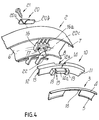
- 1 generally designates the device for supporting the motor unit of fans and the like, particularly for filtering suction hoods.
- the device 1 has a grille 2, particularly made of plastic material, which is adapted to be applied in a front region to a head 3 of the fan enclosure.
- the head 3 is conventionally shaped, by a sheet metal ring which is shaped like a scroll and is surrounded by sides 4 and 5 along the outer and inner edges.
- the grille 2 has a peripheral annular part 6 which is circular and is surrounded by corresponding sides 7 and 8 which are directed toward the head 3, along the outer and inner edges; the grille 2 forms, in a central region, a shaped portion 9 for the coupling of the motor unit of the fan, which is not shown.
- the coupling portion 9 is adapted to rigidly couple a motor having a rectangular profile; however, the grille 2 may of course be provided so as to support motors having a different shape, for example a circular or square one.
- An insert 10 made of a material such as rubber and suitable to damp the vibrations produced by the motor, is suitable to be interposed between the grille 2 and the head 3.
- the vibration-damping insert 10 is constituted by an annular element 11 which has corresponding peripheral edges 12 and 13 which are directed toward the circular annular part 6 of the grille 2 in the assembled position.
- a series of prism-shaped protrusions 14 is formed along the annular element 11 of the vibration-damping insert 10; said protrusions are evenly distributed and are directed toward the head 3 in the assembled position.
- the protrusions 14 delimit corresponding cavities 15 formed at the internal perimeter of the annular element 11 and are suitable to wrap around corresponding raised portions 16 which are prism-shaped, in practice rectangular, and are formed at the rim of respective openings 17 formed in the circular annular part 6 of the grille 2.
- the raised portions 16 are joined to the outer side 7 of the grille 2 by a series of ribs or ridges 16a which are suitable to center the insert 10 and damp vibrations.
- the ridges 16a engage a corresponding cavity 12a formed on the edge 12 of the insert 10 (reference should be made in particular to Figure 6).
- the annular element 11 of the vibration-damping insert 10 covers the entire circumference and has protrusions 14 which are evenly distributed along said circumference.
- the head 3 in turn has, along the internal edge, a corresponding series of slots 18 which are adapted to wrap around respective protrusions 14 of the vibration-damping insert 10.
- said protrusions 14 are clamped, in the assembled position, respectively between the raised portions 16 of the grille 2 and the edge of the slots 18 of the head 3.
- the protrusions 14 further have two transverse notches 19 which are suitable to delimit a median portion 14a of said protrusions which substantially forms a flexible flap.
- the grille 2 is meant to be locked to the head 3 by means of a plurality of step-shaped brackets 20 which are inserted through said openings 17 formed in the grille 2 and are fastened by means of corresponding screws 21 which screw into respective stubs 22 which are formed by said grille 2 along the inner side 8 at said openings 17.
- the brackets 20 are adapted to fold said flaps 14a of the vibration-damping insert 10 onto the head 3, so as to wrap around said head 3 in the clamping position.
- brackets 20 have, at their ends, respective portions 20a and 20b which are folded in a parallel arrangement on opposite sides; the first folded portion 20a has a hole 23 for the insertion of the screw 21, while the second portion 20b is adapted to fold, in the assembled position shown by the dashed lines 20c in figure 4, the flap 14a of the vibration-damping insert 10 onto the opposite head 3.
- the vibration-damping insert 10 is interposed between the grille 2 and the metal plate head 3 of the enclosure, taking care to fit the protrusions 14 on the corresponding raised portions 16 of the grille 2 and to subsequently engage thereon the corresponding slots 18 of the head 3.
- the slots 18 formed on the head 3 also center said head 3 with respect to the grille 2 and prevent their mutual rotation.
- the respective locking brackets 20 are then inserted through the openings 17 of the grille 2 by acting from outside. Said brackets 20 pass through the corresponding cavities 15 of the annular element 11 of the insert 10 and, by means of the folded portion 20b, fold the flaps 14a of said insert 10 against the head 3 (see also Figure 3).
- the locking brackets 20 are then fastened to the grille 2 by means of the screws 21 which screw into the stubs 22.
- the grille 2 that supports the motor is rigidly coupled to the head 3 of the casing by interposing the vibration-damping insert 10 wrapping around said head 3 by means of the flaps 14a folded by the locking brackets 20.
- the vibration-damping insert 10 wrapping around said head 3 by means of the flaps 14a folded by the locking brackets 20.
- the vibration-damping insert 10 acts as a damping element for the vibrations produced by the motor and by the elements connected thereto, particularly the impeller. Said vibration-damping effect also affects axial rotation in the two opposite directions and the radial direction, by virtue of the configuration of the protrusions 14 of the insert 10 wrapping around the slots 18 of the head 3.
- the vibration-damping insert 10 can of course be made of materials having different rigidities according to the weight of the motor, so as to achieve the best damping effect according to the specific requirements.
- Said damping effect can also be adjusted appropriately by means of suitable washers inserted between the folded portion 20a of the locking brackets and the corresponding sleeves 22 so as to act as spacers.
- the insert is accordingly compressed more or less intensely according to the thickness of said washers.
- the outer edge 12 of the insert 10 also acts as a hermetic sealing element if a charcoal filter or the like is applied to the grille 2 to form a filtering hood.
- Figure 5 illustrates a different embodiment of the device, in which the means for locking the grille 2 to the head 3 are constituted by a plate 24 which is provided with a threaded stem 25 whereon a corresponding nut 26 is preassembled.
- the raised portion 16 shaped on the grille 2 forms, in this case, a sort of hollow into which the plate 24 is guided, causing in this case also the bending of the flap 14a of the insert 10 so as to wrap around the head 3, providing a latch-like closure.
- the stem 25 of said plate 24 passes through a slot 27 formed on the bottom of said hollow.
- the flaps 14a of the vibration-damping insert 10 can be provided rigidly in said folded shape adapted to wrap around the head 3.
- the brackets 20 retain said flaps 14a in said fastening position.
- the aim of the present invention is to provide the support of the motor unit of fans and the like so as to damp any vibrations produced and thus ensure silent operation.
- brackets 20 or, as an alternative, the plates 24 can be inserted after assembling the supporting elements of the motor and the corresponding insert in the respective seat.
- the device can be advantageously applied not only to the above-mentioned centrifugal aspirators but also to helical and vane aspirators and more generally to other similar industrial and civil applications and in different fields, such as for example the automotive field, the air-conditioning field and the like.
- the device according to the invention allows to easily lock the support of the motor by way of the locking means earlier described once said motor has been arranged in its seat. Likewise, it is possible to perform release from the outside.
- the device is very sturdy and electrically very safe, when it uses plastics elements, such as said grille, to support the motor, and in particular does not require earthing.
- the materials employed, as well as the shape and the dimensions, may be any according to requirements.
Landscapes
- Engineering & Computer Science (AREA)
- Mechanical Engineering (AREA)
- General Engineering & Computer Science (AREA)
- Structures Of Non-Positive Displacement Pumps (AREA)
Claims (8)
- Vorrichtung zum Halten der Motoreinheit von Lüftern und dergleichen, mit einem Gitter (2), das dazu geeignet ist, in einem vorderen Bereich entlang einem ringförmigen Umfangsteil an einem Kopf (3) des Gehäuses eines Laufrads angebracht zu werden, und in einem mittleren Bereich Mittel (9) zum Koppeln an eine Motoreinheit des Laufrads bildet, die freitragend in dem Gehäuse gehalten ist, dadurch gekennzeichnet, daß sie einen schwingungsdämpfenden Einsatz (10) aus elastischem Material hat, der dazu geeignet ist, zwischen dem Gitter (2) und dem Kopf (3) an dem ringförmigen Umfangsteil angeordnet zu werden, und versehen ist mit Klappen (14a), die in Querrichtung durch entsprechende Schlitze (18) in dem Kopf (3) hindurch ragen, sowie Mitteln (20, 24) zum Befestigen des Gitters (2) an dem Kopf (3), die dazu geeignet sind, an den Schlitzen (18) des Kopfes (3) durch entsprechende Öffnungen (17, 27) in dem Gitter (2) eingeführt zu werden und die Klappen (14a) des schwingungsdämpfenden Einsatzes (10) so an dem Kopf (3) festzuhalten, daß sie sich in der Befestigungsstellung durch Einwirken von außen um den Kopf legen.
- Vorrichtung nach Anspruch 1, dadurch gekennzeichnet, daß der schwingungsdämpfende Einsatz (10) aus einem ringförmigen Element (11) besteht, das entsprechende prismenförmige Vorsprünge (14) hat, die die Klappen (14a) bilden und dazu geeignet sind, entsprechende Hohlräume (15) zu begrenzen, die an den in dem Gitter (2) gebildeten Öffnungen (17, 27) in dem ringförmigen Element (11) ausgebildet sind.
- Vorrichtung nach Anspruch 2, dadurch gekennzeichnet, daß die Vorsprünge (14) des schwingungsdämpfenden Einsatzes (10) dazu geeignet sind, sich um entsprechende prismenförmige erhabene Abschnitte (16), zu legen, die jeweils an der Kante der in dem Gitter (2) gebildeten Öffnungen (17, 27) ausgebildet sind.
- Vorrichtung nach Anspruch 1, dadurch gekennzeichnet, daß die Schlitze (18) des Kopfes (3) in der Befestigungsstellung durch Einsetzen entsprechender Vorsprünge (14) des schwingungsdämpfenden Einsatzes (10) mit entsprechenden prismenförmigen erhabenen Abschnitten (16) in Eingriff treten, die von dem Gitter (2) jeweils an den Öffnungen (17, 27) gebildet sind.
- Vorrichtung nach Anspruch 1, dadurch gekennzeichnet, daß die Mittel zum Befestigen des Gitters (2) an dem Kopf eine Reihe stufenförmiger Klammern (20) haben, die dazu geeignet sind, durch die Öffnungen (17) in dem Gitter (2) derart eingeführt zu werden, daß sie mit den Klappen (14a) des schwingungsdämpfenden Einsatzes (10) in Eingriff kommen, und die durch entsprechende Schrauben (21) befestigt sind, sie sich in jeweilige von dem Gitter (2) gebildete Gewinde (28) schrauben.
- Vorrichtung nach Anspruch 5, dadurch gekennzeichnet, daß die Klammem (20) an ihren Enden jeweilige Abschnitte (20a, 20b) haben, die auf einander abgewandten Seiten in parallele Richtungen gebogen sind und zum Einführen der Schrauben (21) bzw. zum Festhalten der Klappen (14a) des schwingungsdämpfenden Einsatzes (10) auf dem Kopf (3) dienen.
- Vorrichtung nach Anspruch 1, dadurch gekennzeichnet, daß die Mittel zum Befestigen des Gitters an dem Kopf eine Reihe von Platten (24) haben, die jeweils mit einem Gewindeschaft (25) versehen sind, auf dem eine entsprechende Mutter (26) vormontiert ist und der durch die Öffnungen (27) in dem Gitter (2) verläuft, wobei die Platten (24) dazu geeignet sind, in einem entsprechenden erhabenen Abschnitt (16), der an dem Gitter (2) an den Öffnungen (27) geformt ist, derart geführt zu werden, daß sie mit den Klappen (14a) des schwingungsdämpfenden Einsatzes (10) in Eingriff treten.
- Vorrichtung nach Anspruch 1, dadurch gekennzeichnet, daß der schwingungsdämpfende Einsatz (10) aus einer Reihe von ringförmigen Elementen (11) besteht, die jeweils mit prismenförmigen Vorsprüngen (14) versehen sind, die die Klappen (14a) bilden und dazu geeignet sind, entsprechende Hohlräume (15) zu begrenzen, die an den in dem Gitter (2) gebildeten Öffnungen (17, 27) an dem ringförmigen Element (11) ausgebildet sind.
Applications Claiming Priority (2)
| Application Number | Priority Date | Filing Date | Title |
|---|---|---|---|
| ITBO970526 | 1997-09-03 | ||
| IT97BO000526A IT1294180B1 (it) | 1997-09-03 | 1997-09-03 | Dispositivo per il supporto dell'organo motore di ventilatori e simili |
Publications (3)
| Publication Number | Publication Date |
|---|---|
| EP0900941A2 EP0900941A2 (de) | 1999-03-10 |
| EP0900941A3 EP0900941A3 (de) | 1999-12-08 |
| EP0900941B1 true EP0900941B1 (de) | 2003-07-09 |
Family
ID=11342500
Family Applications (1)
| Application Number | Title | Priority Date | Filing Date |
|---|---|---|---|
| EP98116329A Expired - Lifetime EP0900941B1 (de) | 1997-09-03 | 1998-08-28 | Vorrichtung zur Unterstützung der Motoreinheit eines Ventilators |
Country Status (3)
| Country | Link |
|---|---|
| EP (1) | EP0900941B1 (de) |
| DE (1) | DE69816204T2 (de) |
| IT (1) | IT1294180B1 (de) |
Families Citing this family (4)
| Publication number | Priority date | Publication date | Assignee | Title |
|---|---|---|---|---|
| JP2001309601A (ja) * | 2000-04-25 | 2001-11-02 | Asmo Co Ltd | モータホルダ |
| FR2970752B1 (fr) * | 2011-01-26 | 2016-02-12 | Valeo Systemes Thermiques | Organe de support constitutif d'un pulseur equipant une installation de ventilation, chauffage et/ou climatisation d'un vehicule automobile |
| WO2013127454A1 (fr) * | 2012-02-29 | 2013-09-06 | Valeo Systemes Thermiques | Organe de support constitutif d'un pulseur équipant une installation de ventilation, chauffage et/ou climatisation d'un véhicule automobile |
| IT202200024138A1 (it) * | 2022-11-23 | 2024-05-23 | Trial S R L | Gruppo motore a bassa rumorosita’ per motoventilatore e motoventilatore comprendente tale gruppo. |
Family Cites Families (5)
| Publication number | Priority date | Publication date | Assignee | Title |
|---|---|---|---|---|
| GB1095360A (en) * | 1964-12-30 | 1967-12-20 | Cie Thermor Sa | Improved mounting for a ventilating fan |
| GB1166469A (en) * | 1966-12-16 | 1969-10-08 | Colchester Woods | Improvements in or relating to Extractor Fans |
| EP0547253B1 (de) * | 1991-12-14 | 1995-06-14 | Süd-Electric GmbH | Strömungsgleichrichter für einen Ventilator |
| IT1270391B (it) * | 1992-10-16 | 1997-05-05 | Fime Fab It Motor Elett | Elettroventilatore per cappe da cucina utilizzante una girante monolitica ed un coperchio grigliato a catino |
| US5449153A (en) * | 1993-12-13 | 1995-09-12 | Cadillac Rubber & Plastics, Inc. | Isolation mounting plate for blower motor |
-
1997
- 1997-09-03 IT IT97BO000526A patent/IT1294180B1/it active IP Right Grant
-
1998
- 1998-08-28 DE DE69816204T patent/DE69816204T2/de not_active Expired - Fee Related
- 1998-08-28 EP EP98116329A patent/EP0900941B1/de not_active Expired - Lifetime
Also Published As
| Publication number | Publication date |
|---|---|
| DE69816204T2 (de) | 2004-04-22 |
| EP0900941A2 (de) | 1999-03-10 |
| IT1294180B1 (it) | 1999-03-22 |
| EP0900941A3 (de) | 1999-12-08 |
| ITBO970526A1 (it) | 1999-03-03 |
| DE69816204D1 (de) | 2003-08-14 |
| ITBO970526A0 (it) | 1997-09-03 |
Similar Documents
| Publication | Publication Date | Title |
|---|---|---|
| US6030173A (en) | Suction unit for hoods, ovens and similar appliances having a casing with two or more adjacent and spaced augers | |
| EP2531731B1 (de) | Zentrifugalgebläseanordnung | |
| US5944497A (en) | Fan assembly having an air directing member to cool a motor | |
| IT9067849A1 (it) | Motoventilatore, particolarmente per autoveicoli | |
| US5967764A (en) | Axial fan with self-cooled motor | |
| EP2325497A2 (de) | Zentrifugalgebläseanordnung mit offener Nabe | |
| US20030080635A1 (en) | Isolation system for a motor | |
| US5403163A (en) | Motor mount for blower housing | |
| EP0900941B1 (de) | Vorrichtung zur Unterstützung der Motoreinheit eines Ventilators | |
| US4863346A (en) | Outer casing assembly for ceiling-fan motors | |
| US20050254975A1 (en) | Integrally molded sound housing for blower motor | |
| US2888192A (en) | Vacuum cleaner motor-fan unit | |
| JP2005509798A (ja) | 真空ポンプ | |
| DE3220614C2 (de) | ||
| US5352094A (en) | Grill assembly for portable fan | |
| US3816023A (en) | Blower wheel construction | |
| US3799255A (en) | Heat exchange unit | |
| US5230612A (en) | Motor mount for blower housing | |
| US3434653A (en) | Combination motor and blower | |
| US3311290A (en) | Motor | |
| US2454569A (en) | Motor and fan unit mounting for vacuum cleaners | |
| MXPA98000490A (en) | Filter of a | |
| KR920007114Y1 (ko) | 송풍기 | |
| KR20180122258A (ko) | 국소 배기 장치 및 이에 구비된 송풍장치 | |
| CN216092710U (zh) | 过滤网组件 |
Legal Events
| Date | Code | Title | Description |
|---|---|---|---|
| PUAI | Public reference made under article 153(3) epc to a published international application that has entered the european phase |
Free format text: ORIGINAL CODE: 0009012 |
|
| AK | Designated contracting states |
Kind code of ref document: A2 Designated state(s): DE ES FR GR IT |
|
| AX | Request for extension of the european patent |
Free format text: AL;LT;LV;MK;RO;SI |
|
| PUAL | Search report despatched |
Free format text: ORIGINAL CODE: 0009013 |
|
| AK | Designated contracting states |
Kind code of ref document: A3 Designated state(s): AT BE CH CY DE DK ES FI FR GB GR IE IT LI LU MC NL PT SE |
|
| AX | Request for extension of the european patent |
Free format text: AL;LT;LV;MK;RO;SI |
|
| RIC1 | Information provided on ipc code assigned before grant |
Free format text: 6F 04D 29/62 A, 6F 04D 29/66 B, 6F 04D 29/70 B |
|
| 17P | Request for examination filed |
Effective date: 20000518 |
|
| AKX | Designation fees paid |
Free format text: DE ES FR GR IT |
|
| AXX | Extension fees paid |
Free format text: RO PAYMENT 20000518 |
|
| RAP1 | Party data changed (applicant data changed or rights of an application transferred) |
Owner name: NEW AIR S.R.L. |
|
| RIN1 | Information on inventor provided before grant (corrected) |
Inventor name: BEFERA, LUCIO |
|
| GRAH | Despatch of communication of intention to grant a patent |
Free format text: ORIGINAL CODE: EPIDOS IGRA |
|
| GRAH | Despatch of communication of intention to grant a patent |
Free format text: ORIGINAL CODE: EPIDOS IGRA |
|
| GRAA | (expected) grant |
Free format text: ORIGINAL CODE: 0009210 |
|
| RAP1 | Party data changed (applicant data changed or rights of an application transferred) |
Owner name: FABER S.P.A. |
|
| AK | Designated contracting states |
Designated state(s): DE ES FR GR IT |
|
| AX | Request for extension of the european patent |
Extension state: RO |
|
| REF | Corresponds to: |
Ref document number: 69816204 Country of ref document: DE Date of ref document: 20030814 Kind code of ref document: P |
|
| PG25 | Lapsed in a contracting state [announced via postgrant information from national office to epo] |
Ref country code: GR Free format text: LAPSE BECAUSE OF FAILURE TO SUBMIT A TRANSLATION OF THE DESCRIPTION OR TO PAY THE FEE WITHIN THE PRESCRIBED TIME-LIMIT Effective date: 20031009 |
|
| PG25 | Lapsed in a contracting state [announced via postgrant information from national office to epo] |
Ref country code: ES Free format text: LAPSE BECAUSE OF FAILURE TO SUBMIT A TRANSLATION OF THE DESCRIPTION OR TO PAY THE FEE WITHIN THE PRESCRIBED TIME-LIMIT Effective date: 20031209 |
|
| ET | Fr: translation filed | ||
| PLBE | No opposition filed within time limit |
Free format text: ORIGINAL CODE: 0009261 |
|
| STAA | Information on the status of an ep patent application or granted ep patent |
Free format text: STATUS: NO OPPOSITION FILED WITHIN TIME LIMIT |
|
| 26N | No opposition filed |
Effective date: 20040414 |
|
| PGFP | Annual fee paid to national office [announced via postgrant information from national office to epo] |
Ref country code: DE Payment date: 20070928 Year of fee payment: 10 |
|
| PGFP | Annual fee paid to national office [announced via postgrant information from national office to epo] |
Ref country code: FR Payment date: 20070824 Year of fee payment: 10 |
|
| PGFP | Annual fee paid to national office [announced via postgrant information from national office to epo] |
Ref country code: IT Payment date: 20080808 Year of fee payment: 11 |
|
| REG | Reference to a national code |
Ref country code: FR Ref legal event code: ST Effective date: 20090430 |
|
| PG25 | Lapsed in a contracting state [announced via postgrant information from national office to epo] |
Ref country code: FR Free format text: LAPSE BECAUSE OF NON-PAYMENT OF DUE FEES Effective date: 20080901 Ref country code: DE Free format text: LAPSE BECAUSE OF NON-PAYMENT OF DUE FEES Effective date: 20090303 |
|
| PG25 | Lapsed in a contracting state [announced via postgrant information from national office to epo] |
Ref country code: IT Free format text: LAPSE BECAUSE OF NON-PAYMENT OF DUE FEES Effective date: 20090828 |