EP0900579A2 - Vorrichtung zum Variieren des Widerstandes für ein Fahrradtrainingsgerät - Google Patents
Vorrichtung zum Variieren des Widerstandes für ein Fahrradtrainingsgerät Download PDFInfo
- Publication number
- EP0900579A2 EP0900579A2 EP98201861A EP98201861A EP0900579A2 EP 0900579 A2 EP0900579 A2 EP 0900579A2 EP 98201861 A EP98201861 A EP 98201861A EP 98201861 A EP98201861 A EP 98201861A EP 0900579 A2 EP0900579 A2 EP 0900579A2
- Authority
- EP
- European Patent Office
- Prior art keywords
- housing
- bodies
- gap
- shaft
- rotation
- Prior art date
- Legal status (The legal status is an assumption and is not a legal conclusion. Google has not performed a legal analysis and makes no representation as to the accuracy of the status listed.)
- Granted
Links
Images



Classifications
-
- A—HUMAN NECESSITIES
- A63—SPORTS; GAMES; AMUSEMENTS
- A63B—APPARATUS FOR PHYSICAL TRAINING, GYMNASTICS, SWIMMING, CLIMBING, OR FENCING; BALL GAMES; TRAINING EQUIPMENT
- A63B69/00—Training appliances or apparatus for special sports
- A63B69/16—Training appliances or apparatus for special sports for cycling, i.e. arrangements on or for real bicycles
-
- A—HUMAN NECESSITIES
- A63—SPORTS; GAMES; AMUSEMENTS
- A63B—APPARATUS FOR PHYSICAL TRAINING, GYMNASTICS, SWIMMING, CLIMBING, OR FENCING; BALL GAMES; TRAINING EQUIPMENT
- A63B21/00—Exercising apparatus for developing or strengthening the muscles or joints of the body by working against a counterforce, with or without measuring devices
- A63B21/00058—Mechanical means for varying the resistance
- A63B21/00069—Setting or adjusting the resistance level; Compensating for a preload prior to use, e.g. changing length of resistance or adjusting a valve
-
- A—HUMAN NECESSITIES
- A63—SPORTS; GAMES; AMUSEMENTS
- A63B—APPARATUS FOR PHYSICAL TRAINING, GYMNASTICS, SWIMMING, CLIMBING, OR FENCING; BALL GAMES; TRAINING EQUIPMENT
- A63B21/00—Exercising apparatus for developing or strengthening the muscles or joints of the body by working against a counterforce, with or without measuring devices
- A63B21/008—Exercising apparatus for developing or strengthening the muscles or joints of the body by working against a counterforce, with or without measuring devices using hydraulic or pneumatic force-resisters
Definitions
- the present invention relates generally to variable resistance devices, and in the preferred embodiment a braked roller device for cycling training.
- This type includes a rotating roller which has a substantially horizontal axis and is mounted on a support, a means for detachably anchoring the support to a stand for supporting the rear wheel of a bicycle so that it is raised from the ground and in contact with the roller, and a braking means which is rigidly coupled to the support and acts on the roller to simulate the effort of forward motion.
- Roller devices for cycle training can be used by professional or amateur athletes and even by ordinary people for sports, hobby, or therapeutic purposes, in enclosed spaces or in any case in static conditions, at any time of the day and regardless of the weather conditions, so as to avoid any limitation or risk linked to road traffic.
- Roller devices are known in which the braking means is constituted by a flywheel and by a fan that are keyed to the ends of a roller that is arranged in contact with the driving wheel of the bicycle.
- This device offers considerable static torque, does not allow correct simulation of the resistance to the stroke of the pedal as speed increases, and is excessively noisy.
- the braking means is constituted by a disk made of nonmagnetic material that is keyed on the roller and is situated in a magnetic field which is generated, for example, by permanent magnets associated with the support.
- the characteristic curve of the device is approximately linear up to a speed of approximately 30 km/h and therefore in this range the device is able to simulate the forward motion effort of the cyclist with a certain effectiveness.
- the characteristic curve of these braked rollers is of the linear type up to a rotation rate that corresponds to a linear speed of approximately 30 km/h, after which it becomes substantially flat or constant as the rotation rate varies.
- the braking means is constituted by a vaned impeller that is immersed in a viscous fluid, for example a silicone compound, contained in a sealed housing as described in US-5,611,759.
- the impeller does not have vanes but has asymmetrical rotors or indentations on the housing and disk surfaces to continuously vary the resistance through each revolution of the rotor.
- a fluid-based device having smooth surfaces and bi-directional capabilities is described in United States application no. 08/736,314 of Sartore.
- the present invention fulfils this need by providing an apparatus for providing variable resistance to rotation.
- the apparatus includes a housing, a shaft having a first portion that is rotatable in the housing and a second portion passing outwardly thereof and arranged to be rotated.
- the apparatus also includes first and second bodies in the housing mechanically linked to the first portion of the shaft so as to be rotatable within the housing and having opposed faces.
- One of the bodies is movable with respect to the other to result in a variably-sized gap between the opposed faces.
- the housing contains a viscous fluid to frictionally engage the bodies and provide resistance to their rotation, with the amount of resistance dependent upon the size of the gap.
- the first and second bodies have substantially smooth surfaces, the first body is substantially disk shaped, and the resistance to rotation for a given gap is substantially the same in both directions of rotation of the shaft.
- the first body has at least one hole therein for receiving a portion of the second body.
- the second body is independently positionable with respect to the first body, and the first and second bodies rotate about the first portion of the shaft.
- the second body is biased toward the first body by a spring disposed between the second body and the housing.
- the second body is connected to a rod that passes through the housing, and the gap between the opposed faces is adjusted by a cam attached to a rod which has a first portion that is outside the housing and a second portion that is inside the housing, the rod being connected to the second body.
- the gap between the opposing faces may be adjusted by a remotely located control.
- the housing is hermetically sealed and has a plurality of cooling fins on its outer surface.
- the cooling fins are substantially parallel and are oriented vertically or slightly inclined with respect to the vertical.
- the second portion of the shaft may be adapted to be rotated by a pulley, belt or gear. This would facilitate the use of the apparatus in other types of exercise machinery, such as a treadmill or a bicycle roller device.
- the second part of the shaft is mounted on a frame and is adapted to receive the tire of a bicycle for stationary bicycle exercise.
- a flywheel is attached to the end of the second portion of the shaft opposite the first portion of the shaft.
- the invention also provides a method of varying a resistance to rotation including rotating a pair of bodies with opposed faces in a viscous fluid to centrifugally repel the viscous fluid from the centers of the opposed faces toward the peripheries of the faces.
- the faces are spaced apart by a first gap to permit viscous fluid from the periphery to enter between the faces a first distance less than a radius thereof and are then spaced apart by a second gap larger than the first gap to permit viscous fluid from the periphery to enter between the faces a second distance greater than the first distance.
- This method provides variable frictional drag on the rotation of the bodies from a lesser amount at the first gap to a greater amount at the second gap.
- the preferred method further includes mechanically linking the pair of bodies to a shaft to resist the rotation of the shaft.
- the bodies are rotationally symmetrical, whereby the resistance to rotation is substantially the same in both directions of rotation of the shaft.
- the preferred method also includes minimizing the turbulence caused by the rotation of the bodies by providing the bodies with smooth surfaces.
- the method may further include slidably inserting a portion of one of the bodies into several holes in the other of the bodies to synchronize the rotation of the pair of bodies, while one of the bodies is fixed relative to the shaft and the other body is permitted to move along the shaft.
- This method includes rotating both of the bodies in the same direction and speed about the shaft to minimize the vibration of the pair of bodies.
- the method may also include biasing the pair of bodies toward each other and adjusting a moveable rod attached to one of the bodies to regulate the spacing of the faces apart from each other. Preferably, this includes adjusting the spacing between the faces through a remotely located switch.
- the preferred method includes enclosing the pair of bodies and the viscous fluid within a housing to contain the fluid, hermetically sealing the housing, and cooling the housing by conducting heat to cooling fins to dissipate the heat generated by the rotation.
- the shaft is mounted on a frame and rotation of the shaft occurs by engagement with a tire of a bicycle used as a stationary bicycle exerciser.
- a bicycle training braked roller device essentially includes a roller 2 that has a substantially horizontal axis a and is mounted on a support 3 that can be anchored to a stand 4, made of metal tubes, which supports the rear wheel R of a bicycle so as to keep it raised from the ground and in contact with roller 2.
- the stand which is of a conventional type, can be made of two cross-members 5 with rubber end supports, on which inclined posts 6 are welded which respectively upwardly support a screw clamp 7 and a fixed support 8 for locking the rear wheel R of a bicycle in a position in which it is raised from the ground and is in contact with roller 2.
- Support 3 that can be anchored to the stand by means of a connecting plate 9 pivoted, by means of a pivot 11, on a fork-like bracket 10 that is rigidly coupled to a cross-member 5.
- a spiral spring 12, mounted on pivot 11, acts elastically on plate 9, keeping the roller constantly raised and forced against the wheel R.
- Roller 2 has a cylindrical part, made for example of steel or reinforced polymeric material, with an outside diameter d, which is fixed to a shaft 13 by means of longitudinal grooves 14.
- the shaft 13 is, in turn, mounted on two end roller bearings 15 and 16 that are anchored to support 3.
- a variable resistance device is provided at one end of support 3 to simulate resistance to forward motion.
- Flywheel mass V is installed at the end of shaft 13 that lies opposite to the variable resistance device, in order to even out the motion.
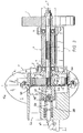
- variable resistance device 17 includes a first body 18 that is keyed to one end of axle 13 and a second body 19 that slides over a slotted extension 21 of shaft 13. Slotted extension 21 is screwed onto the tapered and threaded end of shaft 13. Bodies 18 and 19 are accommodated in a hermetically sealed chamber 20, which is partially filled with a viscous fluid. The amount of fluid that fills chamber 20 can vary, depending on the intensity of the desired braking effect. Generally, however, once the fluid is introduced to the chamber 20, its quantity is not changed.
- Body 18 is disk shaped and may be made of metallic or plastic material having a diameter of, for example, 50 to 100 mm and a thickness of approximately 15 mm, with parallel and flat faces, a circular peripheral surface, and a central hole. Body 18 is fixed to shaft 13 by any desired means, such as by slotted extension 21. Body 18 has four through holes 24 parallel to the axis a of roller 2. The holes are arranged along a circumference that is concentric to the axis a , in diametrically opposite and equidistant positions.
- Second body 19 is a made of cast zinc or aluminum (other suitable materials may be used) and comprises a central disk having an elongated collar 22 on one side and four pegs 23 on the otherside, with a central hole to receive slotted extension 21. Pegs 23 are configured to mate with holes 24 in body 18. At the end of collar 22 distal from the central disk of body 19, a bearing 25 is held in place by a rod and spring plate assembly 26 and screw 27.
- a spring 28 biases body 19 toward body 18 by pressing on the spring plate assembly 26. During rotation of body 19, the spring plate assembly is isolated from the rotation by the bearing 25.
- the distance between body 18 and body 19 may be varied by withdrawing a portion of rod 26 from chamber 20.
- the resulting gap 29 between bodies 18 and 19 permits viscous fluid to frictionally resist the rotation of the bodies over a greater surface area than that of Fig. 3.
- the resistance varies depending on the size of the gap 29, as shown in Fig. 7.
- the chamber 20 is preferably formed by two facing housing members 30 and 31.
- the first housing member 30 has a side wall 32 that is substantially flat and a peripheral wall 33 that has an approximately cylindrical shape, with a slightly larger diameter than body 18 and with a connecting flange 34.
- the second housing member 31 has a substantially cylindrical shape and has a peripheral flange 35 that can be coupled to flange 34 of first housing member 30 by means of screws 36 and sealing o-ring 37.
- a filling hole 38 communicates with the chamber 20 by means of a central hole 39, and is provided with a screw-on plug 40 for introducing the fluid to the chamber.
- the fluid may be a silicone fluid, such as those known in the art.
- Both housing members 30 and 31 have respective rows of substantially flat and parallel cooling fins 41 and 42 on their outer surfaces to conduct and radiate heat.
- fins 41 and 42 are arranged in an approximately vertical or slightly inclined direction when mounted on the stand 4, so as to facilitate heat dissipation and cooling of the viscous fluid. Furthermore, the outer edges of the cooling fins 41 and 42 may be shaped so as to form a particular oval structure, as shown in Figures 4 and 5.
- Rod 26 extends from the inside to the outside of housing member 31. Attached to the outside of housing member 31, a cam assembly 43 controls the depth of penetration of rod 26 into the chamber 20.
- cam assembly 43 is attached to a remote selectively positionable switch on the handlebar of the bicycle (not shown) by way of cable 44. The rider of the bicycle is able to use the remote switch to adjust the amount of resistance to the rotation of the bicycle wheel by varying the gap between bodies 18 and 19.
- Figure 6 plots the curves of the operation of the device according to the invention, at minimum and maximum resistance, over a range of rotational speeds. It shows the general linear variation in resistance force on the vertical axis vs speed of rotation on the horizontal axis.
- Figure 7 plots the curves of the operation of the device according to the invention, at various distances between the faces of the rotating bodies, for a constant rotational speed. It illustrates the fact that the resistance increases as the gap between the rotating bodies increases. This is believed to occur because the fluid that is near the center of the bodies rotates with the bodies creating no friction as long as the gap is below a certain distance, which is general greater than most of the gap sizes provided for in the apparatus. The amount the fluid that rotates along with the bodies decreases with gap size, and the non-rotating fluid provides additional frictional drag on the bodies. This phenomenon is illustrated in Figures 8 and 9, which show the estimated location of fluid creating frictional drag on the disk surfaces during operation of the device.
- the spring may be used to urge the bodies apart instead of together, with the cam assembly arranged to drive them together in opposition to the spring.
- the camming mechanism may be substituted by a screw mechanism.
- Various other alliterative mechanisms may be used also.
- the present invention provides for a method of varying a resistance to rotation comprising
Landscapes
- Health & Medical Sciences (AREA)
- General Health & Medical Sciences (AREA)
- Physical Education & Sports Medicine (AREA)
- Life Sciences & Earth Sciences (AREA)
- Biophysics (AREA)
- Orthopedic Medicine & Surgery (AREA)
- Fluid-Damping Devices (AREA)
- Braking Arrangements (AREA)
- Rehabilitation Tools (AREA)
- Motorcycle And Bicycle Frame (AREA)
- Axle Suspensions And Sidecars For Cycles (AREA)
- Transmission Devices (AREA)
Applications Claiming Priority (2)
| Application Number | Priority Date | Filing Date | Title |
|---|---|---|---|
| US917391 | 1997-08-25 | ||
| US08/917,391 US5916068A (en) | 1997-08-25 | 1997-08-25 | Variable resistance device |
Publications (3)
| Publication Number | Publication Date |
|---|---|
| EP0900579A2 true EP0900579A2 (de) | 1999-03-10 |
| EP0900579A3 EP0900579A3 (de) | 1999-12-22 |
| EP0900579B1 EP0900579B1 (de) | 2006-01-25 |
Family
ID=25438724
Family Applications (1)
| Application Number | Title | Priority Date | Filing Date |
|---|---|---|---|
| EP98201861A Expired - Lifetime EP0900579B1 (de) | 1997-08-25 | 1998-06-05 | Vorrichtung zum Variieren des Widerstandes für ein Fahrradtrainingsgerät |
Country Status (5)
| Country | Link |
|---|---|
| US (1) | US5916068A (de) |
| EP (1) | EP0900579B1 (de) |
| AT (1) | ATE316407T1 (de) |
| DE (1) | DE69833296T2 (de) |
| ES (1) | ES2256912T3 (de) |
Cited By (1)
| Publication number | Priority date | Publication date | Assignee | Title |
|---|---|---|---|---|
| FR2809631A1 (fr) * | 2000-06-05 | 2001-12-07 | Graber Products Inc | Dispositif de dissipation thermique pour une unite de fourniture de resistance dans un equipement d'exercice |
Families Citing this family (15)
| Publication number | Priority date | Publication date | Assignee | Title |
|---|---|---|---|---|
| WO2001052940A2 (en) * | 2000-01-21 | 2001-07-26 | Kurt Manufacturing Company, Inc. | Bicycle trainer with movable resistance device |
| US6500098B1 (en) * | 2000-04-22 | 2002-12-31 | Todd R. Werner | Bicycle training apparatus |
| GB2363082B (en) * | 2000-06-06 | 2004-06-02 | Clive Graham Stevens | Resistance adjusting device for an exercise device having a wheel driven by a belt |
| US6620081B2 (en) | 2001-07-20 | 2003-09-16 | Cal M. Phillips | Exercise stand and centrifugal resistance unit for a bicycle |
| US7628739B2 (en) * | 2001-08-09 | 2009-12-08 | Michael Gearon | Variable resistance device for an exercise machine |
| ITVI20010198A1 (it) * | 2001-09-19 | 2003-03-19 | Elite Srl | Gruppo freno in particolare per dispositivo di allenamento ciclistico |
| US20040150180A1 (en) * | 2003-01-31 | 2004-08-05 | The Little Tikes Company, A Corporation Of The State Of Ohio | Wheel tensioning mechanism |
| US20060217237A1 (en) * | 2004-12-30 | 2006-09-28 | Rhodes Jeffrey F | Exercise apparatus |
| DE102006021944A1 (de) * | 2006-05-11 | 2007-11-15 | Trw Automotive Gmbh | Rotationsdämpfer |
| FR2915170B1 (fr) * | 2007-04-20 | 2010-01-22 | Alain Laquieze | Dispositif antivol de maintien en stationnement d'un vehicule a deux roues |
| US20090152059A1 (en) * | 2007-12-12 | 2009-06-18 | Nathan Paul Womack | Rotational Resistance Apparatus |
| US9259633B2 (en) * | 2011-08-11 | 2016-02-16 | Kurt Manufacturing Company, Inc. | Roller assembly having internal resistance components |
| US9339678B2 (en) * | 2013-01-17 | 2016-05-17 | Christopher G. Gallagher | Modular resistance force system |
| US10010894B2 (en) | 2013-09-20 | 2018-07-03 | Stoneage, Inc. | Apparatus for retarding rotary nozzle speed |
| USD792529S1 (en) * | 2015-10-01 | 2017-07-18 | Cheh-Kang Liu | Bike trainer stand |
Family Cites Families (45)
| Publication number | Priority date | Publication date | Assignee | Title |
|---|---|---|---|---|
| US34479A (en) * | 1862-02-25 | Improvement in bellows for blow-pipes | ||
| US2988188A (en) * | 1958-11-26 | 1961-06-13 | Thompson Ramo Wooldridge Inc | Temperature sensitive drive |
| NL124727C (de) * | 1965-06-25 | 1968-08-15 | Mijnhardt C V Geb | |
| US3373992A (en) * | 1965-09-17 | 1968-03-19 | Gilbert K. Ludeman | Bicycle exerciser |
| US3400796A (en) * | 1966-08-10 | 1968-09-10 | Mobil Oil Corp | Power transmission device employing a shear thickening liquid |
| US3494616A (en) * | 1968-02-15 | 1970-02-10 | Billie D Parsons | Cycle-type exerciser having a fluid pump resistance |
| US3498431A (en) * | 1969-01-13 | 1970-03-03 | Eaton Yale & Towne | Fluid coupling mechanism |
| GB1279201A (en) * | 1970-03-04 | 1972-06-28 | John Dennis Brooke | Improvements in apparatus for measuring human physical work or for exercising |
| US3831942A (en) * | 1973-02-13 | 1974-08-27 | Del Mar Eng Lab | Portable exercise machine |
| US4186320A (en) * | 1977-10-21 | 1980-01-29 | Electromatic Drive Corporation | Hysteresis brake assembly |
| US4152617A (en) * | 1977-11-22 | 1979-05-01 | Dana Corporation | Selectively variable torque magnetic brake |
| US4171802A (en) * | 1977-12-12 | 1979-10-23 | Stoecker Carl H | Hydraulic torque reaction wrist and arm exerciser |
| US4441705A (en) * | 1978-08-14 | 1984-04-10 | Brown Lawrence G | Exercising apparatus |
| USD264954S (en) | 1979-08-29 | 1982-06-15 | Jim Blackburn Designs | Bicycle bottle cage |
| US4520284A (en) * | 1983-08-12 | 1985-05-28 | Eaton Corporation | Rolled housing for eddy current coupling |
| US4602373A (en) * | 1983-09-09 | 1986-07-22 | Roy S. Robinson | Variable reactive force exercise device |
| USD292900S (en) | 1984-01-05 | 1987-11-24 | Jim Blackburn Designs, Inc. | Pair of front pannier support racks for bicycles |
| USD285426S (en) | 1984-05-24 | 1986-09-02 | Jim Blackburn Designs, Inc. | Rear pannier rack for bicycles |
| JPS6179474A (ja) * | 1984-09-26 | 1986-04-23 | ツノダ自転車株式会社 | 踏込式運動器具 |
| US4640449A (en) * | 1985-01-10 | 1987-02-03 | Jim Blackburn Designs, Inc. | Handle bar mounted quick disconnect bottle cage |
| US4645199A (en) * | 1985-01-25 | 1987-02-24 | Bio-Dynamic Innovations, Inc. | Exercise device |
| US4741529A (en) * | 1985-01-25 | 1988-05-03 | Bio-Dynamic Innovations, Inc. | Exercise apparatus |
| JPS61187874A (ja) * | 1985-02-15 | 1986-08-21 | 株式会社キャットアイ | 負荷装置 |
| USD298156S (en) | 1985-11-27 | 1988-10-18 | Blackburn Designs, Inc. | Bicycle exerciser |
| JPH0679620B2 (ja) * | 1986-02-20 | 1994-10-12 | 株式会社箕浦荷台スタンド製作所 | 室内運動具における抵抗付与装置 |
| USRE34479E (en) | 1986-02-20 | 1993-12-14 | Minoura Carrier & Stand Works Co., Ltd. | Resistence applying means for exercising apparatus |
| USD299225S (en) | 1986-06-11 | 1989-01-03 | Jim Blackburn Designs, Inc. | Bicycle front rack |
| USD299818S (en) | 1986-06-11 | 1989-02-14 | Jim Blackburn Designs, Inc. | Bicycle rear rack |
| US4768782A (en) * | 1987-02-09 | 1988-09-06 | Blackburn Designs, Inc. | Bicycle exercising apparatus |
| USD306193S (en) | 1987-03-09 | 1990-02-20 | Jim Blackburn Designs, Inc. | Bicycle exercise support |
| US4822037A (en) * | 1987-06-05 | 1989-04-18 | Digital Kinetics Corporation | Resistance control system for muscle therapy/exercise/training and strength measurement |
| US5050865A (en) * | 1987-12-28 | 1991-09-24 | Quent Augspurger | Cycle training device |
| US4817939A (en) * | 1987-12-28 | 1989-04-04 | Quent Augspurger | Cycle training device |
| FR2627643B1 (fr) * | 1988-02-23 | 1990-12-21 | Labavia | Perfectionnements aux rotors induits des ralentisseurs electromagnetiques |
| US4979735A (en) * | 1988-08-01 | 1990-12-25 | Stewart John V | Hydraulic exercise device with work measurement |
| USD329035S (en) | 1989-09-29 | 1992-09-01 | Blackburn Designs, Inc. | Vehicle attached bicycle carrier |
| US5026047A (en) * | 1989-09-29 | 1991-06-25 | Kosecoff Irving W | Quick release mechanism for bicycle trainer |
| US5056700A (en) * | 1989-09-29 | 1991-10-15 | Blackburn Designs, Inc. | Automobile mountable bicycle carrier |
| DE4036230C2 (de) * | 1989-11-27 | 1995-01-05 | Viscodrive Japan | Schaltbare Viskokupplung |
| JPH0549712A (ja) * | 1991-08-27 | 1993-03-02 | Minoura Nidai Stand Seisakusho:Kk | 自転車用運動器具 |
| US5195936A (en) * | 1991-12-09 | 1993-03-23 | Gemini Mercantile Inc. | Exercise device having fluid resistance |
| US5397285A (en) * | 1993-09-08 | 1995-03-14 | Haan; Kenneth | Centrifugal resistance device for stationary bicycle trainer |
| US5542507A (en) * | 1994-11-22 | 1996-08-06 | Vibratech, Inc. | Position dependent variable output torque viscous damper |
| US5611759A (en) * | 1995-06-26 | 1997-03-18 | Cycle-Ops Products, Inc. | Resistance device for bicycle trainers |
| AU9295498A (en) * | 1997-08-29 | 1999-03-16 | Cycle-Ops Products, Inc. | Exercise resistance device |
-
1997
- 1997-08-25 US US08/917,391 patent/US5916068A/en not_active Expired - Lifetime
-
1998
- 1998-06-05 AT AT98201861T patent/ATE316407T1/de not_active IP Right Cessation
- 1998-06-05 EP EP98201861A patent/EP0900579B1/de not_active Expired - Lifetime
- 1998-06-05 DE DE69833296T patent/DE69833296T2/de not_active Expired - Fee Related
- 1998-06-05 ES ES98201861T patent/ES2256912T3/es not_active Expired - Lifetime
Cited By (1)
| Publication number | Priority date | Publication date | Assignee | Title |
|---|---|---|---|---|
| FR2809631A1 (fr) * | 2000-06-05 | 2001-12-07 | Graber Products Inc | Dispositif de dissipation thermique pour une unite de fourniture de resistance dans un equipement d'exercice |
Also Published As
| Publication number | Publication date |
|---|---|
| DE69833296D1 (de) | 2006-04-13 |
| US5916068A (en) | 1999-06-29 |
| EP0900579B1 (de) | 2006-01-25 |
| ES2256912T3 (es) | 2006-07-16 |
| EP0900579A3 (de) | 1999-12-22 |
| ATE316407T1 (de) | 2006-02-15 |
| DE69833296T2 (de) | 2006-11-16 |
Similar Documents
| Publication | Publication Date | Title |
|---|---|---|
| EP0900579B1 (de) | Vorrichtung zum Variieren des Widerstandes für ein Fahrradtrainingsgerät | |
| US6186290B1 (en) | Magnetorheological brake with integrated flywheel | |
| US6488611B1 (en) | Exercise resistance device | |
| US7011607B2 (en) | Variable magnetic resistance unit for an exercise device | |
| US6945916B2 (en) | Exercise resistance device with magnets | |
| US6964633B2 (en) | Exercise device with an adjustable magnetic resistance arrangement | |
| US5944637A (en) | Resistance device for bicycle trainers | |
| US6551220B1 (en) | Exercise resistance device with magnets | |
| US6042517A (en) | Bicycle trainer magnetic resistance device | |
| US4441705A (en) | Exercising apparatus | |
| US5397285A (en) | Centrifugal resistance device for stationary bicycle trainer | |
| US4645199A (en) | Exercise device | |
| US5051638A (en) | Magnetically variable air resistance wheel for exercise devices | |
| US9259633B2 (en) | Roller assembly having internal resistance components | |
| FI94315B (fi) | Polkupyöräilyn valmennuslaite | |
| US6234939B1 (en) | Unipedal cycle apparatus | |
| US5542507A (en) | Position dependent variable output torque viscous damper | |
| US5611759A (en) | Resistance device for bicycle trainers | |
| US20180264305A1 (en) | Eddy current cycling resistance apparatus | |
| US5792030A (en) | Braked roller device for cycling training | |
| US20040130228A1 (en) | Magnetic induction coupler | |
| CN217139084U (zh) | 一种可调节液阻装置及自行车训练器 | |
| CN210159152U (zh) | 一种健身车飞轮结构 | |
| US4655730A (en) | Automatic gear box | |
| EP1524756A1 (de) | Magnetische Induktionskupplung |
Legal Events
| Date | Code | Title | Description |
|---|---|---|---|
| PUAI | Public reference made under article 153(3) epc to a published international application that has entered the european phase |
Free format text: ORIGINAL CODE: 0009012 |
|
| AK | Designated contracting states |
Kind code of ref document: A2 Designated state(s): AT BE CH DE ES FI FR GB IT LI NL PT SE |
|
| AX | Request for extension of the european patent |
Free format text: AL;LT;LV;MK;RO;SI |
|
| PUAL | Search report despatched |
Free format text: ORIGINAL CODE: 0009013 |
|
| AK | Designated contracting states |
Kind code of ref document: A3 Designated state(s): AT BE CH CY DE DK ES FI FR GB GR IE IT LI LU MC NL PT SE |
|
| AX | Request for extension of the european patent |
Free format text: AL;LT;LV;MK;RO;SI |
|
| 17P | Request for examination filed |
Effective date: 20000606 |
|
| AKX | Designation fees paid |
Free format text: AT BE CH DE ES FI FR GB IT LI NL PT SE |
|
| GRAP | Despatch of communication of intention to grant a patent |
Free format text: ORIGINAL CODE: EPIDOSNIGR1 |
|
| GRAS | Grant fee paid |
Free format text: ORIGINAL CODE: EPIDOSNIGR3 |
|
| GRAA | (expected) grant |
Free format text: ORIGINAL CODE: 0009210 |
|
| AK | Designated contracting states |
Kind code of ref document: B1 Designated state(s): AT BE CH DE ES FI FR GB IT LI NL PT SE |
|
| PG25 | Lapsed in a contracting state [announced via postgrant information from national office to epo] |
Ref country code: LI Free format text: LAPSE BECAUSE OF FAILURE TO SUBMIT A TRANSLATION OF THE DESCRIPTION OR TO PAY THE FEE WITHIN THE PRESCRIBED TIME-LIMIT Effective date: 20060125 Ref country code: FI Free format text: LAPSE BECAUSE OF FAILURE TO SUBMIT A TRANSLATION OF THE DESCRIPTION OR TO PAY THE FEE WITHIN THE PRESCRIBED TIME-LIMIT Effective date: 20060125 Ref country code: CH Free format text: LAPSE BECAUSE OF FAILURE TO SUBMIT A TRANSLATION OF THE DESCRIPTION OR TO PAY THE FEE WITHIN THE PRESCRIBED TIME-LIMIT Effective date: 20060125 Ref country code: BE Free format text: LAPSE BECAUSE OF FAILURE TO SUBMIT A TRANSLATION OF THE DESCRIPTION OR TO PAY THE FEE WITHIN THE PRESCRIBED TIME-LIMIT Effective date: 20060125 Ref country code: AT Free format text: LAPSE BECAUSE OF FAILURE TO SUBMIT A TRANSLATION OF THE DESCRIPTION OR TO PAY THE FEE WITHIN THE PRESCRIBED TIME-LIMIT Effective date: 20060125 |
|
| REG | Reference to a national code |
Ref country code: GB Ref legal event code: FG4D |
|
| REG | Reference to a national code |
Ref country code: CH Ref legal event code: EP |
|
| REF | Corresponds to: |
Ref document number: 69833296 Country of ref document: DE Date of ref document: 20060413 Kind code of ref document: P |
|
| PG25 | Lapsed in a contracting state [announced via postgrant information from national office to epo] |
Ref country code: SE Free format text: LAPSE BECAUSE OF FAILURE TO SUBMIT A TRANSLATION OF THE DESCRIPTION OR TO PAY THE FEE WITHIN THE PRESCRIBED TIME-LIMIT Effective date: 20060425 |
|
| PGFP | Annual fee paid to national office [announced via postgrant information from national office to epo] |
Ref country code: GB Payment date: 20060523 Year of fee payment: 9 |
|
| PGFP | Annual fee paid to national office [announced via postgrant information from national office to epo] |
Ref country code: ES Payment date: 20060605 Year of fee payment: 9 |
|
| PGFP | Annual fee paid to national office [announced via postgrant information from national office to epo] |
Ref country code: NL Payment date: 20060614 Year of fee payment: 9 |
|
| PG25 | Lapsed in a contracting state [announced via postgrant information from national office to epo] |
Ref country code: PT Free format text: LAPSE BECAUSE OF FAILURE TO SUBMIT A TRANSLATION OF THE DESCRIPTION OR TO PAY THE FEE WITHIN THE PRESCRIBED TIME-LIMIT Effective date: 20060626 |
|
| PGFP | Annual fee paid to national office [announced via postgrant information from national office to epo] |
Ref country code: FR Payment date: 20060629 Year of fee payment: 9 |
|
| PGFP | Annual fee paid to national office [announced via postgrant information from national office to epo] |
Ref country code: IT Payment date: 20060630 Year of fee payment: 9 |
|
| REG | Reference to a national code |
Ref country code: ES Ref legal event code: FG2A Ref document number: 2256912 Country of ref document: ES Kind code of ref document: T3 |
|
| REG | Reference to a national code |
Ref country code: CH Ref legal event code: PL |
|
| PGFP | Annual fee paid to national office [announced via postgrant information from national office to epo] |
Ref country code: DE Payment date: 20060821 Year of fee payment: 9 |
|
| ET | Fr: translation filed | ||
| PLBE | No opposition filed within time limit |
Free format text: ORIGINAL CODE: 0009261 |
|
| STAA | Information on the status of an ep patent application or granted ep patent |
Free format text: STATUS: NO OPPOSITION FILED WITHIN TIME LIMIT |
|
| 26N | No opposition filed |
Effective date: 20061026 |
|
| GBPC | Gb: european patent ceased through non-payment of renewal fee |
Effective date: 20070605 |
|
| NLV4 | Nl: lapsed or anulled due to non-payment of the annual fee |
Effective date: 20080101 |
|
| REG | Reference to a national code |
Ref country code: FR Ref legal event code: ST Effective date: 20080229 |
|
| PG25 | Lapsed in a contracting state [announced via postgrant information from national office to epo] |
Ref country code: NL Free format text: LAPSE BECAUSE OF NON-PAYMENT OF DUE FEES Effective date: 20080101 Ref country code: DE Free format text: LAPSE BECAUSE OF NON-PAYMENT OF DUE FEES Effective date: 20080101 |
|
| PG25 | Lapsed in a contracting state [announced via postgrant information from national office to epo] |
Ref country code: GB Free format text: LAPSE BECAUSE OF NON-PAYMENT OF DUE FEES Effective date: 20070605 |
|
| REG | Reference to a national code |
Ref country code: ES Ref legal event code: FD2A Effective date: 20070606 |
|
| PG25 | Lapsed in a contracting state [announced via postgrant information from national office to epo] |
Ref country code: FR Free format text: LAPSE BECAUSE OF NON-PAYMENT OF DUE FEES Effective date: 20070702 |
|
| PG25 | Lapsed in a contracting state [announced via postgrant information from national office to epo] |
Ref country code: ES Free format text: LAPSE BECAUSE OF NON-PAYMENT OF DUE FEES Effective date: 20070606 |
|
| PG25 | Lapsed in a contracting state [announced via postgrant information from national office to epo] |
Ref country code: IT Free format text: LAPSE BECAUSE OF NON-PAYMENT OF DUE FEES Effective date: 20070605 |