EP0900146B1 - Kompressible blattabgabevorrichtung - Google Patents
Kompressible blattabgabevorrichtung Download PDFInfo
- Publication number
- EP0900146B1 EP0900146B1 EP97909028A EP97909028A EP0900146B1 EP 0900146 B1 EP0900146 B1 EP 0900146B1 EP 97909028 A EP97909028 A EP 97909028A EP 97909028 A EP97909028 A EP 97909028A EP 0900146 B1 EP0900146 B1 EP 0900146B1
- Authority
- EP
- European Patent Office
- Prior art keywords
- front wall
- stack
- sheet
- projecting
- sheets
- Prior art date
- Legal status (The legal status is an assumption and is not a legal conclusion. Google has not performed a legal analysis and makes no representation as to the accuracy of the status listed.)
- Expired - Lifetime
Links
Images


Classifications
-
- B—PERFORMING OPERATIONS; TRANSPORTING
- B42—BOOKBINDING; ALBUMS; FILES; SPECIAL PRINTED MATTER
- B42D—BOOKS; BOOK COVERS; LOOSE LEAVES; PRINTED MATTER CHARACTERISED BY IDENTIFICATION OR SECURITY FEATURES; PRINTED MATTER OF SPECIAL FORMAT OR STYLE NOT OTHERWISE PROVIDED FOR; DEVICES FOR USE THEREWITH AND NOT OTHERWISE PROVIDED FOR; MOVABLE-STRIP WRITING OR READING APPARATUS
- B42D5/00—Sheets united without binding to form pads or blocks
- B42D5/003—Note-pads
- B42D5/005—Supports for note-pads
Definitions
- the invention relates to dispensers for sheets from a coherent stack of sheets, each sheet bearing at least a band of pressure-sensitive adhesive, such as a repositionable pressure-sensitive adhesive, by which it can be self-adhered to a variety of surfaces.
- the invention is particularly related to such dispensers which have low profiles so that they can be attached to an inside page of a magazine, catalog, notebook, personal organizer or the like without creating an unsightly bulge.
- US-A-5,158,205 discloses a rather low profile dispenser for a stack of paper sheets.
- a dispenser made of folded card stock forms a chamber closely containing a stack (12) of paper sheets.
- Centrally across the top wall (22) of that dispenser is a slot (30) through which paper sheets can be successively pulled from the stack.
- Each of the sheets has a narrow band of repositionable pressure-sensitive adhesive (14) coated on one surface adjacent one edge.
- flanking slits (24) at each end of the slot allow one of two opposed flap-like portions (28) of the top wall to flex as shown in Figure 4 while the other flap-like portion places a drag on the next sheet so that the uppermost sheet will peel away from the next sheet.
- U.S.-A-5,411,168 and US-A-5,397,117 describe low profile sheet dispenser subassemblies and low profile sheet dispensers for coherent stacks of "Post-it” (R) brand self-slick repositionable notes, for coherent stacks of "Post-it” (R) brand repositionable lape flags described in U.S.-A-4,907,825, and other coherent stacks of adhesive-bearing sheets such as those described in U.S.-A-4,895,746 and U.S.-A-5,086,946.
- These known low profile sheet dispenser subassemblies or sheet dispensers are adapted to be adhered to a substrate such as on an inside page of a book, catalog, brochure, personal organizer or the like.
- a sheet dispenser is known as defined in the preamble of claim 1.
- This known dispenser is provided with a housing defining a chamber for receiving the stack of sheets.
- the housing comprises a front wall with front wall portions having confronting each other and defining a slot therebetween. These parts of the front wall portions have to be manually erected so as to be moved from a retracted position in which they are generally parallel with the sheets of the stack, to a projecting position in which they project from above the stack of sheets.
- the present invention provides an improved novel structure for sheet dispensers including coherent stacks of "Post-it” (R) brand self-stick repositionable notes, "Post-it” (R) brand tape flags, or lengths of adhesive coated tape in a housing; which dispensers have low profiles like the above-discussed low-profile dispensers, permitting them to be positioned unobtrusively on an inside page of a closed book, catalog, brochure, personal organizer or the like, while still, when exposed for use, presenting an end of the next sheet to be dispensed in a position projecting above an outer surface of the housing for the dispenser where it can be easily grasped by a person wishing to withdraw the sheet from the dispenser.
- the sheet dispenser comprises a stack of dispensable sheets (e.g., repositionable paper notes, tape flags, or lengths of adhesive coated tape) disposed one on top of another; and a housing having walls defining a chamber in which the stack of dispensable sheets is positioned.
- the walls defining the chamber include a rear wall positioned adjacent the lowermost sheet in the stack and a front wall having an outer surface opposite the chamber and having adjacent edges defining a through slot extending transversely across the stack.
- the first end portion of the uppermost dispensable sheet in the stack projects through the slot
- the dispensable sheets include means for releasably adhering the uppermost sheet to the first end portion of the underlying sheet in the stack sufficiently to carry the first end of the underlying sheet through the slot when the first sheet is removed from the dispenser by manually pulling the first end portion of the uppermost sheet through the slot and to thereby position the first end portion of the underlying dispensable sheet in a position extending through the slot as a result of the dispensing.
- the front wall of the housing is repeatably movable between (a) a projecting position with the front wall projecting above the stack and disposed to support the first end portion of the uppermost sheet in a position projecting above the outer surface of the front wall; and (b) a retracted position with the front wall disposed closer to and generally parallel with the sheets on the stack to reduce the thickness of the dispenser with the front wall portions being resiliently flexible and compressible to the retracted position. Movement to the retracted position can be caused, for example, by closing a book with the dispenser positioned between the pages of that book.
- Dispensers according to the present invention can be either (1) of the type in which the bottom sheet of the stack of sheets is attached to the rear wall of the housing or the stack is otherwise restricted from significant movement in the chamber and the sheets are dispensed through a fairly wide slot as is taught in U.S.-A-5,518,144, or (2) of the type in which the stack of sheets is free to reciprocate in the housing as the sheets are dispensed and the sheets are dispensed through a rather narrow slot as is taught in U.S.-A-4,907,825 (Miles et al).
- the front wall comprises front wall portions formed of resiliently flexible material. Those front wall portions provide the adjacent edges that define the slot and have proximal ends attached to the rear wall. In the projecting position parts of the front wall portions project above the stack to support the first end portion of the uppermost sheet in a position projecting above the outer surface of the front wall; and the front wall portions are resiliently bendable to the retracted position with the first end portion of the uppermost sheet and the front wall portions disposed generally parallel with the other sheets on the stack to reduce the thickness of the dispenser.
- each front wall portion has two sections that are generally planar, are attached side to side to each other at adjacent sides, and, in the projecting position of the front wall portions, are disposed at an included angle in the range of about 60 to 140 degrees with respect to each other with the adjacent sides of the sections providing the parts of the front wall portions that will support the first end portion of the uppermost sheet in a position projecting above the outer surface of the front wall.
- the front wall is formed of resiliently flexible material (e.g., tag board or polymeric material), and is attached to a rear wall of the housing along its periphery with the front wall normally arched away from the rear wall.
- the dispenser includes means for retaining the stack along the rear wall of the housing so that the arched front wall above the stack supports the first end portion of the uppermost sheet in a position projecting above the outer surface of the front wall.
- the front wall is then resiliently compressible to the retracted position with the front wall and the first end portion of the uppermost sheet on the stack disposed generally parallel with the other sheets in the stack to reduce the thickness of the dispenser.
- the front wall comprises an outer layer of limp flexible material defining its outer surface, and a layer of resiliently compressible material between its outer layer and the stack of dispensable sheets which normally positions the front wall in its projecting position with its edges defining the slot in a position projecting above the stack to support the first end portion of the uppermost sheet in a position projecting above the outer surface of the front wall.
- That layer of resiliently compressible material is resiliently compressible to the retracted position of the front wall at which its outer surface is disposed closer to the sheets on the stack to reduce the thickness of the dispenser.
- the front wall comprises a front wall portion formed of stiff material having a through passageway aligned with and generally corresponding in size and shape to the slot, and two resiliently flexible front wall portions of resiliently flexible material.
- the flexible front wall portions have attached end parts attached along the inner surface of the front wall portion on opposite sides of the passageway and projecting end parts adapted to project across the passageway in overlapped relationship. The first end portion of the uppermost sheet projects between the end parts and through the slot.
- the projecting end parts can be manually returned to their overlapped relationship with the first end portion of the new uppermost sheet in the stack projecting between tile end parts and laying along the outer surface of the front wall, as may be desired to store the dispenser between the pages of a book or organizer.
- the sheet dispenser 10 includes a housing 12, and a stack 14 of dispensable sheets 18 (later to be generally explained, but which could be a stack of the "Post-it” (R) brand tape flags sold by Minnesota Mining and Manufacturing Company, St. Paul, MN) in a chamber 13 defined by walls of the housing 12.
- the dispenser 10 is of the type in which the bottom sheet of the stack 14 of sheets 18 is attached to the rear wall of the housing 12 and the sheets 18 are dispensed through a fairly wide slot as is taught in U.S.-A-5,518,144.
- Portions 16 of a front wall of the housing 12 have edges 17 that define that slot through which a first end portion 20 of the top sheet 18 on the stack 14 projects. As shown in Figure 1, parts 25 of those front wall portions 16 normally project above the top surface of the stack 14 of sheets to position that first end portion 20 of the top sheet 18 in a position projecting above an outer surface of the front wall where the end portion 20 can be easily grasped to withdraw the top sheet 18 from the housing 12.
- the front wall portions 16 are of flexible material so that, as is shown in Figure 2, they can be resiliently bent to lie along the top surface of the stack 14 of sheets and thereby reduce the thickness of the dispenser 10 when, for example, the dispenser 10 is positioned on one of the pages of a book, magazine, personal organizer or the like that is closed so that a surface such as a surface represented by the dotted line 15 presses the front wall portions 16 against the stack 14.
- the stack 14 in the dispenser 10 is of dispensable sheets 18 disposed one on top of another and including an uppermost sheet and a lowermost sheet.
- Each sheet 18 in the stack 14 comprises a backing 19 that has opposite upper and lower major side surfaces and opposite first and second ends with ends of the sheets being in alignment in the stack 14, and has a layer 21 of adhesive permanently adhered to the lower side surface of the backing 19.
- the layers 21 of adhesive of the sheets 18 are releasably adhered along the upper surfaces of the adjacent sheets in the stack 14.
- the sheets 18 comprise release means for providing a first adhesion level along first end portions 22 of the sheets adjacent the first ends of the backings between the lower side surfaces and the upper side surfaces of the adjacent sheets 18 in the stack 14 to which the layers 21 of adhesive are releasably adhered, which first adhesion level requires a sufficiently low or no release force between the lower side surfaces and the adjacent sheets 18 to which the layers 21 of adhesive along those lower side surfaces are releasable adhered to afford sliding and/or lifting movement between the side surfaces of the adjacent sheets 18 along the first end portions 22.
- Attachment means provide a second adhesion level along second end portions 23 of the sheets 18 adjacent the second ends of the backings 19 between the layers 20 of adhesive and the upper side surfaces of the adjacent sheets 18 in the stack 14 to which the layers 20 of adhesive are releasably adhered, which second adhesion level provides a release force that is higher than the sufficiently low or no release force along the first end portions 22 and firmly adhere the sheets 18 to the adjacent sheets 18 in the stack 14 during sliding and/or lifting movement of the sheets 18 relative to the adjacent sheets 18 along the first end portions 22 while affording peeling away of the sheets from the stack 14 along the second end portions 22.
- the sheets 18 illustrated have no coating of adhesive along their first end portions 22 so that the first adhesive level requires no release force to afford sliding and/or lifting movement between the side surfaces of the adjacent sheets 18 along the first end portions 22.
- the sheets could be coated with adhesive along their entire lengths in which case a layer of release material would be required on the upper surface of the sheet 18 to which the adhesive on the first end portion 22 is adhered to provide the sufficiently low adhesive level that affords sliding and/or lifting movement between the side surfaces of the adjacent sheets 18 along the first end portions 22 and a second release level along the second end portion 23.
- the walls defining the chamber in 13 in the housing 12 include a rear wall 26 positioned adjacent the lowermost sheet 18 in the stack 14 to which that lowermost sheet 18 is adhered, and the front wall that has the adjacent edges 17 defining the through slot extending transversely across the stack 14 through which the first end portion 20 of the uppermost dispensable sheet 18 in the stack 14 projects.
- the stack 14 of dispensable sheets 18 and the housing 12 are adapted to afford dispensing of the dispensable sheet 18 having its first end portion 20 extending through the slot when that first end portion 20 is manually pulled through the slot by sequential sliding and/or lifting movement of one of the dispensable sheets 18 relative to the adjacent dispensable sheet 18 along the first end portion 22 and peeling away of the dispensable sheet 18 from the stack 14 along its second end portion 23, and positioning of the first end portion 20 of an underlying dispensable sheet 18 in a position extending through the slot as a result of such dispensing.
- the walls of the housing 12 for the dispenser 10 are thermoformed from one piece of a resiliently flexible polymeric material (e.g., about 0.012 inch or 0.030 centimeter thick polyester).
- the front wall of the dispenser 10 comprises the two allochiral front wall portions 16 that have at their distal ends the adjacent edges 17 that define the slot and have proximal ends 24 attached to the rear wall 26.
- Each of the front wall portions 16 includes two sections that are generally planar, are attached side to side to each other at adjacent sides, and are disposed at an included angle (e.g., about 130 degrees) with respect to each other.
- the adjacent sides of the sections provide the parts 25 of the front wall portions 16 projecting above the stack 14 to support the first end portion of the uppermost sheet in a position projecting above the outer surface of the front wall that are positioned generally centrally between the distal and proximal ends of the front wall portions 16.
- the front wall portions 16 When the front wall portions 16 are pressed toward the top of the slack 14 (e.g., by closing a book in which the dispenser is positioned) the front wall portions 16 will resiliently bend to move the parts 25 of the front wall and the first end portion 20 of the uppermost sheet 18 closer to and into alignment along the top surface of the stack 14 as is illustrated in Figure 2.
- the front wall portions 16 When that pressing force is released, however, (e.g., by again opening the book) the front wall portions 16 will again return to their normal projecting positions ( Figures 1 and 3) at which the parts 25 of the front wall portions 16 will again support the first end portion 20 of the uppermost sheet 18 in a position projecting above the outer surface of the front wall. If the sheets 18 dispensed from the dispenser 10 are coated with adhesive along their entire lengths, it is desirable to reduce the potential adhesion between that adhesive and the front wall portions 16 by embossing them or coating them with a release material.
- FIGS. 4 through 8 there are illustrated several alternate embodiments of sheet dispensers 30, 40, 50, 60, and 70 according to the present invention that are adapted to dispense sheets from the same type of stack 14 used in the dispenser 10 and like the dispenser 10 are also of the type in which the lowest sheet in the stack of sheets 14 is attached to a rear wall of the housing and the sheets 18 are dispensed through a fairly wide slot as is taught in U.S.-A-5,518,144.
- the walls of the housings for the dispensers 30 through 70 are thermoformed from one piece of a resiliently flexible polymeric material (e.g., about 0.030 centimeter or 0.012 inch thick polyester).
- the front walls for the housings each comprise two allochiral front wall portions having distal ends that provide adjacent edges defining a slot through which an end portion of the top sheet on the stack projects, and that have proximal ends opposite their distal ends that are attached to the rear wall.
- the front wall portions of the housings for the dispensers 30 through 70 have parts that normally project in a projecting position above the stack to support the first end portion of the uppermost sheet in a position projecting above the outer surface of its front wall, but which, when pressure is applied to them (e.g., by being pressed between the pages of a book) will resiliently flatten to a retracted position with the front wall portions and the first end portion of the uppermost sheet disposed closer to and generally parallel with the sheets on the stack to reduce the thickness of the dispenser.
- the dispensers 30 through 70 primarily differ from the dispenser 10 by the shape of their front wall portions.
- the dispenser 30 illustrated in Figure 4 is generally the same as the dispenser 10 illustrated in Figures 1 through 3 except that the front wall portions 32 of the housing 31, instead of being generally V-shaped in cross section, are each arcuate in cross section and have cylindrically convex surfaces opposite the rear wall 34 to provide parts 35 generally centered between the distal and proximal ends 37 and 38 of the front wall portions 32 for supporting the first end portion 20 of the uppermost sheet 18 on the stack 18 in a position projecting above the outer surface of the front wall.
- each front wall portion 43 is formed by only one planar section 44 attached to and projecting from the rear wall 45.
- planar sections 54 that define the distal ends 52 are supported at the ends of joined planar sections 57 and 58 disposed in generally inverted V-shaped orientations that bridge around the opposite ends of the stack 14 so that each of the front wall portions 53 has two sections 54 and 58 that are generally planar, are attached side to side to each other at adjacent sides, and are disposed at an included angle in the range of about 80 to 100 degrees with respect to each other.
- planar sections 64 that define the distal ends 62 are supported at the ends of joined planar sections 67 and 68 disposed generally at a right angle to each other that bridge around the opposite ends of the stack 14 so that each of the front wall portions 63 has two sections 64 and 68 that are generally planar, are attached side to side to each other at adjacent sides, and are disposed at an included angle in the range of about 120 to 140 degrees with respect to each other.
- the front wall portions 71 each comprise first and second generally planar sections 72 and 73, which first and second sections 72 and 73 are joined to each other at adjacent sides 74 and are disposed at an acute angle with respect to each other with the sides 75 of the second sections 73 opposite those adjacent sides 74 being the distal ends and being supported on the stack 14, and the adjacent sides 74 on the two front wall portions 71 being spaced apart, having the edges defining the slot, and providing parts of the front wall portions 71 for supporting the first end portions 20 of the uppermost sheet 18 in a position projecting above the outer surface of the front wall.
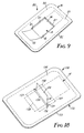
- FIG 9 illustrates a dispenser 80 according to the present invention that is of the type in which the bottom sheet of the stack 14 of sheets 18 is attached to a rear wall 82 of a housing 81 and the sheets 18 are dispensed through a fairly wide slot as is taught in U.S.-A-5,518,144.
- the dispenser 80 comprises the housing 81 including the generally rectangular rear wall 82 which is of a flexible label stock material and has a layer of pressure sensitive adhesive covered by a release liner along its outer surface.
- the housing 81 also includes a generally rectangular front wall 83 comprising an outer layer 84 of limp flexible material (e.g., a polymeric material such as 0.0035 inch or 0.0089 centimeter thick polypropylene) attached around its periphery to the periphery of the rear wall 82 and a layer 85 of resiliently compressible material (e.g., 1/8 to 3/8 inch or 3.173 to 9.525 mm thick low density polymeric foam) adhered to the inner surface of the outer layer 84.
- a layer 84 of limp flexible material e.g., a polymeric material such as 0.0035 inch or 0.0089 centimeter thick polypropylene
- a layer 85 of resiliently compressible material e.g., 1/8 to 3/8 inch or 3.173 to 9.525 mm thick low density polymeric foam
- the stack 14 of dispensable sheets is positioned in a chamber 86 defined between the compressible layer 85 and the rear wall 82 with an end portion 20 of the uppermost sheet 18 on the stack 14 projecting through an opening or slot in the front wall 83 defined by opposite edges 87.
- the compressible layer 85 normally elevates the edges 87 above the stack 14 so that the end portion 20 of the top sheet on the stack projects above the outer surface of the front wall 83.
- the layer 85 of resiliently compressible material can be resiliently compressed to a retracted position with the outer surface of the front wall 83 disposed closer to the sheets 18 on the stack 14 to reduce the thickness of the dispenser 80 when, for example, the rear wall 82 of the dispenser 80 is attached along a page in a book and the book is closed.
- the compressible layer 85 will again expand to space the edges 87 from the stack 14 and again cause the end portion 20 of the top sheet 18 to project above the outer surface of the front wall where it can be easily grasped by a person wishing to withdraw it from the dispenser 80
- the dispenser 80 could also be modified to be of the type in which the stack of sheets 14 is free to reciprocate in the chamber 86 as the sheets 18 are dispensed and the sheets 18 are dispensed through a rather narrow slot as is taught in U.S.-A-4,907,825 by making the chamber 86 sufficiently long to afford such reciprocation and moving the edges 87 closer together to narrow the slot through which the sheets are dispensed.
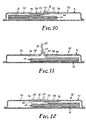
- FIGS 10 through 12 illustrate a dispenser 90 according to the present invention that is a modification of the dispenser sold under the trade designation "Post-it” (R) brand Tape Flags by Minnesota Mining and Manufacturing Co, St. Paul, MN, that is described in U.S.-A-4,770,320.
- the dispenser 90 is of the type in which the stack 14 of sheets 18 is free to reciprocate in a housing as the sheets 18 are dispensed and the sheets 18 are dispensed through a rather narrow slot as is taught in U.S.-A-4,770,320.
- the housing 91 for the dispenser 90 differs from the housing or enclosure for the dispenser described in U.S.-A-4,770,320 in that rigid projections on a front wall for the housing that defined the outlet slot for the tape flags or sheets on the dispenser described in U.S.-A-4,770,320 have been removed and replaced with two flexible front wall portions 94.
- the front wall of the housing 91 in the dispenser 90 comprises a front wall portion 92 formed of stiff polymeric material having a through passageway 93 aligned with and generally corresponding in size and shape to the slot on the dispenser described in U.S.-A-4,770,320, and the two flexible front wall portions 94 (e.g., formed of 0.002 to 0.005 inch or 0.005 to 0.0127 centimeter thick polyester which for some applications may be coated with a release agent).
- the flexible front wall portions 94 have attached end parts 96 attached along the inner surface of the front wall portion 92 on opposite sides of the passageway 93 and projecting end parts 97 adapted to project across the passageway 93 in overlapped relationship in a retracted position of the front wall 92 (see Figure 10). In that retracted position of the front wall 92 the first end portion 20 of the uppermost sheet 18 on the stack 14 projects between the projecting end parts 97, through the passageway 93, and along the outer surface of the front wall partion 92.
- the projecting end parts 97 can be manually returned to their overlapped relationship with the first end portion 20 of the new uppermost sheet 18 in the stack projecting between the overlapped end parts 97 and laying along the outer surface of the front wall 92 (see Figure 12), as may be desired to store the dispenser 90 between the pages of a book or organizer.
- Such returning of the projecting end parts 97 to their overlapped relationship can be caused by pressing the outer ends of the projecting end parts 97 and the first end portion 20 of the sheet 18 projecting between them toward the stack 14 in the dispenser 90.
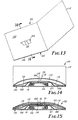
- FIGS 13, 14, 15 and 16 illustrate a ninth embodiment of a sheet dispenser according to the present invention, generally designated by the reference numeral 100, that is of the type in which the stack 14 of sheets 18 is free to reciprocate in a housing 102 as the sheets 18 are dispensed and the sheets 18 are dispensed through a rather narrow slot as is taught in U.S.-A-4,770,320.
- the sheet dispenser 100 includes the housing 102, and two stacks 14 of dispensable sheets (the stacks 14 are of one of the types described above, and as illustrated are stacks 14 of the 3/8 inch or 9.525 mm wide "Post-it" (R) brand tape flags sold by Minnesota Mining and Manufacturing Company, St.
- R Post-it
- a front wall 103 of the housing 102 has opposite edges that define a slot 104 through which end portions 20 of the top sheets 18 on the stacks 14 project.
- the front wall 103 normally projects above the top surface of the stack 14 of sheets 18 (see Figures 13 and 14) to position those end portions 20 of the top sheets 18 in a position projecting above an outer surface of the front wall 103 where they can be easily grasped to withdraw either of the top sheets 18 from the housing 102.
- the front wall 103 is of flexible material (e.g., flexible 12 to 20 point card stock) so that it can be resiliently bent to lie closer to the top surfaces of the stacks 14 ( Figure 15) and thereby reduce the thickness of the dispenser 100 when, for example the dispenser 100 is positioned on one of the pages of a book, magazine, personal organizer or the like that is closed.
- flexible material e.g., flexible 12 to 20 point card stock
- the housing 102 of the dispenser 100 includes a rectangular rear wall 106 of the same flexible material as the front wall 103, and means for retaining the stack 14 along the inner surface of its rear wall 106. That means, as illustrated, is a flexible cover layer 107 of the type described in U.S.-A-5,397,117 extending over the stacks 14 and having its periphery 108 adhered to the rear wall 106.
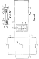
- Figure 16 illustrates a sub-assembly including the stacks 14, the cover layer 107 and a formed sheet 109 of the resiliently flexible material from which much of the housing 102 is formed
- the front wall 103 of the dispenser 100 is only a portion of that formed sheet 109 which also includes the rear wall 106, two spring portions 110 on opposite sides of the front wall 103, an attachment tab 111 at the side of the front wall 103 opposite the rear wall 106, and a cover 112 at the side of the rear wall 106 opposite the front wall 103.
- That formed sheet 109 is folded on opposite sides of the front wall 103 to position the spring portions 110 along the inner surface of the front wall 103, is then folded between the front wall 103 and the attachment tab 111 to position the attachment tab 111 along the surfaces of the spring portions 110 opposite the front wall 103, and is folded between the front wall 103 and the rear wall 106 to position the attachment tab 111 along the inner surface of the rear wall 106 to which it is adhesively attached.
- the end portions 20 of the sheets 18 are positioned to extend through opposed notches 114 in the spring portions 110 and the slot 104 in the front wall 103.
- the spring portions 110 then bridge across and lay along the cover layer 107, whereas the front wall 103 normally arches away from the spring portions 110 and cover layer 107 because of the resilience in the folds between the front wall 103 and the spring portions 110.
- the opposite edges that define the slot 104 through which the end portions 20 of the top sheets 18 on the stack 14 project support those first end portion 20 in a position projecting above the outer surface of the front wall 103 as can best be seen in Figure 14.
- the front wall 103 is resiliently moveable to a retracted position ( Figure 15) with the front wall 103 against the spring portions 110 and the first end portions 20 of the uppermost sheets 18 disposed along the outer surface of the front wall 103 to reduce the thickness of the dispenser 100.
- the cover 112 can be moved by bending the sheet 109 between the cover 112 and rear wall 106 between an open position ( Figures 13 and 14) to afford access to the projecting end portion 20 of the top sheet 18, and a closed position ( Figure 15) for both applying pressure to move the front wall 103 to its retracted position and protecting the end portions 20 of the sheets 18 when the front wall 103 is in its retracted position.
- FIG. 17 there is illustrated a tenth embodiment of a sheet dispensers 120 according to the present invention that is adapted to dispense sheets from the same type of stack 14 used in the dispenser 10 and that is of the type in which the bottom sheet of the stack 14 of sheets 18 is attached to a rear wall 123 of a housing 122 and the sheets 18 are dispensed through a fairly wide slot as is taught in U.S.-A-5,518,144.
- the dispenser 120 includes the housing 122 that has the rear wall 123, two opposite side walls 124 and opposed parallel planar sections 125 of two opposed front wall portions that are thermo formed from one piece of a stiff resiliently flexible polymeric material.
- the front wall portions of the housing 122 also include two planar sections 126 of resiliently flexible material attached at the distal ends of the stiff sections 125 by having extending portions laminated thereto.
- the flexible planar sections 126 are disposed at an included angle in the range of 100 to 160 degrees (e.g., 115 degrees) with respect to the stiff sections 125.
- the flexible sections 126 have distal ends that provide adjacent edges 127 defining a slot through which an end portion 20 of the top sheet 18 on the stack 14 projects.
- the flexible sections 126 have parts that normally project in a projecting position above the stack 14 to support the first end portion 20 of the uppermost sheet 18 in a position projecting above the outer surface of the front wall of the housing 122.
- Figure 18 illustrates a dispenser 130 according to the present invention that is of the type in which a stack 14 of sheets 18, that can be the same as the stack 14 described above, is free to reciprocate in a chamber in a housing 132 as the sheets 18 are dispensed and the sheets 18 are dispensed through a rather narrow slot as is taught in U.S.-A-4,770,320.
- the housing 132 includes a generally rectangular rear wall 133 which is of a flexible label stock material and has a layer of pressure sensitive adhesive covered by a release liner along its outer surface.
- the housing 132 also includes a generally rectangular flexible front wall including a main front wall portion 134 of a strong flexible material (e.g., a polymeric material such as 0.003 inch or 0.008 centimeter thick polypropylene) that is attached around its periphery to the periphery of the rear wall 133 and has a through centrally located passageway 136 transverse of the stack 14 of sheets 18 in the chamber.
- the front wall also includes two flexible sheet supporting front wall portions 137 (e.g., formed of 0.002 to 0.005 inch or 0.005 to 0.0127 centimeter thick polyester which for some applications may be coated with a release agent).
- the two flexible supporting front wall portions 137 have attached end parts 138 attached along the inner surface of the main front wall portion 134 on opposite sides of the passageway 136 and projecting end parts 139 projecting in opposed relationship through the passageway 136 generally at a right angle to and away from the outer surface of the main portion 134 of the front wall in a projecting position of the front wall to define an exit slot for the sheets 18 therebetween.
- the first end portion 20 of the uppermost sheet 18 in the stack then projects between the projecting end parts 139 and is supported in a position projecting above the outer surface of the main portion 134 of the front wall.
- the projecting end parts 139 will then normally support in that same position the end portions 20 of subsequent sheets 18 positioned to be withdrawn from the dispenser 130 as a result of sheets 18 being withdrawn from the dispenser 130.
- the projecting end parts 139 can be resiliently compressed to a retracted position lying along the outer surface of the main front wall portion 134 with the end portion 20 of the sheet 18 therebetween also along that surface to reduce the thickness of the dispenser 130 when, for example, the rear wall 133 of the housing 131 is attached along a page in a book and the book is closed.
- the projecting end parts 139 When the compressive force is relieved (e.g., when the book is opened) the projecting end parts 139 will return to their normal position to again cause the end portion 20 of the top sheet 18 to project above the outer surface of the main portion 134 of the front wall where it can be easily grasped by a person wishing to withdraw it from the dispenser 130.
- the dispenser 130 could also be modified to be of the type in which the bottom sheet on the stack 14 of sheets 18 is fixed in position along the rear wall and the sheets 18 are dispensed through a wider slot as is taught in U.S.-A-4,907,825 by reducing the size of the chamber so that the stack can not reciprocate in it and moving the end parts 139 apart to make the slot through which the sheets are dispensed much wider.
Landscapes
- Containers And Packaging Bodies Having A Special Means To Remove Contents (AREA)
- Pile Receivers (AREA)
Claims (16)
- Kombination aus einer Blattausgabevorrichtung, die zwischen den Seiten eines Buchs oder einer Zeitschrift oder an einem persönlichen Organizer oder dgl. befestigbar ist, und einem Stapel ausgebbarer Blätter, mitdadurch gekennzeichnet, dasseinem Stapel (14) ausgebbarer Blätter (18), die jeweils ein erstes Endteil (22) aufweisen, aufeinander angeordnet sind und ein oberstes Blatt (18), ein direkt unter dem obersten Blatt (18) angeordnetes unterliegendes Blatt (18) und ein unterstes Blatt (18) aufweisen,einem Gehäuse (12;31;81;91;102;122;132) mit Wänden (26;34;45; 82,83;103,106;123,124;133,134), die eine Kammer (13) definieren, in der der Stapel (14) ausgebbarer Blätter (18) positioniert ist, wobei die Wände (26;34;45;82,83;103,106;123,124;133,134) eine an dem untersten Blatt (18) in dem Stapel (14) positionierte Rückwand (26;34; 45;82;106;123;133) und eine an dem obersten Blatt (18) positionierte Vorderwand aufweisen, mit einer der Kammer (13) gegenüberliegenden Außenfläche, und mit aneinander benachbarten Rändern (87; 127), die einen quer über den Stapel (14) verlaufenen Durchgangsschlitz (104) definieren, wobei sich der erste Endteil (22) des obersten ausgebbaren Blatts (18) in dem Stapel (14) durch den Schlitz (104) erstreckt,wobei die ausgebbaren Blätter (18) eine Einrichtung aufweisen, um das oberste Blatt (18) lösbar derart hinreichend an dem ersten Endteil (22) des unterliegenden Blatts (18) in dem Stapel (14) zu befestigen, dass das erste Ende des unterliegenden Blatts (18) durch den Schlitz (104) hindurchbewegt wird, wenn das erste Blatt (18) durch manuelles Ziehen des ersten Endteils (22) des obersten Blatts (18) durch den Schlitz (104) aus der Ausgabevorrichtung (10;30;40;50;60;70;80;90; 100;120;130) entnommen wird, und dass als Ergebnis des Ausgabevorgangs der erste Endteil (22) des unterliegenden ausgebbaren Blatts (18) in einer sich durch den Schlitz (104) erstreckenden Position angeordnet wird,die Vorderwand (16;32;43;53,63;71;92;137) mindestens Abschnitte aufweist, die aus einer ausgerückten Position, in der die Vorderwand zwecks Reduzierung der Dicke der Ausgabevorrichtung (10;30; 40;50;60;70;80;90;100;120;130) eng an den sowie im wesentlichen parallel zu den Blättern (18) des Stapels (14) positioniert ist, in eine eingerückte Position bewegbar sind, in der mindestens Teile (25;35; 96,97;138,139) der Vorderwand an gegenüberliegenden Seiten des Schlitzes (104) über den Stapel (14) vorstehen, und wobei einer der Vorderwand-Teile (25;35;96,97;138,139) derart angeordnet ist, dass er den ersten Endteil (22) des obersten Blatts (18) in einer über die Außenfläche der Vorderwand vorstehenden Position stützt,die Vorderwand-Bereiche (16;32;43;53,63;71;92;137) wiederholt zwischen der eingerückten Position und der ausgerückten Position bewegbar sind, unddie Vorderwand-Bereiche (16;32;43;53,63;71;92;137) ferner elastisch flexibel sind und in die ausgerückte Position kompressibel sind.
- Kombination nach Anspruch 1, bei der die Ausgabevorrichtung (10;30; 40;50;60;70;80;90;100;120;130) ein elastisch flexibles Polymermaterial aufweist, wobei die Vorderwand-Bereiche (16;32;43;53,63;71;92;137) einander gegenüberliegende proximale und distale Enden (37,38;42,52; 62) aufweisen, wobei die proximalen Enden an der Rückwand (26;34;45; 82;106;123;133) befestigt sind und jeder der Vorderwand-Bereiche (16;32;43;53,63;71;92;137) einen der den Schlitz (104) definierenden benachbarten Ränder (87;127) und einen der zum Stützen des ersten Endteils (22) des obersten Blatts (18) in einer über die Außenfläche der Vorderwand vorstehenden Position vorgesehenen Vorderwand-Teile (25; 35;96,97;138,139) definiert.
- Kombination nach Anspruch 2, bei der die distalen Enden (37;42;52;62) der Vorderwand-Bereiche (16;32;43;53,63;71;92;137) aneinander angrenzende Ränder (87;127) bilden, die den Schlitz (104) definieren, und die Vorderwand-Bereiche (16;32;43;53,63;71;92;137) im wesentlichen planare Abschnitte (44;57,58;67,68;72,73;125,126) aufweisen, die die distalen Enden (37,42,52;62) definieren und die derart angeordnet sind, dass die distalen Enden (37,42,52;62) über den Stapel (14) vorstehen und die zum Stützen des ersten Endteils (22) des obersten Blatts (18) in einer über die Außenfläche der Vorderwand vorstehenden Position vorgesehenen Vorderwand-Teile (25;35;96,97;138,139) bilden.
- Kombination nach Anspruch 2, bei der die distalen Enden (37,42,52;62) aneinander angrenzende Ränder (87;127) bilden, die den Schlitz (104) definieren, und die zum Stützen des ersten Endteils (22) des obersten Blatts (18) in einer über die Außenfläche der Vorderwand vorstehenden Position vorgesehenen Teile (25;35;96,97;138,139) der Vorderwand-Bereiche (16;32;43; 53,63;71;92; 137) im wesentlichen mittig zwischen den distalen und proximalen Enden (37,38;42;52;62) der Vorderwand-Bereiche (16;32;43;53,63;71;92;137) positioniert sind.
- Kombination nach Anspruch 4, bei der die zum Stützen des ersten Endteils (22) des obersten Blatts (18) in einer über die Außenfläche der Vorderwand vorstehenden Position vorgesehenen Teile (25;35;96,97;138, 139) der Vorderwand-Bereiche (16;32;43;53,63;71;92;137) durch die Verbindungsstelle zweier im wesentlichen planarer Abschnitte (44;57,58; 67,68;72,73;125,126) jedes der Wand-Bereiche (16;32;43;53,63;71;92; 137) gebildet werden, die unter einem Winkel zueinander angeordnet sind.
- Kombination nach Anspruch 4, bei der die Vorderwand-Bereiche (16;32; 43;53,63;71;92;137) jeweils gekrümmt sind und der Rückwand (26;34;45;82;106;123;133) gegenüberliegende konvexe Oberflächen aufweisen, um die zum Stützen des ersten Endteils (22) des obersten Blatts (18) in einer über die Außenfläche der Vorderwand vorstehenden Position vorgesehenen Teile (25;35;96,97;138,139) der Vorderwand-Bereiche (16;32;43;53,63;71;92;137) zu bilden.
- Kombination nach Anspruch 2, bei der die Vorderwand-Bereiche (16;32; 43;53,63;71;92;137) jeweils erste und zweite planare Abschnitte (44; 57,58;67,68;72,73;125,126) einander gegenüberliegende Seiten aufweisen, wobei die ersten und zweiten Abschnitte (44;57,58;67,68;72,73; 125,126) an benachbarten Seiten miteinander verbunden sind und unter einem spitzen Winkel zueinander angeordnet sind, wobei die den einander angrenzenden Seiten gegenüberliegenden Seiten der zweiten Abschnitte die distalen Enden (37;42;52;62) sind und auf dem Stapel (14) gestützt sind, und die aneinander angrenzenden Seiten an den beiden Vorderwand-Bereiche (16;32;43;53,63;71;92;137) im Abstand voneinander angeordnet sind und die den Schlitz (104) definierenden Ränder (87;127) aufweisen.
- Kombination nach Anspruch 2, bei der jeder der Vorderwand-Bereiche (16;32;43;53,63;71;92;137) zwei Abschnitte (44;57,58;67,68;72,73; 125126) aufweist, die im wesentlichen planar sind und einander gegenüberliegende Seiten aufweisen, an einander angrenzenden Seiten mit ihren Enden aneinander befestigt sind und relativ zueinander unter einem Einschlusswinkel im Bereich von 60 bis 140 Grad angeordnet sind, wobei das Ende eines der Abschnitte (44;57,58;67,68;72,73;125,126) gegenüber den einander angrenzenden Seiten mit einem der aneinander angrenzenden Ränder (87;127) den Schlitz (104) bildet und über den Stapel (14) vorsteht, um den zum Stützen des ersten Endteils (22) des obersten Blatts (18) in einer über die Außenfläche der Vorderwand vorstehenden Position vorgesehenen Vorderwand-Teil (25;35;96,97;138,139) zu bilden.
- Kombination nach Anspruch 1, bei der die Vorderwand eine die Außenfläche definierende äußere Schicht (84) aus flexiblem Material und eine Schicht (85) aus elastisch kompressiblem Material zwischen der äußeren Schicht (84) und dem Stapel (14) ausgebbarer Blätter (18) aufweist, um die Vorderwand mit den den Schlitz (104) definierenden Rändern (87; 127) entlang der über den Stapel (14) vorstehenden Fläche zu positionieren und dadurch die zum Stützen des ersten Endteils (22) des obersten Blatts (18) in einer über die Außenfläche der Vorderwand vorstehenden Position vorgesehenen Vorderwand-Teile (25;35;96,97;138, 139) zu bilden, wobei die Schicht (84) aus elastisch kompressiblem Material elastisch in die ausgerückte Position kompressibel ist, in der die Außenfläche der Vorderwand näher an den Blättern (18) auf dem Stapel (14) angeordnet ist, um die Dicke der Ausgabevorrichtung (10;30;40;50;60;70; 80;90;100;120;130) zu reduzieren.
- Kombination nach Anspruch 1, bei der die Vorderwand aus einem Material gebildete Vorderwand-Bereiche (16;32;43;53,63;71;92;137) aufweist, wobei jeder der Vorderwand-Bereiche (16;32;43;53,63;71;92;137) zwei Abschnitte (44;57,58;67,68;72,73;125,126) aufweist, die im wesentlichen planar sind und einander gegenüberliegende Seiten aufweisen, an einander angrenzenden Seiten mit ihren Enden aneinander befestigt sind und relativ zueinander unter einem Einschlusswinkel im Bereich von 80 bis 140 Grad angeordnet sind, wobei der erste Abschnitt (44;57,58; 67,68;72,73;125,126) ein steifes Material aufweist und im wesentlichen parallel zu den Blättern in dem Stapel (14) angeordnet ist, und der zweite Abschnitt (44;57,58;67,68;72,73;125,126) ein elastisch flexibles Material aufweist, wobei die Seiten der zweiten Abschnitte (44;57,58; 67,68;72,73;125,126) gegenüber den einander angrenzenden Seiten mit den aneinander angrenzenden Rändern (87;127) den Schlitz (104) bilden und über den Stapel (14) vorstehen, um den ersten Endteils (22) des obersten Blatts (18) in einer über die Außenfläche der Vorderwand vorstehenden Position zu stützen, wobei die zweiten Abschnitte (44;57,58; 67,68;72,73;125,126) elastisch in die ausgerückte Position kompressibel sind, in der die zweiten Abschnitte (44;57,58;67,68;72,73;125,126) im wesentlichen parallel zu den Blättern (18) auf dem Stapel (14) angeordnet ist, um die Dicke der Ausgabevorrichtung (10;30;40;50;60;70;80; 90;100;120;130) zu reduzieren.
- Kombination nach Anspruch 1, bei der die Vorderwand einen aus steifem Material gebildeten Vorderwand-Bereich (16;32;43;53,63;71;92;137) mit einem Durchlass, der mit dem Schlitz (104) ausgerichtet ist und diesem in Größe und Form im wesentlichen entspricht, und zweite und dritte Vorderwand-Bereiche (16;32;43;53,63;71;92;137) aus elastischem, flexiblen Material aufweist, die befestigte End-Teile (25;35;96,97;138,139), welche entlang der Innenfläche des Vorderwand-Bereichs (16;32;43; 53,63;71;92;137) an gegenüberliegenden Seiten des Durchlasses angebracht sind, und abstehende End-Teile aufweisen, die in der Lage sind, in überlappender Beziehung über den Durchlass abzustehen, wobei das erste Endteil (22) des obersten Blatts (18) zwischen den End-Teilen (25;35; 96,97;138,139) und durch den Schlitz (104) absteht, wobei das Abziehen des obersten Blatts (18) von dem Stapel (14) die abstehenden End-Teile (25;35;96,97;138,139) krümmt und in eine entgegengesetzte Beziehung bewegt, in der sie im wesentlichen rechtwinklig zu der Außenfläche der Vorderwand hin und von dieser weg abstehen, um den Schlitz (104) zu definieren, wobei der erste Endteil (22) des zweiten Blatts (18) in dem Stapel (14) zwischen den abstehenden End-Teilen (25;35;96,97;138, 139) absteht und in einer über der Außenfläche der Vorderwand vorstehenden Position gestützt wird, wobei die abstehenden End-Teile (25;35; 96,97;138,139) manuell in die überlappende Beziehung mit dem ersten Endteil (22) des neuen obersten Blatts (18) in dem Stapel (14) rückbewegbar ist, das zwischen den End-Teilen (25;35;96,97;138,139) absteht und entlang der Außenfläche der Vorderwand liegt.
- Kombination nach Anspruch 1, bei der die Vorderwand einen Umfang aufweist, aus steifem, elastisch flexiblen Material gebildet ist und entlang des Umfangs an der Rückwand (26;34;45;82;106;123;133) befestigt ist, wobei die Vorderwand von der Rückwand (26;34;45;82;106;123;133) weg in die eingerückte Position gekrümmt ist, und bei der die Ausgabevorrichtung (10;30;40;50;60;70;80;90;100;120;130) eine Einrichtung aufweist, um den Stapel (14) entlang der Rückwand (26;34;45;82;106; 123;133) derart rückzuhalten, dass die über dem Stapel (14) gekrümmte Vorderwand den ersten Endteil (22) des obersten Blatts (18) in einer über der Außenfläche der Vorderwand gelegenen Position stützt, wobei die Vorderwand elastisch in die ausgerückte Position bewegbar ist, in der Vorderwand näher an den Blättern (18) auf dem Stapel (14) angeordnet ist, um die Dicke der Ausgabevorrichtung (10;30;40;50;60;70;80;90; 100;120;130) zu reduzieren.
- Kombination nach Anspruch 12, bei der das Gehäuse (12;31;81;91;102; 122;132) ferner an gegenüberliegenden Seiten der Vorderwand angeordnete sowie einstückig mit diesen ausgebildete Federteile (110) aufweist, wobei das Gehäuse (12;31;81;91;102;122;132) zwischen der Vorderwand und den Federteilen (110) gekrümmt ist, um die Federteile (110) zwischen der Rückwand (26;34;45;82;106;123;133) und der Vorderwand zu positionieren, und die elastische Flexibilität des Materials in der Krümmung zwischen der Vorderwand und den Federteilen (110) eine Einrichtung zum Vorspannen der Vorderwand in die eingerückte Position bildet.
- Kombination nach Anspruch 1, bei der die Vorderwand einen aus flexiblen Material gebildeten Haupt-Vorderwand-Bereich (16;32;43;53,63;71;92; 137) mit einem Durchlass, der mit dem Schlitz (104) ausgerichtet ist und diesem in Größe und Form im wesentlichen entspricht, und zwei Vorderwand-Bereiche (16;32;43;53,63;71;92;137) aus elastischem, flexiblen Material aufweist, die befestigte End-Teile (138), welche entlang der Innenfläche des Haupt-Vorderwand-Bereichs (16;32;43;53,63;71;92; 137) an gegenüberliegenden Seiten des Durchlasses angebracht sind, und abstehende End-Teile (25;35;96,97;138,139) aufweisen, die in entgegengesetzter Beziehung im wesentlichen rechtwinklig zu der Außenfläche des Haupt-Vorderwand-Bereichs (16;32;43;53,63;71;92;137) hin und von dieser weg abstehen, um den Schlitz (104) zu definieren, wobei der erste Endteil (22) des zweiten Blatts (18) in dem Stapel (14) zwischen den abstehenden End-Teilen (25;35;96,97;138, 139) absteht und in einer über der Außenfläche des Haupt-Bereichs der Vorderwand vorstehenden Position gestützt wird, wobei die abstehenden End-Teile (25;35;96,97;138, 139) manuell in eine Position kompressibel sind, die zusammen mit dem ersten Endteil (22) des Blatts (18) entlang der Außenfläche des Haupt-Bereiches der Vorderwand liegt.
- Kombination nach Anspruch 14, bei der die einander gegenüberliegenden Flächen der befestigten End-Teile (138) eine Schicht aus klebekraftabweisendem Material aufweisen.
- Kombination nach Anspruch 14, bei der die einander gegenüberliegenden Flächen der befestigten End-Teile (138) mit Prägungen versehen sind, um ein Anhaften an ihnen zu beschränken.
Applications Claiming Priority (3)
| Application Number | Priority Date | Filing Date | Title |
|---|---|---|---|
| US08/632,252 US5755356A (en) | 1996-04-15 | 1996-04-15 | Compressible sheet dispenser |
| US632252 | 1996-04-15 | ||
| PCT/US1997/003938 WO1997038866A1 (en) | 1996-04-15 | 1997-03-13 | Compressible sheet dispenser |
Publications (2)
| Publication Number | Publication Date |
|---|---|
| EP0900146A1 EP0900146A1 (de) | 1999-03-10 |
| EP0900146B1 true EP0900146B1 (de) | 2001-07-18 |
Family
ID=24534753
Family Applications (1)
| Application Number | Title | Priority Date | Filing Date |
|---|---|---|---|
| EP97909028A Expired - Lifetime EP0900146B1 (de) | 1996-04-15 | 1997-03-13 | Kompressible blattabgabevorrichtung |
Country Status (8)
| Country | Link |
|---|---|
| US (1) | US5755356A (de) |
| EP (1) | EP0900146B1 (de) |
| JP (1) | JP3899382B2 (de) |
| KR (1) | KR20000005447A (de) |
| AU (1) | AU715589B2 (de) |
| CA (1) | CA2251725A1 (de) |
| DE (1) | DE69705710T2 (de) |
| WO (1) | WO1997038866A1 (de) |
Families Citing this family (36)
| Publication number | Priority date | Publication date | Assignee | Title |
|---|---|---|---|---|
| US6102247A (en) * | 1998-07-29 | 2000-08-15 | 3M Innovative Properties Company | Trifold dispenser blank for tape strip pads |
| US6604651B2 (en) * | 2001-01-24 | 2003-08-12 | Kimberly-Clark Worldwide, Inc. | Storage and dispensing package for wipes |
| US6648173B2 (en) | 2002-03-22 | 2003-11-18 | 3M Innovative Properties Company | Dispenser for tape strip pads |
| US6910579B2 (en) * | 2002-05-28 | 2005-06-28 | Georgia-Pacific Corporation | Refillable flexible sheet dispenser |
| US6910667B2 (en) | 2002-06-17 | 2005-06-28 | 3M Innovative Properties Company | Stretch releasable tape flag |
| US6837395B2 (en) * | 2002-11-22 | 2005-01-04 | 3M Innovative Properties Company | Sheet dispensers and methods of making and using the same |
| US6840401B2 (en) * | 2002-12-19 | 2005-01-11 | Kimberly-Clark Worldwide, Inc. | Multiple layer baffle structure for dispenser for wipes |
| US7000802B2 (en) | 2003-03-18 | 2006-02-21 | News America Marketing | Dispensing box |
| EP1638438A1 (de) * | 2003-06-23 | 2006-03-29 | 3M Innovative Properties Company | Bogenspender |
| TW200536725A (en) * | 2004-01-17 | 2005-11-16 | Sanford Lp | Writing instrument with a tape flag dispenser |
| US20060175342A1 (en) * | 2005-02-07 | 2006-08-10 | Kudos Finder Trading Co., Ltd. | Removable post-it-pad paper |
| US20060255057A1 (en) * | 2005-05-13 | 2006-11-16 | 3M Innovative Properties Company | Dispenser apparatus and cover device |
| US20070000793A1 (en) * | 2005-06-29 | 2007-01-04 | Nelson Gunnard L | Novelty dispenser package for adhesive tabs |
| US7494027B2 (en) * | 2006-01-27 | 2009-02-24 | 3M Innovative Properties Company | Dispenser package |
| GB0605084D0 (en) * | 2006-03-14 | 2006-04-26 | 3M Innovative Properties Co | Scouring Products |
| US20070215632A1 (en) * | 2006-03-16 | 2007-09-20 | The Procter & Gamble Company | Aperture for dispensing wipes |
| GB2439994A (en) * | 2006-07-06 | 2008-01-16 | Mark Edward Squire | Tape/string dispenser |
| US20080061547A1 (en) * | 2006-08-23 | 2008-03-13 | Jour David C T | Self-Stick Memo Pad |
| US20080116217A1 (en) * | 2006-11-21 | 2008-05-22 | Kathleen Klein | Wipes Dispenser Apparatus and Method |
| US20080142403A1 (en) * | 2006-12-19 | 2008-06-19 | Ari Tao Adler | Personal care products and assemblies thereof |
| CN101274562B (zh) * | 2007-03-29 | 2011-02-02 | 聚和国际股份有限公司 | 可重复装填且具弹性的便签分配装置 |
| US7735679B2 (en) * | 2007-03-29 | 2010-06-15 | Taiwan Hopax Chems. Mfg. Co., Ltd. | Refillable sheet dispenser with flexibility in accommodating stacked note sheets |
| DE602007001955D1 (de) | 2007-05-09 | 2009-09-24 | Taiwan Hopax Chemicals Mfg | Auffüllbarer Blattspender mit flexibler Unterbringung gestapelter Notizblätter |
| US20090039638A1 (en) * | 2007-08-07 | 2009-02-12 | Jour David C T | Memo Pad Structure |
| US20090052973A1 (en) * | 2007-08-22 | 2009-02-26 | 3M Innovative Properties Company | Writing instrument with compact sheet dispenser |
| US20090050646A1 (en) * | 2007-08-22 | 2009-02-26 | 3M Innovative Properties Company | Compact sheet dispenser |
| US20090160173A1 (en) * | 2007-12-24 | 2009-06-25 | Jour David C T | Deformation-free Self-Stick Memo Pad Holder |
| WO2010056975A1 (en) * | 2008-11-13 | 2010-05-20 | 3M Innovative Properties Company | Stack of adhesive labels and method for applying same to substrates |
| CN102448734B (zh) * | 2009-04-06 | 2014-09-24 | 3M创新有限公司 | 本状的标签分配器和分配标签的方法 |
| US20110163110A1 (en) * | 2010-01-05 | 2011-07-07 | Lehmann Harry V | Apparatus and method for improving dispensing of removable adhesive tabs using an adhesive layer for adhering a dispenser to an object |
| US20130126548A1 (en) * | 2010-03-22 | 2013-05-23 | Wm. Wrigley Jr. Company | Multi-piece dispenser for use with a consumable product |
| US20120132666A1 (en) * | 2010-11-29 | 2012-05-31 | Nick Hsu | Label tag dispenser |
| US20120168456A1 (en) * | 2010-12-29 | 2012-07-05 | 3M Innovative Properties Company | Pop-up label dispenser and method of use |
| US10179473B2 (en) * | 2015-06-21 | 2019-01-15 | Yeshaya Shmuel Yaron Kukavka | System device and method for flagging documents |
| JP5978549B1 (ja) * | 2016-02-01 | 2016-08-24 | 信 藤澤 | 付箋収納具 |
| JP2017136761A (ja) * | 2016-02-04 | 2017-08-10 | 信 藤澤 | 付箋収納具 |
Family Cites Families (13)
| Publication number | Priority date | Publication date | Assignee | Title |
|---|---|---|---|---|
| US4416392A (en) * | 1981-02-19 | 1983-11-22 | Minnesota Mining & Manufacturing Company | Dispenser for adhesive coated sheet material |
| US4653666A (en) * | 1985-06-21 | 1987-03-31 | Minnesota Mining And Manufacturing Company | Package and dispenser for adhesive coated notepaper |
| US5080255A (en) * | 1987-03-23 | 1992-01-14 | Minnesota Mining And Manufacturing Company | Dispenser for a stack of note paper |
| US4907825A (en) * | 1987-06-03 | 1990-03-13 | Minnesota Mining And Manufacturing Company | Sheet and dispenser package therefor |
| US4895746A (en) * | 1989-03-01 | 1990-01-23 | Minnesota Mining And Manufacturing Company | Stack of pressure sensitive adhesive coated sheets |
| US5165570A (en) * | 1989-05-26 | 1992-11-24 | Minnesota Mining And Manufacturing Company | Sheet dispenser |
| US5050909A (en) * | 1990-06-01 | 1991-09-24 | Minnesota Mining And Manufacturing Company | Stack of sheet assemblies |
| US5086946A (en) * | 1990-12-10 | 1992-02-11 | Minnesota Mining And Manufacturing Company | Sheet stack and dispenser package therefor |
| US5158205A (en) * | 1991-01-11 | 1992-10-27 | Minnesota Mining And Manufacturing Company | Dispenser for a small stack of note paper |
| US5167346A (en) * | 1992-03-20 | 1992-12-01 | Minnesota Mining And Manufacturing Company | Dispenser for a stack of sheets |
| US5411168A (en) * | 1993-08-03 | 1995-05-02 | Minnesota Mining And Manufacturing Company | Sheet dispenser and dispenser subassemblies |
| US5397117A (en) * | 1993-10-05 | 1995-03-14 | Minnesota Mining And Manufacturing Company | Sheet dispenser |
| US5518144A (en) * | 1994-06-21 | 1996-05-21 | Minnesota Mining And Manufacturing Company | Dispenser package |
-
1996
- 1996-04-15 US US08/632,252 patent/US5755356A/en not_active Expired - Lifetime
-
1997
- 1997-03-13 WO PCT/US1997/003938 patent/WO1997038866A1/en not_active Application Discontinuation
- 1997-03-13 JP JP53709097A patent/JP3899382B2/ja not_active Expired - Fee Related
- 1997-03-13 AU AU20780/97A patent/AU715589B2/en not_active Ceased
- 1997-03-13 DE DE69705710T patent/DE69705710T2/de not_active Expired - Lifetime
- 1997-03-13 EP EP97909028A patent/EP0900146B1/de not_active Expired - Lifetime
- 1997-03-13 CA CA002251725A patent/CA2251725A1/en not_active Abandoned
- 1997-03-13 KR KR1019980708215A patent/KR20000005447A/ko not_active Application Discontinuation
Also Published As
| Publication number | Publication date |
|---|---|
| WO1997038866A1 (en) | 1997-10-23 |
| KR20000005447A (ko) | 2000-01-25 |
| DE69705710T2 (de) | 2002-05-08 |
| DE69705710D1 (de) | 2001-08-23 |
| CA2251725A1 (en) | 1997-10-23 |
| US5755356A (en) | 1998-05-26 |
| AU715589B2 (en) | 2000-02-03 |
| JP3899382B2 (ja) | 2007-03-28 |
| JP2000508605A (ja) | 2000-07-11 |
| EP0900146A1 (de) | 1999-03-10 |
| AU2078097A (en) | 1997-11-07 |
Similar Documents
| Publication | Publication Date | Title |
|---|---|---|
| EP0900146B1 (de) | Kompressible blattabgabevorrichtung | |
| EP0835765B1 (de) | Blattabgabevorrichtung und seine Einzelteile | |
| US4653666A (en) | Package and dispenser for adhesive coated notepaper | |
| JP4809246B2 (ja) | 選択的に活性化される接着剤を有するシート | |
| EP0646477B1 (de) | Blattabgabevorrichtung | |
| EP2416969B1 (de) | Ausgabevorrichtung für block-etiketten und verfahren zur ausgabe von etiketten | |
| AU718058B2 (en) | Adhesive tape strip and tape flag pads with center tabbed leader strip | |
| WO1997048563A2 (en) | Header padded stationery equipped with adhesive sheet pads recessed within the header | |
| US5551595A (en) | Dispenser package for use in ring binders | |
| JP3814666B2 (ja) | 収納部付き補充可能なシートディスペンサー | |
| US20060255057A1 (en) | Dispenser apparatus and cover device | |
| MXPA98008468A (en) | Compresi leaf supplier | |
| WO1999036273A1 (en) | Easily manufactured expandable folder | |
| AU2263100A (en) | Attachment strips |
Legal Events
| Date | Code | Title | Description |
|---|---|---|---|
| PUAI | Public reference made under article 153(3) epc to a published international application that has entered the european phase |
Free format text: ORIGINAL CODE: 0009012 |
|
| 17P | Request for examination filed |
Effective date: 19981012 |
|
| AK | Designated contracting states |
Kind code of ref document: A1 Designated state(s): DE FR GB IT NL |
|
| 17Q | First examination report despatched |
Effective date: 19990531 |
|
| GRAG | Despatch of communication of intention to grant |
Free format text: ORIGINAL CODE: EPIDOS AGRA |
|
| GRAG | Despatch of communication of intention to grant |
Free format text: ORIGINAL CODE: EPIDOS AGRA |
|
| GRAH | Despatch of communication of intention to grant a patent |
Free format text: ORIGINAL CODE: EPIDOS IGRA |
|
| GRAH | Despatch of communication of intention to grant a patent |
Free format text: ORIGINAL CODE: EPIDOS IGRA |
|
| GRAA | (expected) grant |
Free format text: ORIGINAL CODE: 0009210 |
|
| AK | Designated contracting states |
Kind code of ref document: B1 Designated state(s): DE FR GB IT NL |
|
| REF | Corresponds to: |
Ref document number: 69705710 Country of ref document: DE Date of ref document: 20010823 |
|
| ET | Fr: translation filed | ||
| REG | Reference to a national code |
Ref country code: GB Ref legal event code: IF02 |
|
| PLBE | No opposition filed within time limit |
Free format text: ORIGINAL CODE: 0009261 |
|
| STAA | Information on the status of an ep patent application or granted ep patent |
Free format text: STATUS: NO OPPOSITION FILED WITHIN TIME LIMIT |
|
| 26N | No opposition filed | ||
| PGFP | Annual fee paid to national office [announced via postgrant information from national office to epo] |
Ref country code: NL Payment date: 20030221 Year of fee payment: 7 |
|
| PG25 | Lapsed in a contracting state [announced via postgrant information from national office to epo] |
Ref country code: NL Free format text: LAPSE BECAUSE OF NON-PAYMENT OF DUE FEES Effective date: 20041001 |
|
| NLV4 | Nl: lapsed or anulled due to non-payment of the annual fee |
Effective date: 20041001 |
|
| REG | Reference to a national code |
Ref country code: FR Ref legal event code: PLFP Year of fee payment: 20 |
|
| PGFP | Annual fee paid to national office [announced via postgrant information from national office to epo] |
Ref country code: DE Payment date: 20160308 Year of fee payment: 20 |
|
| PGFP | Annual fee paid to national office [announced via postgrant information from national office to epo] |
Ref country code: FR Payment date: 20160208 Year of fee payment: 20 Ref country code: GB Payment date: 20160309 Year of fee payment: 20 |
|
| PGFP | Annual fee paid to national office [announced via postgrant information from national office to epo] |
Ref country code: IT Payment date: 20160324 Year of fee payment: 20 |
|
| REG | Reference to a national code |
Ref country code: DE Ref legal event code: R071 Ref document number: 69705710 Country of ref document: DE |
|
| REG | Reference to a national code |
Ref country code: GB Ref legal event code: PE20 Expiry date: 20170312 |
|
| PG25 | Lapsed in a contracting state [announced via postgrant information from national office to epo] |
Ref country code: GB Free format text: LAPSE BECAUSE OF EXPIRATION OF PROTECTION Effective date: 20170312 |