EP0899813A2 - Verfahren zur Bestimmung einer Richtcharakteristik einer Funkstation und eine derartige Funkstation - Google Patents
Verfahren zur Bestimmung einer Richtcharakteristik einer Funkstation und eine derartige Funkstation Download PDFInfo
- Publication number
- EP0899813A2 EP0899813A2 EP98114987A EP98114987A EP0899813A2 EP 0899813 A2 EP0899813 A2 EP 0899813A2 EP 98114987 A EP98114987 A EP 98114987A EP 98114987 A EP98114987 A EP 98114987A EP 0899813 A2 EP0899813 A2 EP 0899813A2
- Authority
- EP
- European Patent Office
- Prior art keywords
- connection
- specific
- unit vector
- weight
- transmission
- Prior art date
- Legal status (The legal status is an assumption and is not a legal conclusion. Google has not performed a legal analysis and makes no representation as to the accuracy of the status listed.)
- Withdrawn
Links
Images


Classifications
-
- H—ELECTRICITY
- H04—ELECTRIC COMMUNICATION TECHNIQUE
- H04W—WIRELESS COMMUNICATION NETWORKS
- H04W16/00—Network planning, e.g. coverage or traffic planning tools; Network deployment, e.g. resource partitioning or cells structures
- H04W16/24—Cell structures
- H04W16/28—Cell structures using beam steering
-
- H—ELECTRICITY
- H01—ELECTRIC ELEMENTS
- H01Q—ANTENNAS, i.e. RADIO AERIALS
- H01Q1/00—Details of, or arrangements associated with, antennas
- H01Q1/12—Supports; Mounting means
- H01Q1/22—Supports; Mounting means by structural association with other equipment or articles
- H01Q1/24—Supports; Mounting means by structural association with other equipment or articles with receiving set
- H01Q1/241—Supports; Mounting means by structural association with other equipment or articles with receiving set used in mobile communications, e.g. GSM
- H01Q1/246—Supports; Mounting means by structural association with other equipment or articles with receiving set used in mobile communications, e.g. GSM specially adapted for base stations
-
- H—ELECTRICITY
- H01—ELECTRIC ELEMENTS
- H01Q—ANTENNAS, i.e. RADIO AERIALS
- H01Q3/00—Arrangements for changing or varying the orientation or the shape of the directional pattern of the waves radiated from an antenna or antenna system
- H01Q3/26—Arrangements for changing or varying the orientation or the shape of the directional pattern of the waves radiated from an antenna or antenna system varying the relative phase or relative amplitude of energisation between two or more active radiating elements; varying the distribution of energy across a radiating aperture
- H01Q3/2605—Array of radiating elements provided with a feedback control over the element weights, e.g. adaptive arrays
Definitions
- the invention relates to a method for determining a Directional characteristics of a radio station and such Radio station, in particular for connections between radio stations in mobile radio networks with spatial subscriber separation.
- SDMA space division multiple access
- TDMA time division multiple access
- base stations of cellular networks adaptive antennas used. Through these adaptive antennas, beam shaping can be used several to the respective position of the receiving radio station, e.g. Mobile stations of cellular networks, coordinated Radiation lobes, i.e. a polar pattern, shaped are used to separate subscriber signals becomes.
- the directional characteristic must be determined beforehand.
- the transmission path from a base station to a mobile station is called the uplink and the transmission link from a mobile station to a base station is called Designated upward stretch.
- the spatial participant separation beam shaping usually occurs on the downlink for use.
- a spatial separation of participants brings a gain in capacity in mobile communication systems with itself, because in addition to other subscriber separation procedures TDMA, FDMA or CDMA with the same bandwidth required larger number of communication connections are supplied can.
- the invention has for its object one with less computational effort feasible procedure for determination a directional characteristic of a radio station and a to specify such a radio station that has a reliable spatial Secure participant separation. This task is accomplished by the method with the features of claim 1 and the Radio station with the features of claim 20 solved. Advantageous further developments can be found in the subclaims.
- connection-specific Weight unit vectors and performances By dividing the directional characteristic into connection-specific Weight unit vectors and performances the beam shaping problem is simplified and with reasonable Effort made solvable.
- the performance determination will to the receiving radio station given transmission conditions. So that will a directional characteristic that also influences the influences of Interferers and other connections are taken into account. Maximizing the reception power at the other radio stations with good separability of the radio stations a quick one Convergence of the algorithm. The computational effort is consequently low. Badly separable radio stations can be different Can be assigned to channels.
- connection-specific services be calculated in such a way that for all connections individual specified transmission conditions are guaranteed. This already helps in determining the directional characteristic the transmission conditions of all communication in a frequency channel is taken into account, so that in the event of changes the transmission channel of a radio station, the other connections not be adversely affected.
- the specified transmission conditions are, for example, a minimum to be observed S / N ratio at each receiving radio station.
- the direction vector is off a spatial covariance matrix for the connection of the receiving radio stations is calculated.
- the spatial Covariance matrices take into account the entirety of the channels between the individual radiators and the position of the mobile station. This type of determination of the weight unit vector forms the basis for a robust polar pattern for a connection that doesn't make small estimation errors is vulnerable. Estimation errors only lead to a continuous Performance deterioration (graceful degradation) and not too abrupt changes. This is in a cellular environment particularly important for practical implementation.
- a signal-to-noise ratio that is to be guaranteed forms the Basis for reliable detection of transmitted Data at the receiving radio station.
- the Estimates can be obtained during a connection and are on the premise of spatial reciprocity always up to date in both directions.
- the weight unit vectors can one with a dominant eigenvector spatial covariance matrix associated with the connection or a dominant generalized eigenvector of a matrix pair from a spatial covariance matrix assigned to the connection and a spatial associated with the connection Disturbance covariance matrix can be equated. this happens during an initialization phase of determining the directional characteristic.
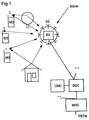
- the mobile communication system shown in FIG. 1 corresponds in its structure a well-known GSM cellular network, which consists of a large number of mobile switching centers MSC, who are networked with each other or have access to establish a fixed network PSTN. Furthermore, these are mobile switching centers MSC with at least one base station controller each Connected to BSC. Any base station controller BSC in turn enables a connection to at least a base station BS.
- a base station BS is one Radio station that connects via a radio interface to build MS mobile stations.
- FIG. 1 shows three radio connections between three mobile stations MS and a base station BS are shown.
- An operation and maintenance center OMC realizes control and Maintenance functions for the mobile network or for parts from that.
- the functionality of this structure is on other cellular networks or devices for wireless subscriber connection (i.e. the remote stations of the base station are stationary) transferable in which the invention are used can.
- the connections between the base station BS and the mobile stations MS are subject to multipath propagation caused by Reflections, for example, on buildings or plantings in addition to the direct propagation path. If one assumes a movement of the mobile stations MS, then leads the multipath propagation together with influences of Interferers that the receiving base station BS the signal components of the different propagation paths overlaying a subscriber signal as a function of time. Farther it is assumed that the subscriber signals differ Mobile stations MS at the receiving location for a received signal overlay.
- an antenna device AE with eight individual emitters form an adaptive antenna.
- the beam formation is determined by determining a Directional pattern performed for the downward direction.
- a network for beam shaping is exemplary in FIG two connections with transmission signals s1 and s2 are shown.
- the Connections are assigned to weight vectors w1 and w2 which are multiplied by the transmission signals s1 and s2, where the weighted transmission signals s1 and s2 superimposed in an HF part HF-T in high-frequency transmission signals converted and then via M single radiators be emitted.
- the transmission signals s1 and s2 are in same frequency channel (same transmission frequency, possibly time slot and / or code) and are only spatial separated.
- the antenna device AE By using different weight vectors w1, w2 for the different connections becomes a radiation characteristic the antenna device AE generates the one undisturbed reception of the transmission signals s1, s2 at the corresponding Positions of the mobile stations MS guaranteed.
- Prerequisite for setting the weight vectors w1, w2 is a determination of spatial parameters regarding the Transmission channels of the individual connections.
- Spatial separation of connections by beam shaping fails if the transmission channels of the individual connections cannot be separated sufficiently, ie if the main directions of incidence of the signals they produce are too close to one another at the base station BS.
- information about the spatial channel conditions of the signals and associated path attenuations is required. The same applies to the determination of favorable weight vectors w 1 , .., w k , by means of which the spatial separation of the individual connections in the downlink can be ensured.
- the spatial parameters can be represented in the form of spatial covariance matrices C.
- a very general way of describing the uplink of a transmission channel is given by the spatial incident power density A k ( ⁇ , ⁇ ) averaged over the fast fading, the azimuth angle being denoted by ⁇ and the elevation angle being denoted by ⁇ .
- the spatial covariance matrix C k is used for the spatial description of the downlink belonging to the subscriber k, that is to say the transmission channel from the base station BS to the mobile station MS. Sufficient spatial reciprocity of the direction of transmission is assumed.
- the frequencies of the downlink and uplink are at least approximately identical or lead to similar propagation conditions, so that group responses (steering vector, array response vector) in the downlink are approximately the same as those in the uplink.
- C. k - ⁇ + ⁇ - ⁇ / 2 + ⁇ / 2 A k ( ⁇ , ⁇ ) a ( ⁇ , ⁇ ) a H ( ⁇ , ⁇ ) d ⁇ d ⁇
- a ( ⁇ , ⁇ ) denotes the group response of the antenna device AE when receiving a wavefront.
- Fig. 3 shows a device that the determination of the directional characteristic makes.
- baseband transmission and analog / digital conversion are a digital signal processing device SP digitized input values of the received signals to disposal.
- These input values and other connection-specific Parameters (specified values for signal-to-noise ratio SNIR, noise component N at the mobile stations and spatial Covariance matrices C with respect to the transmission channels in Downward direction), as well as programs and data for implementation the following algorithms are in memory MEM saved.
- the device for determining the directional characteristic is arranged in a base station BS.
- interference power N k can be measured at the antenna of the k-th mobile station MS, which results from internal interference and co-channel interference from other mobile radio cells.
- the weight unit vector u k describes the shape of the directional characteristic and the power P k is a factor for evaluating the shape of each weight vector w k .
- the division reduces the computing effort to a great extent. This divides the complicated beam shaping problem into smaller individual problems, each of which is manageable.
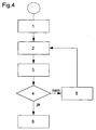
- step 4 shows a flowchart of the procedure for determining the directional characteristic, in step 1 the spatial covariance matrix C k , the signal-to-noise ratio SNIR k and the noise component N k are specified individually in step 1.
- the values SNIR k and N k are signaled by the mobile stations MS, the spatial covariance matrix C k is calculated, for example, according to patent application DE 197 37 365.
- the signal-to-noise ratios to be observed SNIR k can alternatively also be fixed across cells or networks.
- the downward transmission power P is formally set to infinity.
- step 6 the weight vectors w k are output for subsequent beam shaping.
- the rework procedure is more detailed with reference to FIG. 5 shown.
- the minimization of the cost function f i (u i ) therefore presents itself as a generalized eigenvalue problem, since the quotient in (15) is minimized by the dominant generalized eigenvector u sim; (A i , B i ) of the matrix pair (A i , B i ) becomes.
- the calculation of the dominant generalized eigenvector u ⁇ (A i , B i ) is step 14 in FIG. 5.
- the matrix B i can always be inverted, so that the generalized eigenvalue problem (15) merges into a (regular) eigenvalue problem.
- the smallest value of the cost function determines the best index iopt.
- the original weight unit vector u iopt is replaced by the improved weight unit vector u iopt (step 16).
- the rework procedure can also be applied to the weight unit vectors u k calculated in the initialization procedure if the power calculation for these vectors has failed.
Landscapes
- Engineering & Computer Science (AREA)
- Computer Networks & Wireless Communication (AREA)
- Signal Processing (AREA)
- Mobile Radio Communication Systems (AREA)
Abstract
- ein verbindungsspezifischer Gewichtseinheitsvektor für zumindest eine Verbindung bestimmt, der die Form der Richtcharakteristik beschreibt, wobei der verbindungsspezifische Gewichtseinheitsvektor einer Länge eins derart ermittelt wird, daß dessen Verwendung die durch diesen Gewichtseinheitsvektor erzeugte Empfangsleistung an der dieser Verbindung zugeordneten weiteren Funkstation maximiert,
- eine den Gewichtseinheitsvektor bewertende verbindungsspezifische Leistung für die Verbindung bestimmt, die bei der empfangenden Funkstation zu vorgegebenen Übertragungsbedingungen führt,
- ein individueller Gewichtsvektor durch Verknüpfung des Gewichtseinheitsvektors mit der Leistung bestimmt,
- Sendesignale mit dem Gewichtsvektor zu einzelstrahlerindividuellen Sendesignalen gewichtet, und
- die einzelstrahlerindividuellen Sendesignale über die Einzelstrahler abgestrahlt.
Description
- ein verbindungsspezifischer Gewichtseinheitsvektor für zumindest eine Verbindung bestimmt, der die Form der Richtcharakteristik beschreibt,
- eine den Gewichtseinheitsvektor bewertende verbindungsspezifische Leistung für die Verbindung bestimmt, die bei der empfangenden Funkstation zu vorgegebenen Übertragungsbedingungen führt, wobei der verbindungsspezifische Gewichtseinheitsvektor einer Länge eins derart ermittelt wird, daß dessen Verwendung die durch diesen Gewichtseinheitsvektor erzeugte Empfangsleistung an der dieser Verbindung zugeordneten weiteren Funkstation maximiert,
- ein individueller Gewichtsvektor durch Verknüpfung des Gewichtseinheitsvektors mit der Leistung bestimmt,
- Sendesignale mit dem Gewichtsvektor zu einzelstrahlerindividuellen Sendesignalen gewichtet, und
- die einzelstrahlerindividuellen Sendesignale über die Einzelstrahler abgestrahlt.
- Fig. 1
- eine schematische Darstellung eines Mobil-Kommunikationssystems,
- Fig. 2
- eine schematische Darstellung eines Strahlformungsnetzwerks,
- Fig. 3
- eine schematische Darstellung einer Funkstation,
- Fig. 4
- ein Ablaufdiagramm eines ersten Ausführungsbeispiels, und
- Fig. 5
- ein Ablaufdiagramm einer Nachbesserungsprozedur.

- die Abwärtssendeleistung an der Antenneneinrichtung AE der Basisstation BS minimiert wird, und
- an den Mobilstationen MS der K Teilnehmer der Störabstand SNIRk nicht überschritten wird.
minimiere
daß

- die Güte der bereits gefunden Lösung für die Gewichtsvektoren wk (Güte ausreichend),
- die Anzahl der bereits durchlaufenen Schleifen der Nachbesserung (z.B. Anzahl > 3), oder
- die Änderung der Abwärtssendeleistung P seit dem letzten Durchlauf (z.B. ΔP/P < 1 dB).
minimiere {∥Ψ -1∥ s } für alle uk mit den K Nebenbedingungen, daß

Claims (20)
- Verfahren zur Bestimmung einer Richtcharakteristik einer Funkstation (BS) mit einer Antenneneinrichtung (AE) für Funkverbindungen zu weiteren Funkstationen (MS),
wobei die Antenneneinrichtung (AE) aus mehreren Einzelstrahlern (1, 2,..M) besteht, über die Sendesignale (txm) entsprechend einer in Form und Leistung ausgeprägten Richtcharakteristik abgestrahlt werden, bei demein verbindungsspezifischer Gewichtseinheitsvektor (uk) für zumindest eine Verbindung bestimmt wird, der die Form der Richtcharakteristik beschreibt, wobei der verbindungsspezifische Gewichtseinheitsvektor (uk) einer Länge eins derart ermittelt wird, daß dessen Verwendung die durch diesen Gewichtseinheitsvektor (uk) erzeugte Empfangsleistung (Skk) an der dieser Verbindung zugeordneten weiteren Funkstation (MS) maximiert,eine den Gewichtseinheitsvektor (uk) bewertende verbindungsspezifische Leistung (Pk) für die Verbindung bestimmt wird, die bei der empfangenden Funkstation (MS) zu vorgegebenen Übertragungsbedingungen (SNIRk) führt,ein individueller Gewichtsvektor (wk) durch Verknüpfung des Gewichtseinheitsvektors (uk) mit der Leistung (Pk) bestimmt wird,Sendesignale (tx) mit dem Gewichtsvektor (wk) zu einzelstrahlerindividuellen Sendesignalen (txm) gewichtet werden, unddie einzelstrahlerindividuellen Sendesignale (txm) über die Einzelstrahler (1, 2,..M) abgestrahlt werden. - Verfahren nach Anspruch 1, bei dem die Bestimmung der verbindungsspezifischen Sendeleistungen (P1..Pk) durch Lösung eines linearen Gleichungssystems durchgeführt wird, wobei im zeitlichen Mittel die an der Antenneneinrichtung (AE) abgestrahlte Gesamtsendeleistung (P) minimal ist.
- Verfahren nach Anspruch 1 oder 2, bei demdie Bestimmung von Gewichtsvektoren (wk) für mehrere Verbindungen durchgeführt wird, wobei die verbindungsindividuellen Leistungen (Pk) derart berechnet werden, daß für alle Verbindungen individuelle vorgegebene Übertragungsbedingungen (SNIRk) eingehalten werden.
- Verfahren nach einem der Ansprüche 1 bis 3, bei demverbindungsspezifische Kanalparameter in Form räumlicher Kovarianzmatrizen oder in Form von Parametern, aus denen sich die verbindungsspezifischen räumlichen Kovarianzmatrizen berechnen lassen vorliegen, undein verbindungsspezifischer Einheitsvektor (uk) auf die Weise ermittelt wird, daß ein dominanter Eigenvektor der dieser Verbindung zugeordneten räumlichen Kovarianzmatrix (Ck) berechnet wird, und dieser Eigenvektor auf die Länge eins normiert wird.
- Verfahren nach einem der vorherigen Ansprüche, bei demSchätzwerte für die verbindungsspezifischen Kanalparameter aus an der Funkstation (BS) empfangenen Signalen abgeleitet werden.
- Verfahren nach einem der vorherigen Ansprüche, bei demdie vorgegeben Übertragungsbedingungen durch den Wert eines Störabstands (SNIRk) und/oder eines Rauschpegels (Nk) bei den empfangenden Funkstationen (MS) definiert sind.
- Verfahren nach einem der vorherigen Ansprüche, bei demdie Bestimmung der Gewichtsvektoren (wk) für mehrere Verbindungen derart durchgeführt wird, daß die Nutzempfangsleistungen (Sk) bei den empfangenden Funkstationen (MS) im Vergleich zum Störpegel (I, N) maximiert werden.
- Verfahren nach einem der vorherigen Ansprüche, bei demSchätzwerte für den Gewichtseinheitsvektor (uk) aus von der Funkstation (BS) empfangenen Signalen abgeleitet werden.
- Verfahren nach 8, bei demder Gewichtseinheitsvektor (uk) mit einem dominanten Eigenvektor einer der Verbindung zugeordneten räumlichen Kovarianzmatrix (Ck) gleichgesetzt wird.
- Verfahren nach Anspruch 8, bei demder Gewichtseinheitsvektor (uk) mit einem dominanten verallgemeinerten Eigenvektor eines Matrixpaares aus einer der Verbindung zugeordneten räumlichen Kovarianzmatrix (Ck) undeiner der Verbindung zugeordneten räumlichen Störkovarianzmatrix (
C k) gleichgesetzt wird. - Verfahren nach Anspruch 9 und 10, bei demder Gewichtseinheitsvektor (uk) ausgewählt wird, der die geringere Leistung (Pk) für die Verbindung benötigt.
- Verfahren nach einem der vorherigen Ansprüche, bei demdie Leistungen (Pk) nach folgendem Gleichungssystem:berechnet werden, wobei mit Ck verbindungsindividuelle räumliche Kovarianzmatrizen beschrieben werden.

- Verfahren nach einem der vorherigen Ansprüche, bei demnach Bestimmung der Gewichtsvektoren (wk) zumindest ein Durchlauf einer Nachbesserungsprozedur durchgeführt wird,
wobei nur ein einziger Gewichtseinheitsvektor (uk) korrigiert wird. - Verfahren nach Anspruch 13, bei demdie Nachbesserungsprozedur abgebrochen wird, sobald ein Durchlauf eine Verringerung der Leistung (Pk) erzielt, die kleiner einem Schwellwert ist.
- Verfahren nach einem der vorherigen Ansprüche, bei demverbindungsspezifische Ersatzgewichtsvektoren durch die Multiplikation von verbindungsspezifischen Ersatzeinheitsvektoren und verbindungsspezifischen Ersatzübertragungsfaktoren erzeugt werden,ein verbindungsspezifischer Ersatzeinheitsvektor derart ermittelt wird, daß dessen Verwendung als Gewichtsvektor das Verhältnis der durch diesen Gewichtsvektor an der dieser Verbindung zugeordneten weiteren Funkstation (MS) erzeugten Empfangsleistung (Skk) und der Summe der an den weiteren Funkstationen (MS) erzeugten Empfangsleistungen maximiert,der Ersatzeinheitsvektor auf die Länge eins normiert wird,die verbindungsspezifischen Ersatzübertragungsfaktoren in der Weise bestimmt werden, daß im zeitlichen Mittel sowohl die an der Antenneneinrichtung abgestrahlte Ersatzsendeleistung minimal ist, als auch an keiner der weiteren Funkstationen (MS) ein verbindungsspezifischer Störabstand (SNIR1..SNIRK) unterschritten wird, wobei die verbindungsspezifischen Ersatzeinheitsvektoren konstant gehalten werden, und
falls die Ersatzsendeleistung kleiner als die Sendeleistung (P) ist, die Sendeleistung (P), die verbindungsspezifischen Einheitsvektoren (u1..uK) und die verbindungsspezifischen Übertragungsfaktoren (v1..vK) durch die Ersatzsendeleistung, die verbindungsspezifischen Ersatzeinheitsvektoren bzw. die verbindungsspezifischen Ersatzübertragungsfaktoren ersetzt werden. - Verfahren nach einem der vorherigen Ansprüche, bei demeine Nachbesserungsprozedur durchgeführt wird, bei der eine bestimmte Verbindung (k) ausgewählt wird, und sowohl neue verbindungsspezifische Übertragungsfaktoren als auch der der ausgewählten Verbindung (k) zugeordnete neue verbindungsspezifische Einheitsvektor in der Weise bestimmt werden, daß im zeitlichen Mittel sowohl die an der Antenneneinrichtung (AE) abgestrahlte neue Sendeleistung minimal ist, als auch an keiner der weiteren Funkstationen (MS) ein verbindungsspezifischer Störabstand (SNIR1..SNIRK) unterschritten wird, wobei nur die nicht ausgewählten verbindungsspezifischen Einheitsvektoren konstant gehalten werden,der neue verbindungsspezifische Einheitsvektor auf die Länge eins normiert wird, undfalls die neue Sendeleistung kleiner als die Sendeleistung (P) ist, die Sendeleistung (P), der ausgewählte verbindungsspezifische Einheitsvektor (uk) und die verbindungsspezifischen Übertragungsfaktoren (v1..vK) durch die neue Sendeleistung, den ausgewählten neuen verbindungsspezifischen Einheitsvektor bzw. die neuen verbindungsspezifischen Übertragungsfaktoren ersetzt werden.
- Verfahren nach Anspruch 16, bei demzur Gewinnung des neuen verbindungsspezifischen Einheitsvektors ein verallgemeinertes Eigenwertproblem gelöst wird oder alternativ ein lineares Gleichungssystem und anschließend ein Eigenwertproblem gelöst werden, unddie Bestimmung der neuen verbindungsspezifischen Ersatzübertragungsfaktoren durch die Lösung eines linearen Gleichungssystems erfolgt.
- Verfahren nach einem der Ansprüche 16 oder 17, bei demeine Verbesserungsiteration auf die Weise durchgeführt wird, daß genausoviele Nachbesserungsprozeduren separat ausgeführt werden, wie Verbindungen existieren, wobei im ersten Schritt jeder Nachbesserungsprozedur eine andere Verbindung (k) ausgewählt wird, unddie Ersetzung der Sendeleistung (P), der Übertragungsfaktoren (v1..vK) und eines Einheitsvektors (uk) abschließend nur für diejenige Nachbesserungsprozedur durchgeführt wird, die die niedrigste neue Sendeleistung ergeben hat.
- Verfahren nach einem der Ansprüche 16 bis 18, bei demkeine Nachbesserungsprozedur mehr durchgeführt wird, sobald sich eine Sendeleistung ergibt, die sich unterhalb eines vorbestimmten Schwellwerts befindet.
- Funkstation,mit einer Antenneneinrichtung (AE), wobei die Antenneneinrichtung (AE) aus mehreren Einzelstrahlern (1, 2, .. M) besteht, über die Sendesignale (txm) entsprechend einer in Form und Leistung ausgeprägten Richtcharakteristik abgestrahlt werden,mit Signalverarbeitungseinrichtung (SP) zumBestimmen eines verbindungsspezifischen Gewichtseinheitsvektors (uk) für zumindest eine Verbindung, der die Form der Richtcharakteristik beschreibt, wobei der verbindungsspezifische Gewichtseinheitsvektor (uk) einer Länge eins derart ermittelt wird, daß dessen Verwendung die durch diesen Gewichtseinheitsvektor (uk) erzeugte Empfangsleistung (Skk) an der dieser Verbindung zugeordneten weiteren Funkstation (MS) maximiert,Bestimmen einer den Gewichtseinheitsvektor (uk) bewertenden verbindungsspezifischen Leistung (Pk) für die Verbindung, die bei der empfangenden Funkstation (MS) zu vorgegebenen Übertragungsbedingungen (SNIRk) führt,Bestimmen eines individuellen Gewichtsvektors (wk) durch Verknüpfung des Gewichtseinheitsvektors (uk) mit der Leistung (Pk),mit einer Übertragungseinrichtung (UE) zumWichten der Sendesignale (tx) mit dem Gewichtsvektor (wk) zu einzelstrahlerindividuellen Sendesignalen (txm), die über die Einzelstrahler (1, 2,..M) abgestrahlt werden.
Applications Claiming Priority (2)
| Application Number | Priority Date | Filing Date | Title |
|---|---|---|---|
| DE19737822 | 1997-08-29 | ||
| DE19737822 | 1997-08-29 |
Publications (2)
| Publication Number | Publication Date |
|---|---|
| EP0899813A2 true EP0899813A2 (de) | 1999-03-03 |
| EP0899813A3 EP0899813A3 (de) | 2000-11-08 |
Family
ID=7840640
Family Applications (1)
| Application Number | Title | Priority Date | Filing Date |
|---|---|---|---|
| EP98114987A Withdrawn EP0899813A3 (de) | 1997-08-29 | 1998-08-11 | Verfahren zur Bestimmung einer Richtcharakteristik einer Funkstation und eine derartige Funkstation |
Country Status (1)
| Country | Link |
|---|---|
| EP (1) | EP0899813A3 (de) |
Cited By (1)
| Publication number | Priority date | Publication date | Assignee | Title |
|---|---|---|---|---|
| DE10203593C1 (de) * | 2002-01-23 | 2003-10-02 | Siemens Ag | Verfahren zur leistungsoptimierten Strahlformung eines einer Basisstation zugehörigen Antennenarrays für zellulare Mobilfunksysteme im Downlink-Kanal |
Family Cites Families (3)
| Publication number | Priority date | Publication date | Assignee | Title |
|---|---|---|---|---|
| US5515378A (en) * | 1991-12-12 | 1996-05-07 | Arraycomm, Inc. | Spatial division multiple access wireless communication systems |
| US6101399A (en) * | 1995-02-22 | 2000-08-08 | The Board Of Trustees Of The Leland Stanford Jr. University | Adaptive beam forming for transmitter operation in a wireless communication system |
| EP0899896A1 (de) * | 1997-08-27 | 1999-03-03 | Siemens Aktiengesellschaft | Verfahren und Einrichtung zur Schätzung räumlicher Parameter von Überstragungskanälen |
-
1998
- 1998-08-11 EP EP98114987A patent/EP0899813A3/de not_active Withdrawn
Cited By (1)
| Publication number | Priority date | Publication date | Assignee | Title |
|---|---|---|---|---|
| DE10203593C1 (de) * | 2002-01-23 | 2003-10-02 | Siemens Ag | Verfahren zur leistungsoptimierten Strahlformung eines einer Basisstation zugehörigen Antennenarrays für zellulare Mobilfunksysteme im Downlink-Kanal |
Also Published As
| Publication number | Publication date |
|---|---|
| EP0899813A3 (de) | 2000-11-08 |
Similar Documents
| Publication | Publication Date | Title |
|---|---|---|
| EP1166393B1 (de) | Verfahren und vorrichtung zur strahlformung | |
| DE60028838T2 (de) | Verfahren, vorrichtungen und telekommunikationsnetzwerk zum regeln der antennengewichte eines transceivers | |
| DE602004012136T2 (de) | Verfahren und vorrichtung für ein mehrstrahl-antennensystem | |
| DE69731978T2 (de) | Verfahren und vorrichtung zur gerichteten funkübertragung | |
| DE19803188B4 (de) | Verfahren und Basisstation zur Datenübertragung in einem Funk-Kommunikationssystem | |
| DE69937268T2 (de) | Funkkommunikationssystem mit einer Raum-Zeit-Architektur unter Verwendung von Multielementantennen sowohl beim Sender als auch beim Empfänger | |
| DE60307973T2 (de) | Durchsatzverbesserung für ein Funksystem mit Multiplexzugriff, das mit SDMA kombiniert ist | |
| DE69836530T2 (de) | Adaptive gruppenantenne | |
| DE69835623T2 (de) | Verfahren und einrichtung für richtfunkkommunikation | |
| DE202005022049U1 (de) | System und Vorrichtung für Rahmenformate für den Austausch von MIMO-Kanalmessungen | |
| EP0899896A1 (de) | Verfahren und Einrichtung zur Schätzung räumlicher Parameter von Überstragungskanälen | |
| DE60118280T2 (de) | Funkanlage, die zur Echtzeitveränderung der Antennenrichtwirkung fähig ist, und für die Funkanlage verwendete Dopplerfrequenzschätzschaltung | |
| DE10026077A1 (de) | Strahlformungsverfahren | |
| DE60128999T2 (de) | Diversitätsübertragung | |
| EP1224749B1 (de) | Strahlformung in einem funk-kommunikationssystem | |
| DE602004003873T2 (de) | Verfahren zur Optimierung der Sende-Kovarianz in drahtlosen Verbindungen mit mehreren Antennen | |
| EP1336223B1 (de) | Verfahren und vorrichtung zur feedback- übertragung in einem funk- kommunikationssystem | |
| EP2393217B1 (de) | Verfahren zur Kanalschätzung und zugehöriges Funkkommunikationssystem | |
| EP1284056A1 (de) | Verfahren und vorrichtung zum auswerten eines uplink-funksignals | |
| DE102020101300A1 (de) | Vorrichtung und Verfahren für eine ein Strahltraining beinhaltende drahtlose Kommunikation | |
| WO2004025873A2 (de) | Verfahren zur signalübertragung in einem funk-kommunikationssystem | |
| WO2005025086A1 (de) | Verfahren zum übertragen von signalen in einem funkkommunikationssystem sowie entsprechende sendestation und empfangsstation | |
| DE10394345T5 (de) | Wiederholtes Paging aus einer Wireless-Daten-Basisstation mit einem intelligenten Antennensystem | |
| DE10394344T5 (de) | Nicht-gerichtetes Senden aus einer Wireless-Daten-Basisstation mit einem intelligenten Antennensystem | |
| EP1468507B1 (de) | Verfahren zur leistungsoptimierten strahlformung eines einer basisstation zugehörigen antennenarrays für zellulare mobilfunksysteme im downlink-kanal |
Legal Events
| Date | Code | Title | Description |
|---|---|---|---|
| PUAI | Public reference made under article 153(3) epc to a published international application that has entered the european phase |
Free format text: ORIGINAL CODE: 0009012 |
|
| AK | Designated contracting states |
Kind code of ref document: A2 Designated state(s): DE FR GB IT |
|
| AX | Request for extension of the european patent |
Free format text: AL;LT;LV;MK;RO;SI |
|
| PUAL | Search report despatched |
Free format text: ORIGINAL CODE: 0009013 |
|
| AK | Designated contracting states |
Kind code of ref document: A3 Designated state(s): AT BE CH CY DE DK ES FI FR GB GR IE IT LI LU MC NL PT SE |
|
| AX | Request for extension of the european patent |
Free format text: AL;LT;LV;MK;RO;SI |
|
| 17P | Request for examination filed |
Effective date: 20001004 |
|
| AKX | Designation fees paid |
Free format text: DE FR GB IT |
|
| STAA | Information on the status of an ep patent application or granted ep patent |
Free format text: STATUS: THE APPLICATION IS DEEMED TO BE WITHDRAWN |
|
| 18D | Application deemed to be withdrawn |
Effective date: 20040302 |