EP0899495B1 - Kupplungsvorrichtung für Rohre - Google Patents
Kupplungsvorrichtung für Rohre Download PDFInfo
- Publication number
- EP0899495B1 EP0899495B1 EP98115984A EP98115984A EP0899495B1 EP 0899495 B1 EP0899495 B1 EP 0899495B1 EP 98115984 A EP98115984 A EP 98115984A EP 98115984 A EP98115984 A EP 98115984A EP 0899495 B1 EP0899495 B1 EP 0899495B1
- Authority
- EP
- European Patent Office
- Prior art keywords
- press ring
- peripheral face
- space
- elastic seal
- ring
- Prior art date
- Legal status (The legal status is an assumption and is not a legal conclusion. Google has not performed a legal analysis and makes no representation as to the accuracy of the status listed.)
- Expired - Lifetime
Links
- 230000002093 peripheral effect Effects 0.000 claims description 141
- 238000003825 pressing Methods 0.000 claims description 95
- 238000003780 insertion Methods 0.000 claims description 77
- 230000037431 insertion Effects 0.000 claims description 68
- 230000007246 mechanism Effects 0.000 claims description 14
- 229920003002 synthetic resin Polymers 0.000 claims description 14
- 239000000057 synthetic resin Substances 0.000 claims description 14
- 230000004044 response Effects 0.000 claims description 11
- 238000007789 sealing Methods 0.000 claims description 7
- 230000006835 compression Effects 0.000 claims description 6
- 238000007906 compression Methods 0.000 claims description 6
- 238000012423 maintenance Methods 0.000 claims description 6
- 238000009877 rendering Methods 0.000 claims description 2
- 238000010276 construction Methods 0.000 description 32
- 238000006073 displacement reaction Methods 0.000 description 8
- 239000012530 fluid Substances 0.000 description 7
- 238000006243 chemical reaction Methods 0.000 description 5
- 230000009467 reduction Effects 0.000 description 5
- XLYOFNOQVPJJNP-UHFFFAOYSA-N water Substances O XLYOFNOQVPJJNP-UHFFFAOYSA-N 0.000 description 5
- 229910001018 Cast iron Inorganic materials 0.000 description 4
- 229910052751 metal Inorganic materials 0.000 description 4
- 239000002184 metal Substances 0.000 description 4
- 230000004048 modification Effects 0.000 description 4
- 238000012986 modification Methods 0.000 description 4
- 230000000717 retained effect Effects 0.000 description 4
- 238000010008 shearing Methods 0.000 description 4
- 239000010935 stainless steel Substances 0.000 description 4
- 229910001220 stainless steel Inorganic materials 0.000 description 4
- 229920003051 synthetic elastomer Polymers 0.000 description 4
- 239000005061 synthetic rubber Substances 0.000 description 4
- 230000005489 elastic deformation Effects 0.000 description 3
- 238000004519 manufacturing process Methods 0.000 description 3
- 230000001105 regulatory effect Effects 0.000 description 3
- 229920003048 styrene butadiene rubber Polymers 0.000 description 3
- 229930182556 Polyacetal Natural products 0.000 description 2
- 239000000853 adhesive Substances 0.000 description 2
- 230000008901 benefit Effects 0.000 description 2
- 229920006324 polyoxymethylene Polymers 0.000 description 2
- 230000003068 static effect Effects 0.000 description 2
- 229910000838 Al alloy Inorganic materials 0.000 description 1
- JOYRKODLDBILNP-UHFFFAOYSA-N Ethyl urethane Chemical compound CCOC(N)=O JOYRKODLDBILNP-UHFFFAOYSA-N 0.000 description 1
- 230000033228 biological regulation Effects 0.000 description 1
- 230000008859 change Effects 0.000 description 1
- 230000007547 defect Effects 0.000 description 1
- 239000013013 elastic material Substances 0.000 description 1
- 238000010348 incorporation Methods 0.000 description 1
- 230000014759 maintenance of location Effects 0.000 description 1
- 239000000463 material Substances 0.000 description 1
- 238000000034 method Methods 0.000 description 1
- 230000002265 prevention Effects 0.000 description 1
Images

Classifications
-
- F—MECHANICAL ENGINEERING; LIGHTING; HEATING; WEAPONS; BLASTING
- F16—ENGINEERING ELEMENTS AND UNITS; GENERAL MEASURES FOR PRODUCING AND MAINTAINING EFFECTIVE FUNCTIONING OF MACHINES OR INSTALLATIONS; THERMAL INSULATION IN GENERAL
- F16L—PIPES; JOINTS OR FITTINGS FOR PIPES; SUPPORTS FOR PIPES, CABLES OR PROTECTIVE TUBING; MEANS FOR THERMAL INSULATION IN GENERAL
- F16L21/00—Joints with sleeve or socket
- F16L21/08—Joints with sleeve or socket with additional locking means
Definitions
- the present invention relates to a pipe connecting apparatus for connecting a first pipe member having an inner peripheral face and an axis with a second pipe member inserted into the first pipe member. More particularly, the invention relates to a pipe connecting apparatus for use in a pipe system of a fluid transport pipe such as a water pipe installed under the ground in order to prevent inadvertent withdrawal of the second pipe member inserted into and connected with the first pipe member by an external tensile force in the axial direction of the pipe which may be applied to the system due to an earthquake, differential settlement or the like.
- a fluid transport pipe such as a water pipe installed under the ground
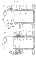
- a conventional pipe connecting apparatus as shown in Figs. 12 and 13, over an insertion pipe portion 51 (an example of the second pipe member) inserted into and connected with a receiver pipe portion 50 (an example of the first pipe member), there are fitted an elastic seal 52 capable of sealing between an inner peripheral face of the receiver pipe portion 50 and an outer peripheral face of the insertion pipe portion 51 and a press ring 53 having a substantially C-shaped configuration as seen in the axial direction X of the pipe, the press ring 53 being capable of compressing the elastic seal 52 from the axial direction X and also of elastically deformable to be reduced in its diameter.
- a first fastener means 54 is provided for fastening the press ring 53 and the receiver pipe portion 50 together in the pipe axial direction X.
- a retainer ring 55 having a substantially C-shaped configuration as seen from the pipe axial direction and capable of being elastically deformed to be reduced in its diameter until the ring 55 is pressed against the outer peripheral face of the insertion pipe portion 51.
- the press ring 53 is provided as the C-shaped ring having one cutout portion in the periphery thereof which is capable of elastically deformable to be reduced in its diameter.
- This press ring 53 integrally includes, at opposed free peripheral ends thereof, a pair of connecting pieces 53A opposed to each other in a direction substantially normal to the pipe axial direction X (i.e. along the peripheral direction of the pipe). And, across these connecting pieces 53A, there is provided a second fastener means 56 which is fastened in said normal direction to elastically deform the press ring 53 in the diameter-reducing direction, thus elastically deforming the retainer ring 55 in the diameter-reducing direction.
- first connecting projections 50A At a plurality of peripheral portions at an end of the outer peripheral face of the receiver pipe portion 50, there are integrally formed first connecting projections 50A.
- second connecting projections 53B At corresponding plural peripheral portions in the outer peripheral face of the press ring 53, there are integrally formed second connecting projections 53B.
- the first fastener means 54 described above comprises plural sets of T-shaped bolts 54A and nuts 54B fitted across these respective paired connecting projections 50A, 53B of the receiver pipe portion 50 and the press ring 53.
- the second fastener means 56 comprises a pair of a bolt 56A and a nut 56 which are inserted and fitted across the opposed connecting pieces 53A of the press ring 53 described above.
- an inner peripheral face 53a of the press ring 53 includes a tapered face adapted for further pressing the retainer ring 55 against the outer peripheral face of the insertion pipe portion 51 in response to a possible mutual withdrawal displacement between the receiver pipe portion 50 and the insertion pipe portion 51.
- the press ring 53 which is still in a diameter-expanded condition and supporting the retainer ring 55 will be fitted over the insertion pipe portion 51 which was inserted in advance into the receiver pipe portion 50.
- the second connecting projections 53B of the press ring 53 and the first connecting projections 50A of the receiver pipe portion 50 retaining the elastic seal 52 therein will be temporarily connected and loosely fastened together.
- the insertion pipe portion 51 will be inserted by a predetermined length into the receiver pipe portion 50 through the retainer ring 55 and the elastic seal 52 retained to the inner peripheral face of the press ring 53.
- the bolts 54A and the nuts 54B of the first fastener means 54 will be fastened so as to fixedly connect the first connecting projections 50A of the receiver pipe portion 50 and the second connecting projections 53B of the press ring 53.
- the elastic seal 52 will be compressed in the pipe axial direction X so as to seal between the inner peripheral face of the receiver pipe portion 50 and the outer peripheral face of the insertion pipe portion 51.
- the conventional pipe connecting apparatus requires the fastening operation of the first fastener means 54 in the pipe axial direction X for compressing the elastic seal 52 and the further fastening operation of the second fastener means 56 in the pipe radial direction for elastically compressing the retainer ring 55 for the bite-in engagement.
- the assembly operation of the conventional apparatus is troublesome as requiring many steps.
- the apparatus requires a significant number of components for providing these fastener means; and also, in connection with this requirement, it is also necessary to form a number of connecting projections and bolt-inserting holes in the receiver pipe portion 50 and the press ring 53, respectively. This tends to result in complexity of the entire construction as well as increase in the manufacture cost.
- the retainer ring 55 will bite into the outer peripheral face of the insertion pipe portion 51. Then, if the first fastener means 54 is fastened under this condition, the resultant mutual approaching displacement between the press ring 53 and the receiver pipe portion 50 will cause displacement of the insertion pipe portion 51 together with the press ring 53 via the retainer ring 55, so that the pipe portion 51 will be inserted further into the receiver pipe portion 50, thus leading to a change in the insertion length of this insertion pipe portion 51 into the receiver pipe portion 50. Moreover, if the leading end of the insertion pipe portion 51 comes into abutment against a projection 50B on the inner peripheral face of the receiver pipe portion 50, any further fastening operation will be disabled, thus inviting sealing defect due to insufficient compression of the elastic seal 2.
- a primary object of the present invention is to provide a pipe connecting apparatus which allows the connection between the first pipe member and the second pipe member inserted therein to be effected reliably and efficiently for providing reliable sealed connection therebetween with maximally maintaining the originally set insertion length of the latter relative to the former and which also allows simple construction and reduction in its manufacture costs through reduction in the number of components needed for constructing the apparatus.
- the apparatus comprises the features of claim 1.
- the second pipe member will be inserted into the first pipe member by a predetermined length and the press ring will be fastened in the axial direction toward the elastic seal which is disposed within the gap between the inner peripheral face of the first pipe member and the outer peripheral face of the second pipe member.
- the press ring and the first pipe member will be axially moved closer to each other.
- the operation for compressing the elastic seal into the sealed condition and the subsequent operation for pressing the retainer ring against (or into) the outer peripheral face of the insertion pipe portion may take place sequentially only by the continuation of the single fastening operation for pressing the press ring against the elastic seal. That is, during the former half of the fastening operation, i. e. while the press ring is being moved relative to the first pipe member for compressing the elastic seal, the retainer member still maintains its released condition, so that the retainer member will not be pressed against the outer peripheral face of the second pipe member. Therefore, during this former half of the fastening operation, there will occur no inadvertent movement of the second pipe member relative to the first pipe member by the press ring via the retainer member.
- the invention has fully achieved its intended object of providing a pipe connecting apparatus which allows the connection between the first pipe member and the second pipe member inserted therein to be effected reliably and efficiently for providing reliable sealed connection therebetween with maximally maintaining the originally set insertion length of the latter relative to the former and which also allows simple construction and reduction in its manufacture costs through reduction in the number of components needed for constructing the apparatus, in comparison with the conventional apparatus.
- the sequentially operative mechanism includes an intermediate pressing element having a face to come into contact with the elastic seal and a space-regulating element for maintaining an axial opposing space between the press ring and the intermediate pressing element within a range allowing the released condition of the retainer member; and the space-regulating element releases the space maintenance in said second state and allows the retainer member to be switched over to the locked condition in association with the axial movement of the retainer member relative to the press ring.
- the space-regulating element adapted for maintaining the axial opposing space between the intermediate pressing element and the press ring functions to maintain the retainer member under its initial non-radially compressed condition or the condition not to bite into the outer peripheral face of the second pipe member.
- the space-regulating element releases its space maintenance. So that, in association of further fastening operation, the intermediate pressing element and the press ring will start moving closer to each other in the axial direction; and with progress of this mutual approaching movement the retainer member will be pressed against the outer peripheral face of the second pipe member.
- the entire pipe connecting apparatus may be formed simple and compact, yet capable of fully achieving the intended object.
- the space-regulating element is provided as an element which can be buckled (i.e. crumple under pressure) between the press ring and the intermediate pressing element in response to the compressive force exceeding the predetermined value.
- the space-regulating element for releasing the space maintenance by the space-regulating element, the member which can be buckled by the reaction force from the elastic seal which has been compressed to the predetermined compressed condition is utilized. Therefore, the space-regulating element per se may readily be formed simple and compact, whereby the simplicity and compactness of the entire pipe connecting may be further promoted.
- the space-regulating element of the above type may comprise an element which is attached to the intermediate pressing element so as to extend axially from this intermediate pressing element toward the press ring.
- the space-regulating element and the intermediate pressing element may be handled together as one component.
- the assembly of the pipe connecting apparatus may be carried out more efficiently and easily.
- the space-regulating element includes an engaging portion for coming into elastic axial engagement with an engaged portion in the inner peripheral face of the press ring so as to check a withdrawal movement of the retainer member interposed between the space-regulating element and the inner peripheral face of the press ring.
- the space-regulating element may comprise an element which can be sheared between the press ring and the intermediate pressing element in response to the compressive force exceeding the predetermined value.
- This construction in comparison with the foregoing buckled type construction, has the advantage that the necessary collapsing of the space-regulating element in association with the realization of the predetermined compressed condition of the elastic seal by the fastening operation may take place in a more sudden and conspicuous manner. As a result, the amount of deformation in the space-regulating element until the arrival of the elastic seal at the predetermined compressed condition may be reduced, so that the reliability of the space maintaining function may be improved.
- the space-regulating element of the above-described type may be a pair of annular cylindrical portions formed and connected integrally with each other and having different diameters so as to form a stepped cross section in the initial integrally connected state.
- the connecting portion between the cylindrical portions may be sheared in response to the compressive force exceeding the predetermined value so as to allow the two elements overlapped with each other in the radial direction.
- the bordering portion i.e. the connecting portion between the two annular cylindrical portions is sheared, so that the cylindrical portions will be moved one into the other in a telescopic manner.
- the space-regulating element is provided as a cylindrical portion (made of a synthetic resin or the like) consisting of a plurality of cylindrical portions of different diameters to provide a stepped cross section.
- the space-regulating element may include a projecting portion which projects from the intermediate pressing element in the radial direction, the projecting portion supporting the press ring in the first state, the projecting portion being sheared by the press ring in response to the compressive force exceeding the predetermined value.
- the press ring may include, in its inner peripheral face, an engaging groove consisting essentially of a first engaging groove into and from which the projecting portion is engageable and disengageable in the axial direction and a second engaging groove for preventing withdrawal of the projecting portion through relative rotation in the axial direction after insertion of the projecting portion into the first engaging groove.
- the press ring and the intermediate pressing element will be rotated relative to each other about the pipe axis so as to engage the leading end of the space-regulating element into the second engaging groove, whereby the press ring and the intermediate pressing element may be connected with each other via the space-regulating element.
- the assembly operation of the press ring and the intermediate pressing element may be carried out speedily and easily.
- the engaging groove includes a resistance providing means for providing resistance against the movement of the projecting portion of the space-regulating element between the first engaging groove and the second engaging groove.
- the space-regulating element may be a headed shear pin removably inserted into a radially extending through hole defined in the intermediate pressing element from the side of the outer peripheral face, with withdrawal of the shear pin from the through hole being prevented through abutment between the retainer member adjacent the intermediate pressing element and the head of the shear pin.
- a commonly available shear pin may be employed as the space-regulating element, so that the total cost of the pipe connecting apparatus may be further reduced.
- a withdrawal movement of the shear pin inserted into the through hole of the intermediate pressing element from the side of the inner peripheral face may be prevented through utilization of the outer peripheral face of the retainer member engaged within the intermediate pressing element. In this manner, no special member dedicated to prevention of withdrawal of the shear pin is needed. As a result, the simplicity of the entire construction and the facility of the assembly operation may be further promoted.
- the projecting portion may be a pin-like element extending integrally and radially from the outer peripheral face of the retainer member, the pin-like element being axially engageable with the press ring beyond the radially extending through hole defined in the intermediate pressing element.
- the pin-like element constituting the space-regulating element and the retainer member may be handled as one integral component. Hence, the efficiency and facility of the assembly operation may be further promoted.
- the retainer member comprises a pair of arcuate members which are joined together to present an annular configuration, the pin-like element extending integrally from an outer peripheral face of each said arcuate member.
- a cam mechanism for rendering the retainer member into the locked condition in response to the relative axial movement between the retainer member and the press ring.
- the retainer member too due to its cam face formed between the press ring, will be pressed against the outer peripheral face of the second pipe member. Also, the resilient force of the elastic seal tending to push back the retainer member in the axial direction will tend to enlarge the diameter of the press ring due to this function of the cam face, there will be realized an interlocked condition between the retainer member and the press ring due to static friction therebetween, so that the press ring too will be fixed temporarily.
- the fastener means comprises a flange defining a bolt-insertion hole and provided respectively to the press ring and the first pipe member.
- the retainer member comprises a retainer ring having a C-shaped configuration as seen in the axial direction and deformable in a diameter-reducing direction, the retainer ring having an inner diameter which is larger under a zero-load condition than the outer diameter of the insertion pipe portion.
- the inserting operation of the insertion pipe portion into the retainer ring may be carried out easily. So that, the efficiency of the assembly operation of the pipe connecting apparatus may be further improved.
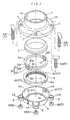
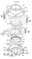
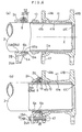
- Figs. 1-3 show a pie connecting apparatus for a fluid transport pipe system (e.g. for water pipe).
- a fluid transport pipe system e.g. for water pipe
- an insertion pipe portion 2 made of synthetic resin is inserted into and connected with a receiver pipe portion 1 made of cast iron.
- an elastic seal 3 made of synthetic rubber (e.g. styrene-butadiene rubber) capable of sealing a gap formed between an inner peripheral face 1a of the receiver pipe portion 1 and an outer peripheral face 2a of the insertion pipe portion 2 and a press ring 4 made of cast iron capable of compressing the elastic seal in a pipe axial direction X into a sealed (water-tight) condition.
- synthetic rubber e.g. styrene-butadiene rubber
- a fastener means 5 is provided for fastening the press ring 4 with the receiver pipe portion 1 in the axial direction X.
- a retainer ring 6 made of synthetic resin such as polyacetal or metal such as stainless steel. This retainer ring 6 is capable of elastic deformation in a diameter-reducing direction to bite into the outer peripheral face 2a of the insertion pipe portion 2 with a mutually approaching movement between the press ring 4 and the receiver pipe portion 1 in association with a fastening operation of the fastener means 5.
- a sequentially operative mechanism S1 which is operative to press the elastic seal 3 alone in the axial direction during a former half of the fastening operation of the fastener means 5 and also to allow the retainer ring 6 to be elastically deformed in the diameter-reducing direction to such a degree as to bite into the outer peripheral face of the insertion pipe portion 2 against the resilient force thereof during a latter half of the fastening operation of the retainer ring after the elastic seal 3 has been compressed into a predetermined compressed condition.
- the receiver pipe portion 1 integrally forms a first connecting flange 1A provided at one end the pipe portion 1 and defining a plurality of bolt-insertion holes 7 for the connection with the press ring 4 at a plurality of peripheral portions (four positions in this embodiment) thereof, a second connecting flange 1B provided at the other end of the pipe portion 1 to be fixedly connected by means of bolts and nuts with another fluid pipe device such as a fluid transport pipe (e.g. water pipe) or a sluice valve, and an annular projection 1C which comes into contact with a leading end of the inserted insertion pipe portion 2 in the axial direction X.
- a fluid transport pipe e.g. water pipe
- sluice valve e.g. sluice valve
- seal retaining portion 1b which can removably retain the elastic seal 3 in the axial direction X.
- This seal retaining portion 1b has a tapered cross section whose opening diameter increases toward the axial end.
- the press ring 4 integrally forms in the outer peripheral face thereof a plurality of connecting projections 4A at a plurality of peripheral portions (four portions in this embodiment) in an outer peripheral face thereof.
- Each connecting projection 4A defines a bolt-insertion hole 8 for connection with the first connecting flange 1A of the receiver pipe portion 1.
- an inner peripheral face 4a of this press ring 4 is provided as a tapered face having a predetermined direction. Then, when the receiver pipe portion 1 and the insertion pipe portion 2 tend to move in the withdrawing direction due to some external force (e.g.
- the tapered face comes into abutment against an outer peripheral face 6a of the retainer ring 6 which has already bitten to a certain extent into the outer peripheral face 2a of the insertion pipe portion 2, so that the face deforms the ring 6 in the diameter-reducing direction to cause the ring 6 to bite further into the outer peripheral face 2a of the insertion pipe portion 2.
- the retainer ring 6 has an inner diameter which is larger, in a non-radially reduced state, i.e. when no external force is applied thereto, than the outer diameter of the insertion pipe portion 2. Further, the outer peripheral face 6a of this retainer ring 6, except for two peripheral portions thereof where flat cut faces 6F are formed, is provided as a tapered face having the same inclination as that of the inner peripheral face 4a of the press ring 4. In addition, in the inner peripheral face of this retainer ring 6, there are formed sharp-edged retaining projections capable of radially biting into the outer peripheral face 2a of the insertion pipe portion 2.
- the fastener means 5 consists of T-shaped bolts 5A inserted through the bolt-insertion holes 7 defined in the first connecting flange 1A of the receiver pipe portion 1 and also through the bolt-insertion holes 8 defined in the connecting projections 4A of the press ring 4 and nuts 5B therefor.
- the sequentially operative means S1 includes an intermediate pressing element 9 in the form of a circular ring to be pressed against the elastic seal 3 with a displacement of the press ring 4 relative to the receiver pipe portion 1 and a space-regulating element 10 interposed between the press ring 4 and the intermediate pressing element 9 along the axial direction X.
- the intermediate pressing element 9 is made of metal such as stainless steel or synthetic resin.
- the space-regulating element 10 is made of synthetic resin such as urethane which can be buckled and collapsed under a reaction force from the elastic seal 3 which has been rendered into the predetermined compressed condition with the fastening operation of the fastener means 5.
- the press ring 4 In association with the fastening operation by the fastener means 5, the press ring 4 will be moved along the axial direction X toward the receiver pipe portion 1, so that the press ring 4 and the space-regulating element 10, the space-regulating element 10 and the intermediate pressing element 9, and the intermediate pressing element 9 and the elastic seal 3 retained within the seal retaining portion 1b come into abutment against each other, respectively. With this, first, the fastening force from the fastener means 5 will be transmitted via the press ring 4 to the space-regulating element 10.
- the space-regulating element 10 serves to maintain the opposing distance in the axial direction X between the intermediate pressing element 9 and the press ring 4 at such a distance that doe not cause the diameter-reducing deformation of the retainer ring 6. Also, when the elastic seal 3 has reached the predetermined compressed condition, the element 10 releases the space maintenance function through its own buckling deformation.
- the intermediate pressing element 9 includes a seal pressing face 9a for pressing the elastic seal 3 along the axial direction X and a ring pressing face 9b for pressing an end face 6c in the axial direction X of the retainer ring 6 toward the tapered inner peripheral face 4a of the press ring 4. Further, as shown in Fig. 1 and Fig. 3(a), in the outer peripheral face 9A of the intermediate pressing element 9 and at two portions thereof peripherally displaced by 180 degrees from each other, there are integrally formed a pair of plate-like pressure-receiving portions 9B projecting therefrom.
- the space-regulating element 10 made of synthetic resin is fixed by means of an adhesive agent or the like, with the element 10 projecting toward the pressing face 4c of the press ring 4.
- an attachment positioning means 11 which allows attachment and detachment of the pressure-receiving portions 9B of the intermediate pressing element 9 in the axial direction X and which also restricts relative rotational displacement among the press ring 4, the retainer ring 6 and the intermediate pressing element 9 when the intermediate pressing element 9 has been engaged between the tapered outer peripheral face 6a of the retainer ring 6 and the tapered inner peripheral face 4a of the press ring 4.
- This attachment positioning means 11 consists essentially of the flat cut faces 6F (extending substantially parallel with the axial direction X) formed at the two peripheral portions in the tapered outer peripheral face 6a of the retainer ring 6 in the vicinity of the inner peripheral face of the two pressure-receiving portions 9B of the intermediate pressing element 9 and of groove portions 4F formed at two peripheral portions in the inner peripheral face 4a of the press ring 4 and engaged with the outer peripheral faces of the pressure-receiving portions 9B of the intermediate pressing element 9.
- the space-regulating element 10 includes an engaging portion 10a which comes into elastic engagement along the axial direction X with an engaged portion 4d formed at an end portion in the inner peripheral face of the press ring 4 facing the groove portion 4F as the positioning means 11 so as to prevent inadvertent withdrawal of the retainer ring 6 fitted between the space-regulating element 10 and the inner peripheral face of the press ring 4.
- the opposing distance in the axial direction X between the intermediate pressing element 9 and the press ring 4 is maintained at the predetermined distance by means of the space-regulating element 10 affixed to the intermediate pressing element 9. So that, the retainer ring 6 is maintained at its original non-reduced (i.e. the large-diameter) state.
- the space-regulating element 10 made of synthetic resin will collapse due to its own buckling deformation, so as to release its space maintaining function.
- the buckling deformation of the space-regulating element 10 will be further developed, whereby the intermediate pressing element 9 and the press ring 4 begin to move closer to each other along the axial direction X.
- the retainer ring 6 will be deformed in the diameter-reducing direction against its own elastic resilience.
- the inner peripheral face 4a of the press ring 4 will radially compress the retainer ring 6 to cause its retaining projections 6b to bite into the outer peripheral face 2a of the insertion pipe portion 2.
- the space-regulating element 10 in association with its own collapsing deformation, will be forced into the gap between the inner peripheral faces of the pressure-receiving portions 9B of the intermediate pressing element 9 and the cut faces 6F of the retainer ring 6 as well as the gap between the outer peripheral faces of the pressure-receiving portions 9B of the intermediate pressing element 9 and the inner faces of the groove portions 4F of the press ring 4.
- the amount of engagement and matching engagement shape between the engaging portion 10a of the space-regulating element 10 and the engaged portion 4d of the press ring 4 may be modified in any way as long as such modification still enables un-withdrawable retention of the space-regulating element 10 within the press ring 4 while allowing insertion and withdrawal of the space-regulating element 10 to and from the press ring 4 along the axial direction X.
- the space-regulating element 10 is affixed to the intermediate pressing element 9 by means of an adhesive agent or the like. Instead, this space-regulating element 10 may be engaged and retained to the intermediate pressing element 9.
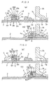
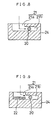
- FIG. 4 shows a pipe connecting apparatus according to a second embodiment of the present invention.
- a space-regulating element 12 employed in this embodiment presents as a whole an annular configuration.
- this element 12 has a stepped cross section consisting of a plurality (two in this particular embodiment) of cylindrical portions 12a, 12b of differing inner and outer diameters integrally interconnected with each other in the axial direction X.
- the small-diameter cylindrical portion 12b will be telescopically moved into the hollow inner space of the large-diameter cylindrical portion 12a. With this deformation accompanied by shearing, the space maintenance will be released.
- the retainer ring 6 will be compressed in its diameter against its own resilience, so that the retaining projections 6b of the retainer ring 6 will bite into the outer peripheral face 2a of the insertion pipe portion 2.
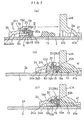
- Figs. 5-8 show a pipe connecting apparatus for a fluid transport pipe system (e.g. for water pipe).
- a fluid transport pipe system e.g. for water pipe
- an insertion pipe portion 2 made of synthetic resin is inserted into and connected with a receiver pipe portion 41 made of cast iron.
- an elastic seal 13 made of synthetic rubber (e.g. styrene-butadiene rubber) capable of sealing a gap formed between an inner peripheral face 41a of the receiver pipe portion 41 and an outer peripheral face 2a of the insertion pipe portion 2 and a press ring 24 made of cast iron capable of compressing the elastic seal in a pipe axial direction X into a sealed (water-tight) condition.
- synthetic rubber e.g. styrene-butadiene rubber
- a fastener means 5 is provided for fastening the press ring 24 with the receiver pipe portion 41 in the axial direction X.
- a retainer ring 6 made of synthetic resin such as polyacetal or metal such as stainless steel. This retainer ring 6 having a substantially C-shaped configuration, is capable of elastic deformation in a diameter-reducing direction to bite into the outer peripheral face 2a of the insertion pipe portion 2.
- a tapered cam face 24b for elastically deforming the retainer ring 6 in the diameter-reducing direction with a mutually approaching movement between the press ring 24 and the receiver pipe portion 41 in association with a fastening operation of the fastener means 5.
- a sequentially operative mechanism S2 which is operative to press the elastic seal 13 alone in the axial direction during a former half of the fastening operation of the fastener means 5 and also to allow the retainer ring 6 to be elastically deformed in the diameter-reducing direction against the resilient force thereof during a latter half of the fastening operation of the retainer ring after the elastic seal 13 has been compressed into a predetermined compressed condition.
- the receiver pipe portion 41 integrally forms a first connecting flange 41A provided at one end the pipe portion 41 and defining a plurality of bolt-insertion holes 47 for the connection with the press ring 24 at a plurality of peripheral portions (four positions in this embodiment) thereof, a second connecting flange 41B provided at the other end of the pipe portion 41 to be fixedly connected by means of bolts and nuts with another fluid pipe device such as a fluid transport pipe (e.g. water pipe) or a sluice valve, and an annular projection 41C which comes into contact with a leading end of the inserted insertion pipe portion 2 in the axial direction X.
- a fluid transport pipe e.g. water pipe
- a sluice valve e.g. water pipe
- seal retaining portion 41b which can removably retain the elastic seal 13 in the axial direction X.
- This seal retaining portion 41b has a tapered cross section whose opening diameter increases toward the axial end.
- the press ring 24 integrally forms in the outer peripheral face thereof a plurality of connecting projections 24A at a plurality of peripheral portions (four portions in this embodiment) in an outer peripheral face thereof.
- Each connecting projection 24A defines a bolt-insertion hole 28 for connection with the first connecting flange 41A of the receiver pipe portion 41.
- a cam face 24b of this press ring 24 is constructed such that when the receiver pipe portion 41 and the insertion pipe portion 2 tend to move in the withdrawing direction due to some external force (e.g.
- the cam face comes into abutment against an outer peripheral face 6a of the retainer ring 6 which has already bitten to a certain extent into the outer peripheral face 2a of the insertion pipe portion 2, so that the face deforms the ring 6 in the diameter-reducing direction to cause the ring 6 to bite further into the outer peripheral face 2a of the insertion pipe portion 2.
- the retainer ring 6 has an inner diameter which is larger, in a non-radially reduced state, i.e. when no external force is applied thereto, than the outer diameter of the insertion pipe portion 2. Further, the outer peripheral face 6a of this retainer ring 6 is provided as a tapered face having the same inclination as that of the tapered cam face 24b of the press ring 24. In addition, in the inner peripheral face of this retainer ring 6, there are formed sharp-edged retaining projections 6b capable of radially biting into the outer peripheral face 2a of the insertion pipe portion 2.
- the fastener means 5 consists of T-shaped bolts 5A inserted through the bolt-insertion holes 47 defined in the first connecting flange 41A of the receiver pipe portion 41 and also through the bolt-insertion holes 28 defined in opposition thereto in the connecting projections 24A of the press ring 24 and nuts 5B therefor.
- the sequentially operative means S2 includes an intermediate pressing element 19 in the form of a circular ring made of metal such as stainless steel or synthetic resin.
- the intermediate pressing element 19 has a first pressing face 19a for compressing the elastic seal 13 along the axial direction X with a mutually approaching displacement between the press ring 24 and the receiver pipe portion 41 and a second pressing face 19b capable of compressing the retainer ring 6 along the axial direction X toward the cam face 24b of he press ring 24.
- the sequentially operative means S2 further includes a space-regulating element 20 extending along mutually radially opposing or substantially opposing portions of the intermediate pressing element 19 and the press ring 24.
- This space-regulating element 20 functions to maintain the opposing space along the axial direction X between the cam face 24b of the press ring 24 and the second pressing face 19b of the intermediate pressing element 19 within such a range as not to elastically deform the retainer ring 6 in the diameter-reducing direction which ring is maintained under a non-biting state until the elastic seal 13 reaches the predetermined compressed condition in association with the mutually approaching movement between the press ring 24 and the receiver pipe portion 41.
- the space-regulating element 20 is sheared between the outer peripheral face of the intermediate pressing element 19 and the inner peripheral face of the press ring 24 so as to release its space maintaining state, i.e. to allow the mutually approaching movement in the axial direction X between the cam face 24b of the press ring 24 and the second pressing face 19b of the intermediate pressing element 19.
- a brim portion 19A which comes along the axial direction X into the gap between the inner peripheral face 24a of the press ring 24 and the outer peripheral face 6a of the retainer ring 6.
- Each brim portion 19A defines a radially extending through hole 19c into which a headed shear pin made of an aluminum alloy and constituting the space-regulating element 20 is removably inserted from the side of the inner peripheral face.
- each brim portion 19A is adapted to come into abutment, along the axial direction X, against a stopper face 24c formed at an inner portion of the inner peripheral face 24a of the press ring 24.
- any withdrawal movement of the shear pin 20 inserted from the side of the inner peripheral face into the through holes 19c of the brim portions 19A of the intermediate pressing element 19 may be effectively checked through abutment thereof with the flat faces 6c of the retainer ring 6 inwardly engaged with the brim portions 19A of the intermediate pressing element 19.
- engaging grooves 21 each of which includes a first engaging groove portion 21a into which the leading end of the shear pin 20 inserted into the through hole 19c of the brim portion 19A is removably engageable and a second engaging groove portion 21b into which prevents withdrawal movement of the leading end of the shear pin 20 along the axial direction X through relative rotation about the axis X with the leading end of the shear pin 20 being located at a predetermined position inside the first engaging groove portion 21a.
- the shear pins 20 will be sheared by the reaction force therefrom between the outer peripheral face of the intermediate pressing element 19 and the inner peripheral face 24a of the press ring 24, so that the shear pins release their space maintaining condition.
- the second pressing face 19b of the intermediate pressing element 19 and the cam face 24b of the press ring 24 will be moved closer to each other, in association with which the retainer ring 6 will elastically deformed in the diameter-reducing direction to bite into the outer peripheral face 2a of the insertion pipe portion 2.
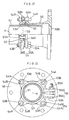
- Fig. 9 shows a modification of the engaging groove 21 of the pipe connecting apparatus described above in the third embodiment.
- a resistance providing means 22 is provided at the communicating portion between the first engaging groove portion 21a and the second engaging groove portion 21b of the engaging groove 21, for providing resistance against he movement of the leading end of the shear pin 20 constituting the space-regulating element.
- This resistance providing means 22 is formed of synthetic rubber (e.g. styrene-butadiene rubber). In operation, when elastically deformed by the pressing force from the leading end of the shear pin 20, the resistance providing means 22 allows passage of the leading end of the shear pin 20. Whereas, when the resistance providing means 22 is not subjected to a pressing force exceeding a predetermined magnitude, this prevents movement of the leading end of the shear pm 20 toward the first engaging groove portion 21a.
- synthetic rubber e.g. styrene-butadiene rubber
- Figs. 10 and 11 show a further space-regulating element relating to the fourth embodiment of the present invention.
- This element comprises a pin-like element 30 which extends integrally from the outer peripheral face of the retainer member 16 with the element 30 engaged with the engaging groove 21 of the press ring 24 through the through hole 19c of the brim portion 19A of the intermediate pressing element 19.
- the retainer member 16 consists of split ring portions 16A which may be obtained e.g. by dividing the retainer ring 6 of the third embodiment into two halves.
- split ring portions 16A and the pin-like element 30 are formed integral of e.g. synthetic resin.
- the retainer member under the zero-load condition, has a larger inner diameter than the outer diameter of the insertion pipe portion 2 and this retainer member bites into the outer periphery of the insertion pipe portion 2 only when the member receives an external force overwhelming its elastic resilience.
- the pipe connecting apparatus using this further space-regulating element relating to the fourth embodiment, when the connecting apparatus is fitted over the outer periphery of the insertion pipe portion 2, the respective split ring portions 16A, 16A will be pressed against the inner peripheral face of the press ring 24 and the pin-like elements 30 will be fitted within the engaging grooves 21 of the press ring 24.
- the split ring portions 16A, 16A will be maintained to be spaced apart from each other in the radial direction so that the retainer projections 16b thereof will not bite into the outer peripheral face of the insertion pipe portion 2. Accordingly, the press ring 24 may be readily moved in the axial direction X. Then, with application of an external force thereto, the split ring portions 16A, 16A will be moved closer to each other towards the axis X, so that they will bite into the outer peripheral face of the insertion pipe portion 2.
- the shear pins 20 constituting the space-regulating element are provided at the two mutually radially opposing or substantially opposing portions of the intermediate pressing element 19 and the inner peripheral face of the press ring 24.
- the shear pins 20 may be provided at four positions.
- the elastic seal 13 alone be compressed in the former half of the fastening operation of the fastener means 5 and also the elastic seal 13 be capable of deforming the retainer ring G into the diameter-reducing direction to bite into the outer peripheral face of the insertion pipe portion 2 in association with a further fastening operation after the elastic seal 13 has reached the predetermined compressed condition.
- the number of the space-regulating elements 20 to be distributed along the peripheral direction is not particularly limited in the present invention.
- the retainer ring 6 is provided as a C-shaped retainer ring which can be elastically deformed and reduced in its diameter along the axial direction X. Further, in the fourth embodiment, the retainer ring 6 consists of two split ring portions 16A. Still further, this retainer ring 6 may consist of more than three split ring or arc portions.
- the resistance providing means 22 for providing resistance against the movement of the leading end of the shear pin 20 as the space-regulating element 20 is provided in the form of a block member formed of synthetic rubber.
- this resistance providing means 22 may be formed of any other elastic material or member such as a plate spring or the like.
- the movement of the leading end of the shear pin 20 engaged into the second engaging groove portion 21a toward the first engaging groove portion 21a may be checked by means of a pin or the like which is removably disposed.
- the opposing distance in the axial direction X between the intermediate pressing element 9, 19 and the press ring 4, 24 is maintained at such a distance not to cause the diameter reduction of the retainer ring 6.
- the opposing distance may be maintained to such a degree to allow a limited amount of diameter-reducing deformation of the retainer ring 6 within which the retainer ring 6 will not bite into the outer peripheral face 2a of the insertion pipe portion 2.
- this is realized through collapse by buckling deformation or shearing of the element 10.
- this space-regulating element 10 it is also conceivable to adapt this space-regulating element 10 so that the element may automatically return to the space-regulating condition from the space regulation released condition in response to release of the compressive force applied to the elastic seal 3.
- this may be realized by forming the space-regulating element of material having a large elastic resilience or forming the element in a shape providing a large elastic resilience, for instance.
- the fastener means 5 consists of the bolt 5A and the nut 5B.
- the specific construction of this fastener means is not particularly limited in this invention as long as it can effectively fasten the press ring 4, 24 and the receiver pipe portion 1 together in the axial direction X.
- the fastener means may comprise a cam fastening type construction or the like.
- the elastic seal 3, 13 alone is compressed; and with a continued, i.e. subsequent fastening operation of the same after the elastic seal 3, 13 has reached the predetermined compressed condition, the retainer ring 6 is allowed to deformed in the diameter reducing direction.
- the predetermined compressive force from the elastic seal 3, 13 for deforming the retainer ring 6 in the diameter reducing direction may be equal to or less in magnitude than the final compressive force obtained upon completion of the fastening operation of the fastener means 5.
- the predetermined compressive force from the elastic seal 3 may be reduced temporarily.
- the subsequent fastening operation of the fastener means after the release of the space regulating condition be capable of effectively maintaining the sealed (water-tight) engagement between the receiver pipe portion 1 and the insertion pipe portion 2 while maximally maintaining the initially set insertion length relative to each other.
- the compression of the elastic seal via the press ring is provided by means of the fastener means which will remain there after completion of the connecting operation between the receiver pipe portion 1, 41 and the insertion pipe portion 2.
- this compression may be provided by means of any other type of fastener means such as a clamp which is to be used only temporarily at the time of the connecting operation or by any other method such as driving the press ring by applying an axial impact thereto.
- the resilient force of the compressed elastic seal which tends to expand toward the press ring will be transmitted via the intermediate pressing element to the retainer member.
- this retainer member which is pushed back along the axial direction in this manner will be pressed against and caused to bite into the outer peripheral face 2a of the insertion pipe portion 2 by means of the cam mechanism provided between the press ring and the retainer member.
- the cam mechanism provided between the press ring and the retainer member.
- any movement of the insertion pipe portion 2 relative to the receiver pipe portion 1, 41 will be prevented.
- the resilient force of the elastic seal urging the retainer member back along the axial direction will tend to enlarge the diameter of the press ring due to the function of the cam mechanism.
- the cam faces of the cam mechanism have a small inclination a locked condition due to static friction will be developed between the retainer member and the press ring, so that the press ring too may be temporarily fixed in a reliable fashion.
Landscapes
- Engineering & Computer Science (AREA)
- General Engineering & Computer Science (AREA)
- Mechanical Engineering (AREA)
- Quick-Acting Or Multi-Walled Pipe Joints (AREA)
Claims (10)
- Rohrverbindungsvorrichtung zum Verbinden eines eine Innenwandfläche und eine Achse aufweisenden ersten Rohrelements (1) mit einem zweiten Rohrelement (2), das in das erste Rohrelement (1) eingeführt wird, wobei die Vorrichtung aufweist:wodurch ein in einer Abfolge betriebener Mechanismus zwischen den Pressring (4) und die elastische Dichtung (3) zwischengeschaltet ist, um die axiale Bewegung des Pressrings (4) als die an die elastische Dichtung (3) angelegte Druckkraft auf diese zu übertragen, wobei der in einer Abfolge betriebene Mechanismus (S1) so betrieben wird, dass allein die elastische Dichtung (3) in der axialen Richtung gedrückt wird, während das Rückhalteelement (6) in einem ersten Zustand, bei dem die Druckkraft unter einem vorbestimmten Wert ist, im gelösten Zustand gehalten wird, wobei der in einer Abfolge betriebene Mechanismus (S1) dazu betrieben wird, es dem Rückhalteelement (6) in einem zweiten Zustand, in dem die Druckkraft über dem vorbestimmten Wert ist, zu erlauben, in Zuordnung zur Bewegung des Rückhalteelements (6) relativ zum Pressring (4) in den geschlossenen Zustand gebracht zu werden,eine elastische Dichtung (3) zur Anordnung in einem zwischen einer Innenwandfläche (1a) des ersten Rohrelements (1) und einer Außenwandfläche (2a) des zweiten Rohrelements (2) gebildeten Zwischenraum, wobei die elastische Dichtung (3) zum Abdichten des Zwischenraums in einer axialen Richtung entlang der Achse des ersten Rohrelements (1) zusammengedrückt wird;einen Pressring (4), der auf das zweite Rohrelement (2) passt, wobei der Pressring (4) auf der Außenwandfläche (2a) des zweiten Rohrelements (2) in einer axialen Richtung beweglich ist; undein Rückhalteelement (6), das um die Außenwandfläche (2a) des zweiten Rohrelements (2) herum angeordnet ist, wobei das Rückhalteelement (6) eine geschlossene Position, in der das Rückhalteelement (6) gegen die Außenwandfläche (2a) des zweiten Rohrelements (2) gedrückt wird, und eine gelöste Position hat, in der das Rückhalteelement (6) radial ausgedehnt ist, um aus dem geschlossenen Zustand entlassen zu werden, wobei das Rückhalteelement (6) in Zuordnung zu seiner Bewegung in der axialen Richtung relativ zum Pressring (4) vom gelösten Zustand in den geschlossenen Zustand gebracht wird,
dadurch gekennzeichnet, dass
der Pressring (4) zum Kontaktieren einer Stimfläche (1c) des ersten Rohrelements (1) fähig ist, wenn der Pressring eine Druckkraft an die elastische Dichtung (3) anlegt, wobei er in der axialen Richtung (X) an diese Stimfläche (1c) anstößt, wodurch die Kompression und Verformung der Dichtung (3) eingeschränkt wird. - Vorrichtung nach Anspruch 1,
dadurch gekennzeichnet, dass
der in einer Abfolge betriebene Mechanismus (S1) ein Zwischen-Presselement (9) mit einer Fläche aufweist, die mit der elastischen Dichtung (3) in Kontakt kommt, sowie ein Abstandsregulierungselement (10) zum Aufrechterhalten eines axialen Abstands zwischen dem Pressring (4) und dem Zwischen-Presselement (9) in einem Bereich, der den gelösten Zustand des Rückhalteelements (6) zulässt, und das Abstandsregulierungselement (10) im zweiten Zustand das Aufrechterhalten des Abstands aufgibt, was es dem Rückhalteelement (6) erlaubt, in Zuordnung zur axialen Bewegung des Rückhalteelements (6) relativ zum Pressring (4) in den geschlossenen Zustand gebracht zu werden. - Vorrichtung nach Anspruch 2,
dadurch gekennzeichnet, dass
das Abstandsregulierungselement (10) als ein Element vorgesehen ist, das in Reaktion darauf, dass die Druckkraft den vorbestimmten Wert übersteigt, zwischen dem Pressring (4) und dem Zwischen-Presselement (9) zusammengefaltet werden kann. - Vorrichtung nach Anspruch 2 oder 3,
dadurch gekennzeichnet, dass
das Abstandsregulierungselement (10) ein aus einem Kunstharz hergestelltes Element umfasst, das an dem Zwischen-Presselement (9) befestigt ist, um sich von diesem Zwischen-Presselement (9) axial zum Pressring (4) hin zu erstrecken. - Vorrichtung nach Anspruch 2,
dadurch gekennzeichnet, dass
das Abstandsregulierungselement (10) ein Element umfasst, das in Reaktion darauf, dass die Druckkraft den vorbestimmten Wert übersteigt, zwischen dem Pressring (4) und dem Zwischen-Presselement (9) abgeschert werden kann. - Vorrichtung nach Anspruch 2 oder 5,
dadurch gekennzeichnet, dass
das Abstandsregulierungselement (10) einen vorstehenden Teil aufweist, der vom Zwischen-Presselement (9) in der radialen Richtung vorsteht, wobei der vorstehende Teil den Pressring (4) im ersten Zustand stützt, wobei der vorstehende Teil in Reaktion darauf, dass die Druckkraft den vorbestimmten Wert übersteigt, durch den Pressring (4) abgeschert wird. - Vorrichtung nach Anspruch 6,
dadurch gekennzeichnet, dass
der Pressring (4) in seiner Innenwandfläche (4a) eine Eingriffsvertiefung aufweist, die im Wesentlichen aus einer ersten Eingriffsvertiefung, in die der vorstehende Teil in der axialen Richtung in Eingriff kommen kann und aus der er in der axialen Richtung außer Eingriff kommen kann, und einer zweiten Eingriffsvertiefung zum Verhindern eines Herausziehens des vorstehenden Teils durch eine relative Drehung in der axialen Richtung nach einem Einführen des vorstehenden Teils in die erste Eingriffsvertiefung besteht. - Vorrichtung nach Anspruch 7,
dadurch gekennzeichnet, dass
die Eingriffsvertiefung eine Widerstandseinrichtung zum Vorsehen eines Widerstands gegen eine Bewegung des vorstehenden Teils des Abstandsregulierungselements zwischen der ersten Eingriffsvertiefung und der zweiten Eingriffsvertiefung aufweist. - Vorrichtung nach einem der Ansprüche 1 bis 8,
dadurch gekennzeichnet, dass
zwischen dem Rückhalteelement (6) und dem Pressring (4) ein Nockenmechanismus zwischengeschaltet ist, um das Rückhalteelement (6) in Reaktion auf die relative axiale Bewegung zwischen dem Rückhalteelement und dem Pressring in den geschlossenen Zustand zu bringen. - Vorrichtung nach einem der Ansprüche 1 bis 9,
dadurch gekennzeichnet, dass
zwischen dem Pressring (4) und dem ersten Rohrelement (1) eine Befestigungseinrichtung zum Befestigen des Pressrings (4) an der elastischen Dichtung (3) zwischengeschaltet ist.
Applications Claiming Priority (7)
| Application Number | Priority Date | Filing Date | Title |
|---|---|---|---|
| JP23066497A JP3821551B2 (ja) | 1997-08-27 | 1997-08-27 | 管継手の離脱防止装置 |
| JP23066497 | 1997-08-27 | ||
| JP230664/97 | 1997-08-27 | ||
| JP4195898 | 1998-02-24 | ||
| JP04195898A JP3897433B2 (ja) | 1998-02-24 | 1998-02-24 | 管継手の離脱防止装置 |
| JP41958/98 | 1998-02-24 | ||
| US09/137,671 US6019396A (en) | 1997-08-27 | 1998-08-21 | Pipe connecting apparatus |
Publications (3)
| Publication Number | Publication Date |
|---|---|
| EP0899495A2 EP0899495A2 (de) | 1999-03-03 |
| EP0899495A3 EP0899495A3 (de) | 2001-01-31 |
| EP0899495B1 true EP0899495B1 (de) | 2004-07-28 |
Family
ID=27291013
Family Applications (1)
| Application Number | Title | Priority Date | Filing Date |
|---|---|---|---|
| EP98115984A Expired - Lifetime EP0899495B1 (de) | 1997-08-27 | 1998-08-25 | Kupplungsvorrichtung für Rohre |
Country Status (3)
| Country | Link |
|---|---|
| US (1) | US6019396A (de) |
| EP (1) | EP0899495B1 (de) |
| SG (1) | SG63858A1 (de) |
Cited By (1)
| Publication number | Priority date | Publication date | Assignee | Title |
|---|---|---|---|---|
| CN101400934B (zh) * | 2006-01-23 | 2012-09-05 | 圣-戈班Pam集团公司 | 管状接头 |
Families Citing this family (36)
| Publication number | Priority date | Publication date | Assignee | Title |
|---|---|---|---|---|
| DE19849574B8 (de) * | 1998-10-27 | 2010-02-11 | Valeo Klimatechnik Gmbh & Co. Kg | Rohrverbindung zwischen einem Sammler eines Kraftfahrzeugwärmetauschers und einer äußeren Rohrleitung für das innere Wärmetauschfluid |
| GB2345524B (en) * | 1998-12-17 | 2003-03-26 | Spf Engineering Ltd | Pipe sealing device |
| US6502867B2 (en) | 1999-06-16 | 2003-01-07 | United States Pipe & Foundry | Flanged pipe fitting |
| JP3061136B1 (ja) * | 1999-08-03 | 2000-07-10 | 株式会社水道技術開発機構 | 管継手 |
| US6371530B1 (en) | 1999-09-09 | 2002-04-16 | Waterworks Technology Development Organization Co., Ltd. | Tube joint |
| US6565125B2 (en) * | 2000-04-27 | 2003-05-20 | Perfection Corporation | Coupling assembly for joining plastic and metal pipes |
| US7108289B1 (en) * | 2000-06-08 | 2006-09-19 | United States Pipe And Foundry Company, Llc | Restraining gasket for mechanical joints of pipes |
| US7104573B2 (en) * | 2000-06-08 | 2006-09-12 | United States Pipe And Foundy Company, Llc | Energized restraining gasket for mechanical joints of pipes |
| FR2813374B1 (fr) * | 2000-08-25 | 2002-11-29 | Saint Gobain Pont A Mousson | Raccord de liaison d'un element de tuyauterie tubulaire avec une conduite |
| US20030006609A1 (en) * | 2001-07-06 | 2003-01-09 | Yates Ronnie A. | Flexible tubing connector |
| JP3522240B2 (ja) * | 2001-07-31 | 2004-04-26 | 株式会社水道技術開発機構 | スペーサレス型管継手とこれに用いるパッキン輪 |
| US6786517B2 (en) | 2001-11-05 | 2004-09-07 | Dennis D. Shumard | Concentric pipe joint restraint |
| US6688652B2 (en) * | 2001-12-12 | 2004-02-10 | U.S. Pipe And Foundry Company | Locking device and method for securing telescoped pipe |
| JP4374582B2 (ja) * | 2003-09-25 | 2009-12-02 | ユナイテッド ステーツ パイプ アンド ファンドリー カンパニー,エルエルシー | パイプジョイント用の、中心でねじられることが可能な圧縮リング |
| CA2482505C (en) * | 2003-09-25 | 2010-11-23 | Philmac Pty Ltd | A collet for pipe coupling |
| US7354073B2 (en) * | 2004-03-30 | 2008-04-08 | Waterworks Technology Development Organization, Co., Ltd. | Pipe joint |
| US7207606B2 (en) * | 2004-04-19 | 2007-04-24 | United States Pipe And Foundry Company, Llc | Mechanical pipe joint, gasket, and method for restraining pipe spigots in mechanical pipe joint bell sockets |
| NL1030404C2 (nl) * | 2005-11-11 | 2007-05-14 | Fischer Georg Waga Nv | Koppelinrichting voor een buis. |
| GB2442010A (en) * | 2006-09-23 | 2008-03-26 | Planned Maintenance | An adaptor for externally connecting a CIPP-lined pipe to a replacement pipe |
| US20080100063A1 (en) * | 2006-10-27 | 2008-05-01 | Oceaneering International, Inc. | Flange coupling member |
| CN101434071B (zh) * | 2007-11-14 | 2011-02-09 | 中国科学院沈阳自动化研究所 | 一种用于水中活动关节的密封机构 |
| CN103925432B (zh) | 2009-01-27 | 2016-08-24 | 株式会社久保田 | 管接头 |
| JP5427697B2 (ja) | 2010-06-08 | 2014-02-26 | 株式会社水道技術開発機構 | 管継手及び管継手の組付方法 |
| US20130075981A1 (en) * | 2011-09-27 | 2013-03-28 | Caterpillar Inc. | Sealing arrangement |
| GB201205559D0 (en) | 2012-03-29 | 2012-05-09 | Subsea Riser Products Ltd | Apparatus for improving flanged connections |
| GB201312284D0 (en) * | 2013-07-09 | 2013-08-21 | Crane Ltd | Pipe connection |
| CN103982657B (zh) * | 2014-05-16 | 2016-05-25 | 江苏宇海环保设备有限公司 | 一种密封圈及具有该密封圈的水管接头 |
| RU2586031C2 (ru) * | 2014-09-17 | 2016-06-10 | Общество с ограниченной ответственностью "ФитингБюро" | Узел соединения армированной полимерной трубы |
| CN104989895A (zh) * | 2015-06-01 | 2015-10-21 | 李静 | 一种抽水机用抽水管道 |
| JP6348897B2 (ja) * | 2015-12-17 | 2018-06-27 | 株式会社川西水道機器 | 管継手の管抜止装置 |
| US9857006B2 (en) | 2016-03-31 | 2018-01-02 | Quick Fitting, Inc. | Retaining ring for pipe joint devices |
| EP3538791B1 (de) * | 2016-11-11 | 2021-04-07 | SEW-Eurodrive GmbH & Co | Getriebe mit einem ersten gehäuseteil und einem zweiten gehäuseteil |
| US11473705B2 (en) | 2018-08-22 | 2022-10-18 | Mueller International, Llc | Joint restraint device |
| US11566732B2 (en) | 2019-04-17 | 2023-01-31 | Mueller International, Llc | Mechanical joint restraint |
| US11808386B2 (en) | 2019-04-17 | 2023-11-07 | Mueller International, Llc | Mechanical joint restraint |
| US12546416B1 (en) | 2024-08-06 | 2026-02-10 | Mueller International, Llc | Toothed gripper with variable height teeth |
Family Cites Families (7)
| Publication number | Priority date | Publication date | Assignee | Title |
|---|---|---|---|---|
| JPS5334120A (en) * | 1976-09-13 | 1978-03-30 | Kubota Ltd | Quakeproof pipe joint |
| US4569542A (en) * | 1983-09-26 | 1986-02-11 | Dresser Industries, Inc. | Pipe coupling |
| US4878698A (en) * | 1987-01-12 | 1989-11-07 | Gilchrist R Fowler | Restraining pipe joint |
| US5069490A (en) * | 1989-10-06 | 1991-12-03 | Coupling Systems, Incorporated | Pipe coupling with spring off-set |
| US5100183A (en) * | 1989-11-21 | 1992-03-31 | Dresser Industries, Inc. | Pipe coupling |
| FR2683609B1 (fr) * | 1991-11-07 | 1995-01-20 | Pont A Mousson | Joint verrouille pour canalisations. |
| US5803513A (en) * | 1996-06-13 | 1998-09-08 | Richardson; Robert J. | Restrained sealed bolted joints of fluid piping systems, inclusive of an improved gland, an added compression control ring, and/or added skid pads placed on a grip ring |
-
1998
- 1998-08-21 US US09/137,671 patent/US6019396A/en not_active Expired - Lifetime
- 1998-08-25 EP EP98115984A patent/EP0899495B1/de not_active Expired - Lifetime
- 1998-08-26 SG SG1998003301A patent/SG63858A1/en unknown
Cited By (1)
| Publication number | Priority date | Publication date | Assignee | Title |
|---|---|---|---|---|
| CN101400934B (zh) * | 2006-01-23 | 2012-09-05 | 圣-戈班Pam集团公司 | 管状接头 |
Also Published As
| Publication number | Publication date |
|---|---|
| US6019396A (en) | 2000-02-01 |
| EP0899495A3 (de) | 2001-01-31 |
| EP0899495A2 (de) | 1999-03-03 |
| SG63858A1 (en) | 1999-03-30 |
Similar Documents
| Publication | Publication Date | Title |
|---|---|---|
| EP0899495B1 (de) | Kupplungsvorrichtung für Rohre | |
| KR101244771B1 (ko) | 변형 가능한 기계적 파이프 커플링 | |
| EP0455490B1 (de) | Eingespannte Rohrverbindung | |
| US5197768A (en) | Restrained joint having elastomer-backed locking segments | |
| EP1292792B1 (de) | Rohrverbindungsvorrichtung | |
| JP3415985B2 (ja) | 伸縮管継手 | |
| US5067751A (en) | Gasket for field adaptable push-on restrained joint and joint thus produced | |
| EP0945661A2 (de) | Vorrichtung zum Verbinden einer Rohrkupplung | |
| US5707085A (en) | Fluid coupling | |
| EP1582799B1 (de) | Rohrverbindung | |
| EP0804688B1 (de) | Blindniet und blindnietverfahren | |
| WO2008046205A1 (en) | Pipe fitting and pipe coupling assembly employing such fitting | |
| JP3698502B2 (ja) | 管接続構造 | |
| HK1018805B (en) | Pipe connecting apparatus | |
| HK1018805A1 (en) | Pipe connecting apparatus | |
| US5664919A (en) | Non-blind rivet | |
| US5842726A (en) | Preformed transition pipe coupling | |
| JP3641017B2 (ja) | 連結装置及び継手金具 | |
| JP4270666B2 (ja) | 管継手構造 | |
| JP3840285B2 (ja) | ワンサイドボルト | |
| JP4070299B2 (ja) | 管継手構造 | |
| JP7216407B2 (ja) | 管継手構造 | |
| JP2009079750A (ja) | 樹脂管の端部拡径管、樹脂管用継手の接続構造及び接続方法 | |
| JP3479354B2 (ja) | 管接続構造 | |
| JP4004204B2 (ja) | 管継手構造及び挿入管部用補強筒体 |
Legal Events
| Date | Code | Title | Description |
|---|---|---|---|
| PUAI | Public reference made under article 153(3) epc to a published international application that has entered the european phase |
Free format text: ORIGINAL CODE: 0009012 |
|
| AK | Designated contracting states |
Kind code of ref document: A2 Designated state(s): DE FR GB IT |
|
| AX | Request for extension of the european patent |
Free format text: AL;LT;LV;MK;RO;SI |
|
| PUAL | Search report despatched |
Free format text: ORIGINAL CODE: 0009013 |
|
| AK | Designated contracting states |
Kind code of ref document: A3 Designated state(s): AT BE CH CY DE DK ES FI FR GB GR IE IT LI LU MC NL PT SE |
|
| AX | Request for extension of the european patent |
Free format text: AL;LT;LV;MK;RO;SI |
|
| 17P | Request for examination filed |
Effective date: 20010523 |
|
| AKX | Designation fees paid |
Free format text: DE FR GB IT |
|
| 17Q | First examination report despatched |
Effective date: 20030616 |
|
| GRAP | Despatch of communication of intention to grant a patent |
Free format text: ORIGINAL CODE: EPIDOSNIGR1 |
|
| GRAS | Grant fee paid |
Free format text: ORIGINAL CODE: EPIDOSNIGR3 |
|
| GRAA | (expected) grant |
Free format text: ORIGINAL CODE: 0009210 |
|
| AK | Designated contracting states |
Kind code of ref document: B1 Designated state(s): DE FR GB IT |
|
| REG | Reference to a national code |
Ref country code: GB Ref legal event code: FG4D |
|
| REF | Corresponds to: |
Ref document number: 69825223 Country of ref document: DE Date of ref document: 20040902 Kind code of ref document: P |
|
| REG | Reference to a national code |
Ref country code: HK Ref legal event code: GR Ref document number: 1018805 Country of ref document: HK |
|
| PLBE | No opposition filed within time limit |
Free format text: ORIGINAL CODE: 0009261 |
|
| STAA | Information on the status of an ep patent application or granted ep patent |
Free format text: STATUS: NO OPPOSITION FILED WITHIN TIME LIMIT |
|
| ET | Fr: translation filed | ||
| 26N | No opposition filed |
Effective date: 20050429 |
|
| PGFP | Annual fee paid to national office [announced via postgrant information from national office to epo] |
Ref country code: GB Payment date: 20120822 Year of fee payment: 15 |
|
| PGFP | Annual fee paid to national office [announced via postgrant information from national office to epo] |
Ref country code: FR Payment date: 20120803 Year of fee payment: 15 Ref country code: DE Payment date: 20120717 Year of fee payment: 15 Ref country code: IT Payment date: 20120726 Year of fee payment: 15 |
|
| GBPC | Gb: european patent ceased through non-payment of renewal fee |
Effective date: 20130825 |
|
| PG25 | Lapsed in a contracting state [announced via postgrant information from national office to epo] |
Ref country code: DE Free format text: LAPSE BECAUSE OF NON-PAYMENT OF DUE FEES Effective date: 20140301 |
|
| REG | Reference to a national code |
Ref country code: FR Ref legal event code: ST Effective date: 20140430 |
|
| PG25 | Lapsed in a contracting state [announced via postgrant information from national office to epo] |
Ref country code: IT Free format text: LAPSE BECAUSE OF NON-PAYMENT OF DUE FEES Effective date: 20130825 |
|
| REG | Reference to a national code |
Ref country code: DE Ref legal event code: R119 Ref document number: 69825223 Country of ref document: DE Effective date: 20140301 |
|
| PG25 | Lapsed in a contracting state [announced via postgrant information from national office to epo] |
Ref country code: GB Free format text: LAPSE BECAUSE OF NON-PAYMENT OF DUE FEES Effective date: 20130825 |
|
| PG25 | Lapsed in a contracting state [announced via postgrant information from national office to epo] |
Ref country code: FR Free format text: LAPSE BECAUSE OF NON-PAYMENT OF DUE FEES Effective date: 20130902 |