EP0899445A2 - Flüssigkeitsgekühlter Zylinderkopf einer mehrzylindrigen Brennkraftmaschine - Google Patents
Flüssigkeitsgekühlter Zylinderkopf einer mehrzylindrigen Brennkraftmaschine Download PDFInfo
- Publication number
- EP0899445A2 EP0899445A2 EP98114792A EP98114792A EP0899445A2 EP 0899445 A2 EP0899445 A2 EP 0899445A2 EP 98114792 A EP98114792 A EP 98114792A EP 98114792 A EP98114792 A EP 98114792A EP 0899445 A2 EP0899445 A2 EP 0899445A2
- Authority
- EP
- European Patent Office
- Prior art keywords
- cylinder head
- internal combustion
- combustion engine
- screw
- cylinder
- Prior art date
- Legal status (The legal status is an assumption and is not a legal conclusion. Google has not performed a legal analysis and makes no representation as to the accuracy of the status listed.)
- Granted
Links
- 238000002485 combustion reaction Methods 0.000 title claims abstract description 20
- 239000007788 liquid Substances 0.000 title 1
- 239000000498 cooling water Substances 0.000 claims abstract description 12
- 238000002347 injection Methods 0.000 claims abstract description 3
- 239000007924 injection Substances 0.000 claims abstract description 3
- 238000005452 bending Methods 0.000 description 6
- 230000036316 preload Effects 0.000 description 3
- 230000008719 thickening Effects 0.000 description 2
- 239000000463 material Substances 0.000 description 1
- 238000007789 sealing Methods 0.000 description 1
Images
Classifications
-
- F—MECHANICAL ENGINEERING; LIGHTING; HEATING; WEAPONS; BLASTING
- F02—COMBUSTION ENGINES; HOT-GAS OR COMBUSTION-PRODUCT ENGINE PLANTS
- F02F—CYLINDERS, PISTONS OR CASINGS, FOR COMBUSTION ENGINES; ARRANGEMENTS OF SEALINGS IN COMBUSTION ENGINES
- F02F1/00—Cylinders; Cylinder heads
- F02F1/24—Cylinder heads
- F02F1/26—Cylinder heads having cooling means
- F02F1/36—Cylinder heads having cooling means for liquid cooling
- F02F1/40—Cylinder heads having cooling means for liquid cooling cylinder heads with means for directing, guiding, or distributing liquid stream
-
- F—MECHANICAL ENGINEERING; LIGHTING; HEATING; WEAPONS; BLASTING
- F02—COMBUSTION ENGINES; HOT-GAS OR COMBUSTION-PRODUCT ENGINE PLANTS
- F02F—CYLINDERS, PISTONS OR CASINGS, FOR COMBUSTION ENGINES; ARRANGEMENTS OF SEALINGS IN COMBUSTION ENGINES
- F02F1/00—Cylinders; Cylinder heads
- F02F1/24—Cylinder heads
- F02F1/26—Cylinder heads having cooling means
- F02F1/36—Cylinder heads having cooling means for liquid cooling
- F02F1/38—Cylinder heads having cooling means for liquid cooling the cylinder heads being of overhead valve type
Definitions
- the invention relates to a liquid-cooled cylinder head a multi-cylinder internal combustion engine according to the Preamble of claim 1.
- From JP-PS 59 96 341 is a generic liquid-cooled Cylinder head for a multi-cylinder internal combustion engine known.
- the cylinder head has conventional screw pipes for the cylinder head bolts, which are the clamping forces of the cylinder head bolts on the small cross section of the pipe from the ceiling to the bottom plate of the cylinder head.
- Um now the screw clamping forces also in the floor areas between the Distributing screw pipes is between the screw pipes a T-shaped bending beam arranged over a rib is connected to the gas exchange channels and the screw clamping forces should also lead to the intermediate areas.
- the invention has for its object a liquid-cooled Cylinder head of a multi-cylinder internal combustion engine to create with which even in confined spaces as high and even surface pressure as possible of the cylinder head gasket also in the areas between the cylinder head bolts can be achieved.
- An advantage of the invention is the simplification of the Screw whistles, in the adjacent wall sections of the gas exchange channels thickened in the area of the cylinder head bolts are formed and thereby form ribs that are part of the Screw whistles are.
- the screw pipes are not designed as continuous columns. Simplifying the Screw pipes draw a lower weight of the cylinder head after itself.
- Another major advantage is that optimal force distribution of the screw clamping force over the Screw whistles in the cylinder head. Since the screw pipes are not are designed as "conventional pillars", which the Bolting force only on the small cross section of the column Ceiling lead to the bottom of the cylinder head, but afterwards comprise ribs on a columnar portion which a directed distribution of forces in the areas between the Allow cylinder head screws.
- the screw tension of the Cylinder head bolts may appear shortly after being introduced into the conventional columnar section of the screw pipe spread over the adjoining ribs in the cylinder head, whereby the surface pressure on the cylinder head gasket evened out, especially to the advantage of the areas in the middle under the gas exchange channels. This ensures that the surface pressure acting on the cylinder head gasket those arising during operation of the internal combustion engine enormous gas forces due to the even distribution of forces withstands the screw tension better.
- the cylinder head After starting the internal combustion engine, the cylinder head warms up and the crankcase of the internal combustion engine and this also heats up the cooling water very quickly.
- the cylinder head bolts over one Part of their length from a section of the cooling water space completely surrounded, which also makes them very cool quickly brought to the temperature of the surrounding components become. Because the cylinder head bolts are parallel to the cylinder head as well as warm up to the crankcase and thereby also expand, will cause excessive stress on the cylinder head material avoided, which makes it possible on the to forego the conventional screw pipe (column).
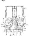
- Fig. 1 is a liquid-cooled cylinder head 1 for one multi-cylinder internal combustion engine, not shown, the left half being a first embodiment and the right half a second embodiment of the invention represents.
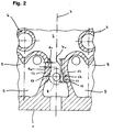
- the cylinder head 1 has a cooling water chamber 2 (see Fig. 2), of which only the inlet 2a is shown in FIG. 1. Of the Cooling water chamber 2 is down from a cylinder head floor 3 and up from one at a distance above the cylinder head floor 3 arranged cylinder head cover 4 limited. In the second embodiment the cylinder head 1 also has one in the inlet 2a arranged, free-standing projection 16 on. In the cooling water chamber 2 there are gas exchange channels 5 and in FIG. 2 shown chambers 6 arranged for spark plugs and / or injection nozzles, the gas exchange channels 5 according to FIG. 2 in the direction a transverse engine axis 7.
- cylinder head clamping screws only indicated in the figures 8 is the cylinder head 1 with the interposition of one here Not shown cylinder head gasket with a crankcase 9 of the internal combustion engine releasably connected.
- the pressing of the Cylinder head 1 to the crankcase 9 and thus the bracing the cylinder head gasket between cylinder head 1 and crankcase 9 takes place when the cylinder head screws 8 are tightened with the necessary screw preload.
- the cylinder head screws 8 extend part of their length free through a section, in this case the inlet 2a, the Cooling water chamber 2 in the cylinder head 1 and through a cooling water chamber section 10 in the crankcase 9.
- the cylinder head bolts 8 are flowed around by the cooling water and quickly on the Brought temperature of the surrounding components 1, 9.
- the cylinder head bolts 8 are by screw pipes described in more detail below 11 of the cylinder head 1 passed, which for Distribution of the bolt clamping forces of the cylinder head bolts 8 serve from the cylinder head cover 4 to the cylinder head base 3.
- Fig. 2 As can be seen from Fig. 2, according to the invention are in both Embodiments of the screw pipes 11 for the cylinder head screws 8 partly through adjacent wall sections 12 in particular, similar gas exchange channels 5, such as Inlet channels formed, the wall portions 12 in Area of the cylinder head screws 8 to form ribs 13 are thickened.
- This configuration according to the invention the screw pipes 11 distributes the screw clamping forces in areas 14 below the gas exchange channels 5 (see Fig. 1).
- Fig. 1 is the introduction of force by the cylinder head screw 8 in the cylinder head 1 and the subsequent distribution of forces over the ribs 13 into the areas 14 below the gas exchange channels 5 marked with dash-dotted arrows 15, the projection 16 in the second embodiment none Has an influence on this distribution of forces because of the lead 16 is not supported from below, but freely in the inlet 2a or the cooling water chamber section 10 protrudes.
- the preload the rib 13 is due to its special shape on the wall sections 12 of the gas exchange channels 5 in the direction of arrow 15 on the Aligned cylinder head gasket, which also in the the cylinder head bolts 8 adjacent areas 14 between the Gas exchange channels 5 a sufficient surface pressure on the Seal is achieved.
Landscapes
- Engineering & Computer Science (AREA)
- Chemical & Material Sciences (AREA)
- Combustion & Propulsion (AREA)
- Mechanical Engineering (AREA)
- General Engineering & Computer Science (AREA)
- Cylinder Crankcases Of Internal Combustion Engines (AREA)
Abstract
Description
- Fig. 1
- einen Teil eines Längsschnitts durch einen flüssigkeitsgekühlten Zylinderkopf einer mehrzylindrigen Brennkraftmaschine, der mit einem Kurbelgehäuse der Brennkraftmaschine verbunden ist, und
- Fig. 2
- einen Teil eines Schnittes durch den Zylinderkopf der Brennkraftmaschine gemäß Linie II-II aus Fig. 1.
- ARmin
- = erforderlicher Mindestquerschnitt der Rippe,
- dK
- = Dicke der Gaswechselkanalwand,
- dV
- = Dicke der einen Teil der Rippe bildenden Verdickung,
- bV
- = Breite der Verdickung,
- FS
- = Schraubenkraft der Zylinderkopfschraube und
- σSstreck
- = Streckgrenze der Zylinderkopfschraube.
Claims (2)
- Flüssigkeitsgekühlter Zylinderkopf für eine mehrzylindrige Brennkraftmaschine mit einem Kühlwasserraum, in dem in Richtung einer Motorquerachse verlaufende Gaswechselkanäle und mindestens eine Kammer für eine Zündkerze und/oder eine Einspritzdüse angeordnet sind, und mit Schraubenpfeifen zur Verteilung der Schraubenspannkräfte der Zylinderkopfschrauben, wobei der Zylinderkopf unter Zwischenschaltung einer Zylinderkopfdichtung mit einem Kurbelgehäuse der Brennkraftmaschine verbindbar ist,
dadurch gekennzeichnet,
daß benachbarte Wandabschnitte (12) der Gaswechselkanäle (5) im Bereich der Zylinderkopfschrauben (8) zur Bildung von Rippen (13) verdickt ausgeformt sind, die Teil der Schraubenpfeifen (11) sind. - Flüssigkeitsgekühlter Zylinderkopf für eine mehrzylindrige Brennkraftmaschine nach Anspruch 1,
dadurch gekennzeichnet,
daß die Zylinderkopfschrauben (8) über mindestens einen Teil ihrer Länge von Kühlwasser vollständig umgeben sind.
Applications Claiming Priority (2)
| Application Number | Priority Date | Filing Date | Title |
|---|---|---|---|
| DE19737492 | 1997-08-28 | ||
| DE19737492A DE19737492C1 (de) | 1997-08-28 | 1997-08-28 | Flüssigkeitsgekühlter Zylinderkopf einer mehrzylindrigen Brennkraftmaschine |
Publications (3)
| Publication Number | Publication Date |
|---|---|
| EP0899445A2 true EP0899445A2 (de) | 1999-03-03 |
| EP0899445A3 EP0899445A3 (de) | 2000-01-12 |
| EP0899445B1 EP0899445B1 (de) | 2003-02-26 |
Family
ID=7840435
Family Applications (1)
| Application Number | Title | Priority Date | Filing Date |
|---|---|---|---|
| EP98114792A Expired - Lifetime EP0899445B1 (de) | 1997-08-28 | 1998-08-06 | Flüssigkeitsgekühlter Zylinderkopf einer mehrzylindrigen Brennkraftmaschine |
Country Status (3)
| Country | Link |
|---|---|
| US (1) | US6129064A (de) |
| EP (1) | EP0899445B1 (de) |
| DE (1) | DE19737492C1 (de) |
Cited By (1)
| Publication number | Priority date | Publication date | Assignee | Title |
|---|---|---|---|---|
| DE102009041708A1 (de) * | 2009-09-16 | 2011-03-24 | GM Global Technology Operations, Inc., Detroit | Schraubenpfeife für einen Zylinderkopf einer Brennkraftmaschine, Zylinderkopf, Brennkraftmaschine und Fahrzeug sowie Verfahren zur Herstellung einer Schraubenpfeife |
Families Citing this family (1)
| Publication number | Priority date | Publication date | Assignee | Title |
|---|---|---|---|---|
| US8904975B2 (en) * | 2011-04-11 | 2014-12-09 | Toyota Jidosha Kabushiki Kaisha | Cylinder head of internal combustion engine |
Citations (2)
| Publication number | Priority date | Publication date | Assignee | Title |
|---|---|---|---|---|
| JPS5996341A (ja) | 1982-11-22 | 1984-06-02 | 株式会社 中井(保)組 | 土中への筒体設置方法 |
| DE3836117C1 (en) | 1988-10-22 | 1989-07-27 | Krupp Mak Maschinenbau Gmbh, 2300 Kiel, De | Cylinder head for internal combustion engines |
Family Cites Families (15)
| Publication number | Priority date | Publication date | Assignee | Title |
|---|---|---|---|---|
| DE1220202B (de) * | 1964-05-08 | 1966-06-30 | Daimler Benz Ag | Anordnung von Zylinderlaufbuchsen, insbesondere von nassen Zylinderlaufbuchsen bei Brennkraftmaschinen |
| DE1301655C2 (de) * | 1965-01-12 | 1970-04-23 | Daimler Benz Ag | Brennkraftmaschine mit fluessigkeitsgekuehlten Zylinderlaufbuchsen |
| DE2143734B2 (de) * | 1971-09-01 | 1973-10-04 | Daimler-Benz Ag, 7000 Stuttgart | Brennkraftmaschine mit einem in den Durchgang fur das Kuhlwasser zwischen Zylinderkopf und Kurbeigehause einge setzten Zwischenrohr |
| DE3228922A1 (de) * | 1982-08-03 | 1984-02-09 | M.A.N. Maschinenfabrik Augsburg-Nürnberg AG, 8500 Nürnberg | Verbindung von vorzugsweise dynamisch hochbeanspruchten maschinenteilen durch mehrere lange schrauben und mehrere kurze schrauben |
| JPS5996341U (ja) * | 1982-12-20 | 1984-06-29 | マツダ株式会社 | エンジンのシリンダヘツド構造 |
| DE3513126C2 (de) * | 1985-04-12 | 1987-02-12 | Daimler-Benz Ag, 7000 Stuttgart | Flüssigkeitsgekühlter Vierventil-Zylinderkopf für eine mehrzylindrige Brennkraftmaschine |
| DE3545333A1 (de) * | 1985-12-20 | 1987-07-02 | Kloeckner Humboldt Deutz Ag | Zylinderkopf |
| DE3616629A1 (de) * | 1986-05-16 | 1987-11-19 | Audi Ag | Brennkraftmaschine |
| DE3726027A1 (de) * | 1987-08-05 | 1989-02-16 | Alcan Gmbh | Waermebeaufschlagtes bauteil |
| DE3922885A1 (de) * | 1989-07-12 | 1991-01-17 | Man Nutzfahrzeuge Ag | Zylinderkopfdichtung fuer hubkolbenmaschinen, insbesondere brennkraftmaschinen |
| DE4223780C2 (de) * | 1992-07-18 | 1996-04-11 | Bayerische Motoren Werke Ag | Schraubverbindung für einen Zylinderkopf einer Brennkraftmaschine |
| IT1270244B (it) * | 1993-07-23 | 1997-04-29 | Porsche Ag | Accoppiamento a viti della testa cilindri di un motore a combustione interna |
| US5630389A (en) * | 1995-09-29 | 1997-05-20 | Self; Kevin G. | Cylinder head bolt plug |
| SE9503622L (sv) * | 1995-10-13 | 1996-09-23 | Scania Cv Ab | Anordning för avtätning av en förbränningsmotors förbränningsrum |
| DE19644530C1 (de) * | 1996-10-26 | 1998-02-12 | Daimler Benz Ag | Zylinderkopf für eine Mehrzylinder-Brennkraftmaschine |
-
1997
- 1997-08-28 DE DE19737492A patent/DE19737492C1/de not_active Expired - Fee Related
-
1998
- 1998-08-06 EP EP98114792A patent/EP0899445B1/de not_active Expired - Lifetime
- 1998-08-28 US US09/143,626 patent/US6129064A/en not_active Expired - Fee Related
Patent Citations (2)
| Publication number | Priority date | Publication date | Assignee | Title |
|---|---|---|---|---|
| JPS5996341A (ja) | 1982-11-22 | 1984-06-02 | 株式会社 中井(保)組 | 土中への筒体設置方法 |
| DE3836117C1 (en) | 1988-10-22 | 1989-07-27 | Krupp Mak Maschinenbau Gmbh, 2300 Kiel, De | Cylinder head for internal combustion engines |
Cited By (1)
| Publication number | Priority date | Publication date | Assignee | Title |
|---|---|---|---|---|
| DE102009041708A1 (de) * | 2009-09-16 | 2011-03-24 | GM Global Technology Operations, Inc., Detroit | Schraubenpfeife für einen Zylinderkopf einer Brennkraftmaschine, Zylinderkopf, Brennkraftmaschine und Fahrzeug sowie Verfahren zur Herstellung einer Schraubenpfeife |
Also Published As
| Publication number | Publication date |
|---|---|
| EP0899445A3 (de) | 2000-01-12 |
| DE19737492C1 (de) | 1998-10-29 |
| US6129064A (en) | 2000-10-10 |
| EP0899445B1 (de) | 2003-02-26 |
Similar Documents
| Publication | Publication Date | Title |
|---|---|---|
| DE2420051C3 (de) | FifissigkeitsgekUhlter Zylinderkopf für mehrzylindrige Brennkraftmaschinen | |
| EP0928405B1 (de) | Plattenwärmetauscher, insbesondere öl/kühlmittel-kühler für kraftfahrzeuge | |
| DE10258319A1 (de) | Flachdichtung, insbesondere Abgaskrümmerdichtung, sowie eine solche Dichtung aufnehmende Baugruppe | |
| DE2429355A1 (de) | Verbrennungskraftmaschine | |
| DE2638025B2 (de) | Wassergekühlte Brennkraftmaschine | |
| DE2742296A1 (de) | Einrichtung zur verbindung eines einteiligen auspuffsammelrohres mit den zylinderkoepfen mehrzylindriger, reihenfoermiger verbrennungsmotoren | |
| AT402325B (de) | Zylinderkopf einer flüssigkeitsgekühlten brennkraftmaschine mit in reihe angeordneten zylindern | |
| EP1144836B1 (de) | Brennkammer-kühlstruktur für ein raketentriebwerk | |
| EP0845592B1 (de) | Kühlelement und Einspritzdüse mit Kühlelement für eine Hubkolbenbrennkraftmaschine | |
| EP1769207B1 (de) | Platten-wärmetauscher | |
| DE19644530C1 (de) | Zylinderkopf für eine Mehrzylinder-Brennkraftmaschine | |
| DE102004062522B4 (de) | Zylinderkopf mit Versteifung | |
| EP0899445B1 (de) | Flüssigkeitsgekühlter Zylinderkopf einer mehrzylindrigen Brennkraftmaschine | |
| DE69509411T2 (de) | Zylinderblock für eine brennkraftmaschine | |
| WO2003100237A1 (de) | Zylinderkopf einer brennkraftmaschine | |
| EP1972772B1 (de) | Zylinderkopf für eine flüssigkeitsgekühlte Brennkraftmaschine | |
| DE19600448C1 (de) | Flüssigkeitsgekühlter Zylinderkopf für eine Brennkraftmaschine | |
| DE19508986C1 (de) | Zylinderkopf für eine Brennkraftmaschine | |
| DE19637122C1 (de) | Flüssigkeitsgekühlter Zylinderkopf | |
| DE4344356A1 (de) | Zylinderkopf für eine Brennkraftmaschine mit Sekundärluftzufuhr | |
| DE9401035U1 (de) | Kühleinrichtung für ein Kraftfahrzeug | |
| DE2952490C2 (de) | Zylinderkopf für kompressionsgezündete Brennkraftmaschinen mit Vorbrennkammern | |
| DE19640122C1 (de) | Zylinderkopf-Kühlungsvorrichtung | |
| AT519245B1 (de) | Flüssigkeitsgekühlte Brennkraftmaschine mit Hülsenelement | |
| EP1669582B1 (de) | Integriertes Einspritzsystem |
Legal Events
| Date | Code | Title | Description |
|---|---|---|---|
| PUAI | Public reference made under article 153(3) epc to a published international application that has entered the european phase |
Free format text: ORIGINAL CODE: 0009012 |
|
| AK | Designated contracting states |
Kind code of ref document: A2 Designated state(s): DE FR GB IT Kind code of ref document: A2 Designated state(s): FR GB IT |
|
| AX | Request for extension of the european patent |
Free format text: AL;LT;LV;MK;RO;SI |
|
| RAP1 | Party data changed (applicant data changed or rights of an application transferred) |
Owner name: DAIMLERCHRYSLER AG |
|
| PUAL | Search report despatched |
Free format text: ORIGINAL CODE: 0009013 |
|
| AK | Designated contracting states |
Kind code of ref document: A3 Designated state(s): AT BE CH CY DE DK ES FI FR GB GR IE IT LI LU MC NL PT SE |
|
| AX | Request for extension of the european patent |
Free format text: AL;LT;LV;MK;RO;SI |
|
| 17P | Request for examination filed |
Effective date: 19991209 |
|
| AKX | Designation fees paid |
Free format text: DE FR GB IT |
|
| GRAG | Despatch of communication of intention to grant |
Free format text: ORIGINAL CODE: EPIDOS AGRA |
|
| 17Q | First examination report despatched |
Effective date: 20020625 |
|
| GRAG | Despatch of communication of intention to grant |
Free format text: ORIGINAL CODE: EPIDOS AGRA |
|
| GRAH | Despatch of communication of intention to grant a patent |
Free format text: ORIGINAL CODE: EPIDOS IGRA |
|
| GRAH | Despatch of communication of intention to grant a patent |
Free format text: ORIGINAL CODE: EPIDOS IGRA |
|
| RBV | Designated contracting states (corrected) |
Designated state(s): FR GB IT |
|
| GRAA | (expected) grant |
Free format text: ORIGINAL CODE: 0009210 |
|
| REG | Reference to a national code |
Ref country code: DE Ref legal event code: 8566 |
|
| AK | Designated contracting states |
Designated state(s): FR GB IT |
|
| REG | Reference to a national code |
Ref country code: GB Ref legal event code: FG4D Free format text: NOT ENGLISH |
|
| GBT | Gb: translation of ep patent filed (gb section 77(6)(a)/1977) |
Effective date: 20030509 |
|
| ET | Fr: translation filed | ||
| PLBE | No opposition filed within time limit |
Free format text: ORIGINAL CODE: 0009261 |
|
| STAA | Information on the status of an ep patent application or granted ep patent |
Free format text: STATUS: NO OPPOSITION FILED WITHIN TIME LIMIT |
|
| 26N | No opposition filed |
Effective date: 20031127 |
|
| PGFP | Annual fee paid to national office [announced via postgrant information from national office to epo] |
Ref country code: GB Payment date: 20050725 Year of fee payment: 8 |
|
| PGFP | Annual fee paid to national office [announced via postgrant information from national office to epo] |
Ref country code: FR Payment date: 20050812 Year of fee payment: 8 |
|
| PGFP | Annual fee paid to national office [announced via postgrant information from national office to epo] |
Ref country code: IT Payment date: 20060831 Year of fee payment: 9 |
|
| GBPC | Gb: european patent ceased through non-payment of renewal fee |
Effective date: 20060806 |
|
| REG | Reference to a national code |
Ref country code: FR Ref legal event code: ST Effective date: 20070430 |
|
| PG25 | Lapsed in a contracting state [announced via postgrant information from national office to epo] |
Ref country code: GB Free format text: LAPSE BECAUSE OF NON-PAYMENT OF DUE FEES Effective date: 20060806 |
|
| PG25 | Lapsed in a contracting state [announced via postgrant information from national office to epo] |
Ref country code: FR Free format text: LAPSE BECAUSE OF NON-PAYMENT OF DUE FEES Effective date: 20060831 |
|
| PG25 | Lapsed in a contracting state [announced via postgrant information from national office to epo] |
Ref country code: IT Free format text: LAPSE BECAUSE OF NON-PAYMENT OF DUE FEES Effective date: 20070806 |