EP0898685B1 - Abat-jour et son procede de fabrication - Google Patents
Abat-jour et son procede de fabrication Download PDFInfo
- Publication number
- EP0898685B1 EP0898685B1 EP97920928A EP97920928A EP0898685B1 EP 0898685 B1 EP0898685 B1 EP 0898685B1 EP 97920928 A EP97920928 A EP 97920928A EP 97920928 A EP97920928 A EP 97920928A EP 0898685 B1 EP0898685 B1 EP 0898685B1
- Authority
- EP
- European Patent Office
- Prior art keywords
- ligature
- wall
- support ring
- apertures
- side wall
- Prior art date
- Legal status (The legal status is an assumption and is not a legal conclusion. Google has not performed a legal analysis and makes no representation as to the accuracy of the status listed.)
- Expired - Lifetime
Links
- 238000000034 method Methods 0.000 title claims description 31
- 230000000694 effects Effects 0.000 claims description 2
- 238000004804 winding Methods 0.000 claims description 2
- 239000000463 material Substances 0.000 description 13
- 239000004033 plastic Substances 0.000 description 10
- 229920003023 plastic Polymers 0.000 description 10
- 238000004519 manufacturing process Methods 0.000 description 7
- PPBRXRYQALVLMV-UHFFFAOYSA-N Styrene Chemical compound C=CC1=CC=CC=C1 PPBRXRYQALVLMV-UHFFFAOYSA-N 0.000 description 6
- 238000010276 construction Methods 0.000 description 6
- 239000000853 adhesive Substances 0.000 description 5
- 230000001070 adhesive effect Effects 0.000 description 5
- 239000010985 leather Substances 0.000 description 4
- 230000003014 reinforcing effect Effects 0.000 description 4
- -1 for example Substances 0.000 description 2
- 238000002347 injection Methods 0.000 description 2
- 239000007924 injection Substances 0.000 description 2
- 239000002184 metal Substances 0.000 description 2
- 239000011087 paperboard Substances 0.000 description 2
- 239000004744 fabric Substances 0.000 description 1
- 210000003811 finger Anatomy 0.000 description 1
- 230000005484 gravity Effects 0.000 description 1
- 239000002991 molded plastic Substances 0.000 description 1
- 239000000123 paper Substances 0.000 description 1
- 239000004753 textile Substances 0.000 description 1
- 210000003813 thumb Anatomy 0.000 description 1
- 239000002023 wood Substances 0.000 description 1
Images


Classifications
-
- F—MECHANICAL ENGINEERING; LIGHTING; HEATING; WEAPONS; BLASTING
- F21—LIGHTING
- F21V—FUNCTIONAL FEATURES OR DETAILS OF LIGHTING DEVICES OR SYSTEMS THEREOF; STRUCTURAL COMBINATIONS OF LIGHTING DEVICES WITH OTHER ARTICLES, NOT OTHERWISE PROVIDED FOR
- F21V1/00—Shades for light sources, i.e. lampshades for table, floor, wall or ceiling lamps
- F21V1/26—Manufacturing shades
-
- Y—GENERAL TAGGING OF NEW TECHNOLOGICAL DEVELOPMENTS; GENERAL TAGGING OF CROSS-SECTIONAL TECHNOLOGIES SPANNING OVER SEVERAL SECTIONS OF THE IPC; TECHNICAL SUBJECTS COVERED BY FORMER USPC CROSS-REFERENCE ART COLLECTIONS [XRACs] AND DIGESTS
- Y10—TECHNICAL SUBJECTS COVERED BY FORMER USPC
- Y10S—TECHNICAL SUBJECTS COVERED BY FORMER USPC CROSS-REFERENCE ART COLLECTIONS [XRACs] AND DIGESTS
- Y10S493/00—Manufacturing container or tube from paper; or other manufacturing from a sheet or web
- Y10S493/95—Lamp shade
Definitions
- the present invention relates to a lampshade, and to a method for making the lampshade.
- Lampshades are provided in many shapes and forms, and are provided for use in connection with table lamps, standard lamps, ceiling suspended lights and the like.
- such lampshades comprise an upper support ring and a lower support ring, and a side wall or side walls extend between the upper and lower rings.
- the side wall may be an endless wall which extends completely around and between the two rings, or it may be formed in segments which extend between the two rings and are spaced apart circumferentially around the two support rings.
- the side wall or walls are secured to the upper and lower rings, and may be secured by adhesive, stitching or, indeed, by folding around the upper and lower support rings.
- Such forms of construction of lampshade will be well known to those skilled in the art.
- lampshade comprises an upper and a lower support ring and a single endless side wall or a plurality of side walls extending between the support rings, and the side wall or side walls is secured to one or both support rings by a ligature, which may be of leather, textile, such as, for example, a ribbon, coarse twine, wire or the like, or cord.
- the side wall or walls are provided with a row of spaced apart apertures adjacent one or both the top and bottom edges of the side wall or side walls and the ligature is threaded sequentially through the apertures and wound around the adjacent support ring in a helical form.
- a lampshade of this type is disclosed in U.S. Patent Specification No. 2,435,759 of Spaw.
- European Patent Specification No. 325878 discloses a lampshade with a removable cover in which the removable cover is a skirt. The skirt is held in place with a combination of flaps, strips, and annular metal components.
- the patent specification does not disclose or suggest a method which obviates the need for time-consuming threading procedures in the mass production of lampshades having a ligature component in its assembly.
- An object of the invention is to provide an improved simplified method for making a lampshade.
- a further object of the invention is to provide an improved lampshade having a simplified construction.
- Yet a further object of the invention is to provide an improved method of manufacturing a lampshade which obviates the need for threading of a ligature but results in a lampshade having a component resembling a threaded ligature.
- a method for making a lampshade of the type which comprises at least one support ring, and a side wall secured to the support ring by a ligature, the side wall having a plurality of spaced apart apertures formed therethrough for receiving the ligature, wherein the at least one support ring comprises a plurality of ligature receiving means at spaced apart locations along the support ring, and the method comprises the steps of:
- a first access means is provided to each wall aperture, the respective first access means extending from a side edge of the wall adjacent the wall apertures to the corresponding wall aperture for accommodating the corresponding portion of the ligature into the corresponding wall apertures.
- a second access means is provided in the support ring to each ligature receiving means for accommodating respective portions of the ligature to the corresponding ligature receiving means.
- each ligature receiving means is formed by an aperture extending through the support ring.
- the respective wall and ring apertures and their corresponding first and second access means are aligned for receiving the said portions of the ligature, and preferably, the said portions of the ligature are passed sequentially through the respective first and second access means to the wall and ring apertures, simultaneously.
- the ligature is pulled taut.
- the ligature is pulled taut at the outer side of the side wall and the support ring assembly from an inner side of the side wall to the outer side thereof.
- the ligature is inserted through respective adjacent wall and ring apertures to give the effect of a helically wound ligature around the ring and a portion of the side wall intermediate the wall apertures and the adjacent side edge of the side wall.
- the first and second access means are provided by first and second access slits or slots, respectively, and advantageously, the first and second access slots are inclined to the side edge of the side wall adjacent the wall apertures, and when viewed from the outer side of the side wall the first access slots define a part of each wind of the helix formed by the ligature so that the first access slots are concealed by corresponding adjacent portions of the ligature which extends from the respective wall apertures to the adjacent side edge and which coincide with the respective first access slots.
- the portion of the ligature adjacent the outer side of the side wall adjacent the side edge is held adjacent the first access slot for preventing the ligature being pulled through the first access slot a second time.
- the ligature is pulled taut each time a portion of the ligature is inserted through one of the wall and ring apertures for tightening a portion of the ligature extending between that wall and ring aperture and the next adjacent wall and ring aperture through which the ligature had previously been inserted.
- each ligature receiving means comprises a grip means which is located in the support ring, and preferably, each grip means is located in a corresponding one of the second apertures in the support ring.
- the respective portions of the ligature are inserted through the respective corresponding wall apertures for engaging the grip means.
- the grip means comprises resiliently deformable slits deformable inwards when one of the portions of the ligature is urged against the slits.
- the respective wall and ring apertures are aligned for receiving the said ligature.
- a first end of the ligature is first secured in an aligned pair of wall and ring apertures and the ligature is doubled adjacent the subsequent wall and ring apertures and inserted through the wall aperture and the grip means.
- the invention provides a lampshade comprising a side wall and at least one, and preferably two support rings, the support rings being spaced apart, and being located adjacent a top and bottom edge of the side wall, the side wall being secured to each support ring by a ligature of which a plurality of portions are inserted into respective spaced apart apertures formed in the side wall adjacent the support ring, the said portions of the ligature securing the side wall to the support ring by engaging respective spaced apart ligature receiving means on the support ring, the respective corresponding wall apertures and ligature receiving means being aligned for receiving the ligature.
- each ligature receiving means comprises a grip means for receiving and securing the ligature in the support ring.
- each grip means is located in a corresponding aperture which extends through the support ring.
- the grip means is a non-return type grip means.
- a portion of the ligature extending between one wall aperture and its next adjacent wall aperture is pulled taut as the ligature is being inserted into the said next adjacent wall aperture and corresponding ligature receiving means.
- a first access means is provided to each wall aperture, each first access means extending from an adjacent side edge of the side wall to the corresponding wall aperture for accommodating the ligature into the wall aperture, and preferably, a second access means is provided in the support ring for each ligature receiving means, each second access means extending from a side edge of the support ring which corresponds with a side edge of the side wall to the corresponding receiving means for accommodating the ligature into the ligature receiving means.
- the first and second access means comprises a first and second access slit or slot, respectively.
- the respective first and second access slots are inclined relative to the adjacent side edges of the side wall, and define part of one wind of a helix.
- the ligature is engaged in the wall aperture and the ligature receiving means to appear as though it were wound in the form of a helix around the support ring and a portion of the side wall between the wall apertures and the adjacent side edge of the side wall.
- portions of the ligature extending from wall aperture to the adjacent side edge of the side wall lie along and conceal the corresponding first access slot.
- the wall apertures are located adjacent the side edge of the side wall which is adjacent to the corresponding support ring.
- the ligature comprises an elongate strip of leather. In an alternative embodiment of the invention the ligature comprises an elongate cord.
- a method for the manufacture of a lampshade in which the ligature is secured to one or more of the ligature receiving means on the ring at least every second time a portion of the ligature is passed through an aperture and the ligature is tightened onto the ligature receiving means.
- the ligature is secured to one of the ligature receiving means each time a portion of the ligature is passed through the aperture and more preferably, the portions of the ligature are passed through the apertures to form a loop each loop being secured to a ligature receiving means.
- the apertures are located adjacent an edge of the side wall, and an access means is provided to each aperture from the adjacent edge and the ligature is entered into each aperture through the access means.
- each ligature receiving means comprises a hook extending from the ring.
- the hook extends between the ring towards a centre of the ring.
- a groove is formed in the ring adjacent each hook for accommodating the ligature from the corresponding aperture in the side wall to the hook.
- a top ring and a bottom ring is provided, the top and bottom rings being spaced apart and the side wall extending between the respective rings, and the side wall extends completely around the ring.
- the side wall is endless.
- the invention also provides a lampshade comprising a side wall having a top and a bottom edge, and at least one support ring, the at least one support ring being located adjacent at least one of the top and bottom edges of the side wall, the side wall being secured to the at least one support ring by a ligature through a plurality of spaced apart apertures formed in the side wall adjacent the support ring, wherein a plurality of spaced apart ligature receiving means are provided on the at least one support ring aligned with the respective corresponding wall apertures, and a plurality of portions of the ligature are inserted sequentially through the respective wall apertures and are engaged on the respective spaced apart ligature receiving means on the support ring for securing the side wall to the at least one support ring, such that the ligature need not be threaded through each aperture and wound around the support ring.
- the ligature is passed over at least one ligature receiving means at least every second time the ligature passes through each wall aperture without the need for
- the ligature engages one of the ligature receiving means each time it passes through an aperture.
- the ligature is in the form of a plurality of loops passed through corresponding apertures and engaged on corresponding ligature receiving means and the apertures are located adjacent an edge of the side wall.
- an access means is provided to each aperture from the edge, and the access means comprises a slit extending from a corresponding aperture to the edge of the side wall.
- the ligature receiving means comprises a hook, and the hook extends from the ring towards a centre defined by the ring.
- a pair of rings are provided, namely, the top ring and the bottom ring which are spaced apart from each other, and the side wall extends between the top and bottom ring.
- the side wall extends completely around the rings, and advantageously, the side wall is of frusto conical shape.
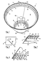
- the lampshade 1 as well as being in accordance with the invention is also made by a method according to the invention which will be described below.
- the lampshade 1 is provided with a mounting frame 53 for mounting the lampshade on a lamp or other light fitting.
- the mounting frame 53 is shown in broken lines for clarity.
- the mounting frame 53 can be of a variety of types and can be integral with the lampshade 1 or attachable to the lampshade 1.
- the mounting frame 53 has been omitted from Figs. 2 to 17 for clarity.
- the lampshade 1 comprises a pair of support rings, namely, a top support ring 3 and a bottom support ring 4, both of plastics material.
- a side wall 5 of a flexible resilient plastics material extends between and completely around the support rings 3 and 4, and overlaps the rings 3 and 4.
- the side wall 5 is secured to the top and bottom reinforcing rings 3 and 4 by respective ligatures 7, which are not illustrated in Fig. 1.
- the ligatures 7 are typically of cord and are in the form of a helix.
- the top and bottom support rings 3 and 4 comprise an annular reinforcing section 8 and a relatively thin annular portion 9 extending from the reinforcing section 8.
- the portions 9 of the respective rings 3 and 4 terminate in side edges 10, which when the side wall 5 is secured to the rings 3 and 4 coincide with corresponding top and bottom edges 11 and 12, respectively, of the side wall 5.
- the thin portion 9 of the bottom support ring 4 diverges outwardly and takes up the approximate angle of divergence of the side wall 5, while the thin portion 9 of the top support ring converges inwardly to take up the approximate angle of convergence of the side wall 5 adjacent the top ring 3.
- Two rows of spaced apart apertures 15 are provided in the side wall 5 adjacent but spaced apart in from the top and bottom side edges 11 and 12 for receiving the ligatures 7.
- a plurality of spaced apart ligature receiving means, each of which is provided by an aperture 16 are located in the thin portions 9 of the respective top and bottom support rings 3 and 4, also for receiving the ligatures 7.
- the ring apertures 16 are alignable with the corresponding wall apertures 15.
- a plurality of first and second access means are provided in the side wall 5 and the thin portions 9 of the support rings 3 and 4.
- the first access means are provided by first access slits or slots 18 which extend from the top and bottom side edges 11 and 12 of the side wall 5 to the wall apertures 15.
- the second access means are provided by respective second access slits or slots 20 which extend from the side edges 10 of the support rings 3 and 4 to the ring apertures 16.
- the first access slots 18 and the second access slots 20 are also alignable with each other.
- the first and second access slots 18 and 20 are inclined to the respective top and bottom edges 10, 11 and 12, and define part of the helix formed by the respective ligatures 7, so that portions 21 of the ligatures 7 which extend between respective ones of the wall apertures 15 and the top or bottom edge 11 or 12 of the side wall extend over the corresponding first access slots 18 for concealing the access slots 18.
- the dimensions of the first and second access slots 18 and 20, and the diameter of the ligatures 7 are so chosen that once assembled there is no danger of the ligatures 7 passing back into any of the access slots 18 and 20, which would thus cause disengagement of one of the ligatures 7 from the corresponding ring and wall apertures 15 and 16.
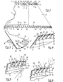
- the lampshade 1 is made according to the method of the invention which is as follows. Initially, the side wall 5 and top and bottom support rings 3 and 4 are held together, typically, by a few dots of a suitable adhesive located at spaced apart intervals around the support rings 3 and 4 between the respective rings 3 and 4 and the side wall 5.
- a first loop of the ligature 7 is formed as illustrated in Figs. 5 and 6 by the reference a .
- the first loop a is passed through one of the wall and ring apertures 15 and 16.
- the ligature 7 is then inserted into the next adjacent wall and ring apertures 15 and 16 by urging a portion of the ligature 7 through the corresponding first and second access slots 18 and 20 into the said next adjacent wall and ring apertures 15 and 16.
- the first two loops b of the helix formed by the ligature 7 are illustrated having been formed, and the next loop of the helix is being formed.
- the ligature 7 is then urged into the first and second access slots 18 and 20 of the next wall and ring apertures 15 and 16 which are indicated by the reference letter c in Figs. 5 and 6. While the portion of the ligature 7 which is being urged through the access slots 18 and 20 into the apertures c a portion of the ligature which forms the loop of the helix which is being formed is held by the thumb or a finger at d which is adjacent the edge 11 or 12 of the side wall 5, and also adjacent the entry of the previous access slots 18 and 20.
- a portion of the ligature 7 is arranged to extend along and to conceal the previous first access slot 18.
- the ligature 7 is then pulled tightly to form the loop of the helix.
- excess tension is not applied to the ligature 7 in order to avoid any danger of the ligature 7 re-entering the previous first and second access slots 18 and 20 at the point d .
- the ligature 7 is illustrated in Fig. 6 having been entered in the wall and ring apertures c and being pulled taut to form the loop of the helix.
- a lampshade 30 according to a second embodiment of the invention.
- the lampshade 30 is substantially similar to the lampshade 1, and similar components are identified by the same reference numerals.
- the main difference between the lampshade 30 and the lampshade 1 is in the respective top and bottom support rings 3 and 4 and the fact that first and second access slots 18 and 19 to the wall and ring apertures 15 and 16 are not required.
- the ligatures 7 instead of the ligatures 7 being wound in the form of a helix, the ligatures 7 are secured to the side wall 5 and top and bottom support rings 3 and 4 in the form of stitching.
- the top and bottom support rings 3 and 4 comprise a reinforcing section 31 from which a relatively thin portion 32 extends.
- the ring apertures 16 are formed in the thin portion 32.
- Ligature receiving means in this embodiment of the invention are provided by a plurality of sets of spaced apart slits 38 formed in a strip 35 of resilient flexible material which radiate outwardly from a central point 39. The strip 35 is bonded to the thin portion 32 of the respective support rings 3 and 4 with the sets of slits 38 aligned with the corresponding ring apertures 16.
- Each set of slits 38 defines resiliently deformable portions 40 which deform inwardly on one of the portions of the ligature 7 being urged in through the ring apertures 16, and then retain that portion of the ligature 7 in secure engagement therewith thereby preventing withdrawal of the portion of the ligatures 7.
- the lampshade 30 is made according to the method of the invention as follows. Initially, the side wall 5 is secured to the top and bottom rings 3 and 4 with corresponding wall and ring apertures 15 and 16 aligned. Typically, the side wall 5 is secured to the top and bottom rings 3 and 4 by a few dots of adhesive between the side wall 5 and the respective rings 3 and 4 as already described. The ligatures 7 are then secured to the top and bottom of the lampshade 30.
- the side wall 5 is first formed and pre-moulded top and bottom rings 3 and 4 simply placed in the inverted lampshade 30.
- injection moulded rings 3 and 4 are used.
- Injection moulded plastics rings 3 and 4 have the advantage that the dimensions of same can be accurately reproduced in manufacture. Accordingly, the rings 3 and 4 can be dimensioned to be automatically correctly positioned in an inverted lampshade under the force of gravity adjacent the edges of the lampshade 30 without requiring the use of adhesive to locate the rings 3 and 4.
- One end of the ligature is secured in any one of a corresponding pair of the wall and ring apertures 15 and 16 which is selected, and the ligature is then lightly stretched is doubled adjacent the next wall and ring apertures 15 and 16 and inserted through the wall aperture 15, and in turn the ring aperture 16 and secured in the slits 38.
- This method is continued until the ligature 7 is secured through the side wall 5 to the top or bottom support ring 3 or 4 to form a row of stitching as illustrated in Fig. 10.
- the second ligature 7 is then secured in similar fashion through the side wall 5 to the other of the top and bottom support ring 3 and 4.
- FIGs 14 to 17 show a third embodiment of a lampshade 1 in accordance with the invention which is made by a method also according to the invention which will be described in detail below.
- the lampshade 1 is broadly similar to those shown in Figures 1 to 13 in that it comprises a side wall 5 of semi-rigid material, which in this case is a plastics material, and which is of frusto conical shape.
- the side wall 5 is secured to an upper ring 3 and a lower ring 4 by respective ligatures 7 which in this case are provided by elongate strips of leather.
- the side wall 5 is formed from a single sheet of plastics material which is cut to shape and secured along a seam 41 by adhesive to form what is effectively an endless side wall 5.
- a plurality of spaced apart apertures 15 are arranged in two rows in the sidewall 5, namely, an upper row 42 and a lower row 43 for accommodating the respective ligatures 7 to the upper and lower rings 3 and 4, respectively.
- the rows 42 and 43 of apertures 15 are located relatively closely to upper and lower edges 11 and 12, respectively, of the side wall 5.
- An access means, namely, a slit 18 extends from each aperture 15 to the adjacent edge 11 or 12 for accommodating quick entry of the ligature 7 into the corresponding apertures 15.
- the upper and lower rings 3 and 4 are of plastics material, and are similar to each other with the exception that the upper ring 3 is of smaller diameter than the lower ring 4 for accommodating the frusto conical shape of the side wall 5.
- a plurality of ligature receiving means namely, hooks 44 for engaging the ligature 7 extend from the rings 3 and 4, in a direction generally inwardly towards a centre 45 defined by the respective rings 3 and 4.
- One aperture 15 is provided in the respective upper and lower rows 42 and 43 of apertures 15 for each hook 44.
- Grooves 46 extend radially through the rings 3 and 4 adjacent the hooks 44 for accommodating loops 47 of the ligature 7 from the apertures 15 to corresponding hooks 44.
- recesses 48 are formed in portions 49 of the respective rings 3 and 4 between the hooks 44.
- a wall 50 of one of the portions 49 is provided with four slots 51 for engaging and securing the two ends 52 of the ligature 7.
- the side wall 5 is initially secured to the lower ring 4, and is then secured to the upper ring 3. With the side wall 5 formed into the frusto conical shape the lower ring 4 is engaged within the side wall 5 adjacent its lower edge 12. During this operation, and during the securing of the side wall 2 to the lower ring 4 the side wall 5 is inverted so that the lower edge 12 is facing upwards.
- the apertures 15 are aligned with the grooves 46 in the lower ring 4.
- One end 52 of the ligature 7 is secured in one of the slots 51 in the lower ring 4.
- the ligature 7 is then hooked onto the adjacent hook 44 and is passed through the corresponding groove 46, and is passed through and is entered in the adjacent aperture 15 of the side wall 5 by entering the ligature 7 through the corresponding slit 18.
- a loop 47 is then formed in the ligature 7, and the loop 47 is entered into the next adjacent aperture 15 through the slit 18, and the loop 47 is in turn looped onto the corresponding hooks 44, and a free portion of the ligature 7 is pulled until the loop 47 tightly engages the hook 44, thereby retaining the adjacent portion of the side wall 5 to the lower ring 4.
- Another loop 47 is formed and entered into the aperture 15 and is looped onto the corresponding hook 44, and a further free portion of the ligature 7 is pulled tightly thereby tightening the ligature 7 onto the hook 47 for further securing the side wall 5 onto the lower ring 4.
- This operation continues until loops 47 have been entered into all the apertures 15 and looped onto the corresponding hooks 44.
- the other free end 52 of the ligature 7 is then engaged in one of the other slots 51 so that both free ends 52 of the ligature 7 are secured in the slots 52.
- the side wall 5 On the side wall 5 having been secured to the lower ring 4, the side wall 5 is then secured to the upper ring 3.
- the side wall 5 is reinverted so that the upper edge 11 faces upwardly.
- the ligature could be secured in the following fashion. After securing one end 52 to the lower ring 4 and hooking the ligature 7 onto the adjacent hook 44, and in turn entering the ligature into the corresponding aperture 15, the ligature 7 without forming a loop 47 could then be entered into the next aperture 15 through the corresponding slit 18, and then could be looped around the hook 44 and passed back out through the groove 46 and that aperture 15 before being entered into the next adjacent aperture 15 through the corresponding slit 18, and so on.
- the lampshade 1 has been described as comprising a side wall 5 which is effectively endless, it is envisaged that the lampshade may be of the type comprising an upper ring and a lower ring with one or a plurality of side walls extending between the upper and lower rings.
- the side walls may be located adjacent each other, or may be spaced apart.
- the side wall has been described as being of a plastics material
- the side wall may be of any other material, for example, paperboard, plastics, styrene, fabric or paper, which may be laminated to paperboard, plastics or styrene, or any other suitable material.
- the side wall may be rigid, semi-rigid or indeed, flexible.
- upper and lower rings of other shape and construction may be provided.
- the upper and lower rings may be of any suitable material, for example, wood, metal, plastics, styrene, wire, or the like.
- the lampshade may comprise only one ring, for example, a lower ring, and in other cases, it is envisaged that the upper and lower rings 3 and 4 may be joined by connecting members.
- a closure ring may be provided for closing the recess in the upper and lower rings.
- Ligature receiving means other than hooks 44 may also be provided. Where the receiving means are provided by hooks 44, the hooks 44 may extend in any desired direction from the rings 3 and 4.
- each loop would be threaded through a corresponding aperture.
- the ligature has been described as being of leather, the ligature may be of any other suitable material.
Landscapes
- Engineering & Computer Science (AREA)
- Manufacturing & Machinery (AREA)
- General Engineering & Computer Science (AREA)
- Prostheses (AREA)
- Non-Portable Lighting Devices Or Systems Thereof (AREA)
- Dental Tools And Instruments Or Auxiliary Dental Instruments (AREA)
Claims (24)
- Procédé de fabrication d'un abat-jour du type qui comprend au moins un anneau de support (3, 4) et une paroi latérale (5) fixée à l'anneau de support (3, 4) par une ligature (7), la paroi latérale (5) ayant une pluralité d'ouvertures (15) mutuellement espacées formées à travers celle-ci pour recevoir la ligature (7), caractérisé en ce que cet au moins un anneau de support (3, 4) comprend une pluralité de moyens de réception de ligature (16, 40, 44) en des emplacements mutuellement espacés le long de l'anneau de support (3, 4), et le procédé comprenant les étapes suivantes :insertion séquentielle de parties respectives de la ligature (7) de façon dans les ouvertures de paroi (15), etfixation des parties respectives de la ligature (7) aux moyens de réception de ligature (16, 40, 44) sur l'anneau de support (3, 4) correspondant, de telle façon qu'il ne soit pas nécessaire d'enfiler la ligature à travers chaque ouverture et de l'enrouler autour de l'anneau de support.
- Procédé selon la revendication 1, caractérisé en ce qu'un premier moyen d'accès (18) est prévu pour chaque ouverture de paroi (15), le premier moyen s(18) d'accès s'étendant d'un premier bord latéral (11, 12) de la paroi latérale (5) adjacente aux ouvertures de paroi (15) jusqu'à l'ouverture de paroi (15) correspondante pour la mise en place de la partie correspondante de la ligature (7) à l'intérieur des ouvertures de paroi (15) correspondantes.
- Procédé selon la revendication 2, caractérisé en ce qu'un second moyen d'accès (20, 46) est prévu dans chaque anneau de support (3, 4) pour chaque moyen (16, 44) de réception de ligature pour permettre la mise en place de parties respectives de la ligature (7) dans les moyens (16, 44) de réception de ligature correspondants.
- Procédé selon la revendication 3, caractérisé en ce que chaque moyen (16) de réception de ligature est formé par une ouverture (16) s'étendant à travers l'anneau de support (3, 4) correspondant et en ce que, avant l'insertion des parties de la ligature (7) dans les ouvertures (15, 16) de paroi et d'anneau correspondantes, les ouvertures (15, 16) de paroi et d'anneau respectives et leurs premiers et seconds moyens (18, 20) d'accès correspondants sont alignés de façon à recevoir lesdites parties de la ligature (7).
- Procédé selon la revendication 4, caractérisé en ce que la ligature (7) est insérée à travers des ouvertures (15, 16) de paroi et d'anneau adjacentes respectives pour produire l'effet d'une ligature (7) enroulée de façon hélicoïdale autour de l'anneau (3, 4) de support correspondant et d'une partie de la paroi (5) latérale intermédiaire entre les ouvertures de paroi (15) et le bord latéral adjacent (11, 12) de la paroi latérale (5).
- Procédé selon l'une quelconque des revendications 3 à 5, caractérisé en ce que chacun des premier et second moyens d'accès (18, 20) est muni d'une première et d'une seconde fente ou encoche d'accès respective (18, 20).
- Procédé selon la revendication 5 ou 6, caractérisé en ce que la partie de la ligature (7) qui est adjacente à la face extérieure de la paroi latérale (5) adjacente au bord latéral (11, 12) est maintenue adjacente à la première encoche (18) pour empêcher que la ligature (7) ne soit retirée de la première encoche d'accès (18) une seconde fois, et en ce que la ligature (7) est tirée de façon à être tendue chaque fois qu'une partie de la ligature (7) est insérée à travers l'une des ouvertures (15, 16) de paroi et d'anneau pour tendre une partie de la ligature (7) s'étendant entre cette ouverture (15, 16) de paroi et d'anneau et l'ouverture (15, 16) de paroi et d'anneau adjacente suivante à travers laquelle la ligature (7) a été précédemment insérée.
- Procédé selon la revendication 1, caractérisé en ce que chaque moyen (16) de réception de ligature comprend un moyen (40) de préhension situé dans l'anneau (3, 4) de support correspondant.
- Procédé selon la revendication 8, caractérisé en ce que chaque moyen (40) de préhension est situé dans une seconde ouverture (16) correspondante dans chaque anneau de support (3, 4), les parties respectives de la ligature (7) étant insérées à travers les ouvertures de paroi (15) correspondantes respectives pour la mise en prise avec les moyens de préhension (40).
- Procédé selon la revendication 1, caractérisé en ce que la ligature (7) est fixée à un ou plusieurs des moyens (44) de réception de réception de ligature sur l'anneau de support (3, 4) correspondant au moins chaque seconde fois qu'une partie de la ligature (7) est amenée à passer à travers l'une des ouvertures de paroi (15) et que la ligature (7) est tendue sur les moyens (44) de réception de ligature.
- Procédé selon la revendication 10, caractérisé en ce que la ligature (7) est fixée à l'un des moyens (44) de réception de ligature chaque fois qu'une partie de la ligature (7) est amenée à passer à travers l'une des ouvertures de paroi (15).
- Procédé selon la revendication 10 ou 11, caractérisé en ce que les parties de la ligature (7) sont amenées à passer à travers les ouvertures de paroi (15) pour former des boucles respectives (47), chaque boucle (47) étant fixée à l'un correspondant des moyens (44) de réception de ligature.
- Abat-jour comprenant une paroi latérale (5) ayant des bords supérieur et inférieur (11, 12), et au moins un anneau de support (3, 4), cet au moins un anneau de support (3, 4) étant situé de façon adjacente à au moins l'un des bords supérieur et inférieur (11, 12) de la paroi latérale (5), la parois latérale (5) étant fixée à cet au moins un anneau de support (3, 4) par une ligature (7) passant à travers une pluralité d'ouvertures (15) mutuellement espacées formées dans la paroi latérale (5) de façon adjacente à l'anneau de support (3, 4), caractérisé en ce qu'une pluralité de moyens (16, 40, 44) de réception de ligature mutuellement espacés sont prévus sur cet au moins un anneau de support (3, 4) aligné avec les ouvertures de paroi (15) correspondantes respectives, et en ce qu'une pluralité de parties de la ligature (7) sont insérées séquentiellement à travers les ouvertures de paroi (15) respectives et sont engagées sur des moyens de réception de ligature (16, 40, 44) respectifs mutuellement espacés, sur l'anneau de support (3, 4) pour fixer la paroi latérale (5) de cet au moins un anneau de support (3, 4) de telle façon qu'il ne soit pas nécessaire que la ligature soit enfilée à travers chaque ouverture et enroulée autour de l'anneau de support.
- Abat-jour selon la revendication 13, caractérisé en ce que chaque moyen de réception de ligature (16, 40, 44) comprend un moyen de préhension (40) pour recevoir et fixer la ligature (7) dans l'anneau de support (3, 4) correspondant.
- Abat-jour selon la revendication 14, caractérisé en ce que chaque moyen de préhension (40) est situé dans une seconde ouverture (16) correspondante qui s'étend à travers l'anneau de support (3, 4) correspondant.
- Abat-jour selon la revendication 13, caractérisé en ce que la ligature (7) est sous la forme d'une pluralité de boucles (47) s'étendant à travers les ouvertures de paroi (15) respectives, les boucles (47) s'engageant dans des moyens de réception de ligature (44) correspondants.
- Abat-jour selon la revendication 16, caractérisé en ce que chaque moyen de réception de ligature (44) comprend un crochet (44).
- Abat-jour selon l'une quelconque des revendications 13 à 17, caractérisé en ce qu'un premier moyen d'accès (18) est prévu sur chaque ouverture de paroi (15), chaque premier moyen d'accès (18) s'étendant d'un bord latéral adjacent (11, 12) de la paroi latérale (5) jusqu'à l'ouverture de paroi (15) correspondante pour la mise en place de la ligature (7) dans l'ouverture de paroi (15).
- Abat-jour selon l'une quelconque des revendications 13 à 18, caractérisé en ce qu'un second moyen d'accès (20) est prévu dans chaque anneau de support (3, 4) sur chaque moyen de réception de ligature (16), chaque second moyen d'accès (20) s'étendant d'un bord latéral de l'anneau de support (3, 4) correspondant, qui correspond à un bord latéral (11, 12), jusqu'au moyen de réception (16) correspondant pour la mise en place de la ligature (7) dans le moyen de réception de ligature (16).
- Abat-jour selon la revendication 19, caractérisé en ce que chacun des premier et second moyens d'accès (18, 20) comprend une première et une seconde fente ou encoche (18, 20) d'accès respective.
- Abat-jour selon la revendication 20, caractérisé en ce que les première et seconde fentes d'accès (18, 20) respectives sont inclinées par rapport aux bords latéraux adjacents (11, 12) de la paroi latérale (5).
- Abat-jour selon la revendication 20 ou 21, caractérisé en ce que des parties de la ligature (7) s'étendant des ouvertures de paroi (15) respectives jusqu'au bord latéral adjacent (3, 4) de la paroi latérale (5) se situent le long des premières encoches d'accès (18) correspondantes et les dissimulent.
- Abat-jour selon l'une quelconque des revendications 13 à 22, caractérisé en ce qu'une paire d'anneaux de support (3, 4) sont prévus, l'un de la paire d'anneaux de support (3, 4) étant un anneau de support supérieur (3) et l'autre de la paire d'anneaux de support (3, 4) étant un anneau de support inférieur (4), les anneaux de support supérieur et inférieur (3, 4) étant espacés l'un de l'autre, et la paroi latérale (5) s'étendant entre et entourant entièrement les anneaux de support supérieur et inférieur (3, 4).
- Abat-jour selon la revendication 13, caractérisé en ce que la ligature (7) est amenée à passer au-dessus d'au moins un moyen de réception de ligature (44) au moins chaque seconde fois que la ligature (7) passe à travers chaque ouverture de paroi (15) sans qu'il soit nécessaire d'enrouler la ligature (7) sous forme hélicoïdale autour de chaque anneau de support (3, 4).
Applications Claiming Priority (5)
| Application Number | Priority Date | Filing Date | Title |
|---|---|---|---|
| IE960325 | 1996-05-02 | ||
| IE960325 | 1996-05-02 | ||
| IE960731 | 1996-10-16 | ||
| IE960731 | 1996-10-16 | ||
| PCT/IE1997/000035 WO1997042448A1 (fr) | 1996-05-02 | 1997-05-02 | Abat-jour et son procede de fabrication |
Publications (2)
| Publication Number | Publication Date |
|---|---|
| EP0898685A1 EP0898685A1 (fr) | 1999-03-03 |
| EP0898685B1 true EP0898685B1 (fr) | 2002-04-10 |
Family
ID=26319919
Family Applications (1)
| Application Number | Title | Priority Date | Filing Date |
|---|---|---|---|
| EP97920928A Expired - Lifetime EP0898685B1 (fr) | 1996-05-02 | 1997-05-02 | Abat-jour et son procede de fabrication |
Country Status (7)
| Country | Link |
|---|---|
| US (1) | US6190024B1 (fr) |
| EP (1) | EP0898685B1 (fr) |
| AU (1) | AU709206B2 (fr) |
| CA (1) | CA2252750A1 (fr) |
| DE (1) | DE69711866D1 (fr) |
| NZ (1) | NZ332550A (fr) |
| WO (1) | WO1997042448A1 (fr) |
Families Citing this family (3)
| Publication number | Priority date | Publication date | Assignee | Title |
|---|---|---|---|---|
| WO2002018838A1 (fr) * | 2000-08-31 | 2002-03-07 | Elen Sviland | Abat-jour a assembler soi-meme |
| US20080259613A1 (en) * | 2007-04-17 | 2008-10-23 | John Blake | Colored outdoor low voltage lighting covers, lenses, or colored fixture covers |
| USD844219S1 (en) * | 2016-03-02 | 2019-03-26 | Wendy Reid | Lighting fixture |
Family Cites Families (10)
| Publication number | Priority date | Publication date | Assignee | Title |
|---|---|---|---|---|
| US1660883A (en) * | 1926-12-21 | 1928-02-28 | Ober Leonard | Lamp-shade construction |
| US1813492A (en) * | 1929-10-19 | 1931-07-07 | Exchange Lumber Company | Translucent panel for lamp shades and other purposes |
| US1863767A (en) * | 1930-08-25 | 1932-06-21 | Benjamin H Shapiro | Lamp shade and lamp |
| US1940672A (en) * | 1932-03-31 | 1933-12-26 | Joseph M Angeletti | Lamp shade and method for making the same |
| US2435759A (en) * | 1945-11-13 | 1948-02-10 | Spaw George | Lamp shade |
| GB1372263A (en) * | 1971-12-07 | 1974-10-30 | Collins W | Lampshades |
| DE2639030C3 (de) * | 1976-08-30 | 1980-07-31 | Roland 7317 Wendlingen Eberle | Lampenschirm |
| US4605996A (en) * | 1985-03-12 | 1986-08-12 | Crown Creative Industries | Knock down lamp shade |
| FR2625549B1 (fr) | 1987-12-31 | 1991-11-29 | Naudy Annick | Abat-jour avec habillage amovible |
| US5121312A (en) * | 1990-12-03 | 1992-06-09 | Hyland Joseph F | Universal foldable lamp shade overshade |
-
1997
- 1997-05-02 DE DE69711866T patent/DE69711866D1/de not_active Expired - Lifetime
- 1997-05-02 EP EP97920928A patent/EP0898685B1/fr not_active Expired - Lifetime
- 1997-05-02 WO PCT/IE1997/000035 patent/WO1997042448A1/fr not_active Ceased
- 1997-05-02 AU AU27113/97A patent/AU709206B2/en not_active Ceased
- 1997-05-02 US US09/155,877 patent/US6190024B1/en not_active Expired - Fee Related
- 1997-05-02 NZ NZ332550A patent/NZ332550A/xx unknown
- 1997-05-02 CA CA002252750A patent/CA2252750A1/fr not_active Abandoned
Also Published As
| Publication number | Publication date |
|---|---|
| NZ332550A (en) | 1999-07-29 |
| EP0898685A1 (fr) | 1999-03-03 |
| AU2711397A (en) | 1997-11-26 |
| WO1997042448A1 (fr) | 1997-11-13 |
| DE69711866D1 (de) | 2002-05-16 |
| AU709206B2 (en) | 1999-08-26 |
| CA2252750A1 (fr) | 1997-11-13 |
| US6190024B1 (en) | 2001-02-20 |
Similar Documents
| Publication | Publication Date | Title |
|---|---|---|
| US5301696A (en) | Decorative pony tail holder and method of using | |
| US4539631A (en) | Lamp shade and method | |
| US8061368B2 (en) | Hair holder with elastic friction member | |
| US4071964A (en) | Footwear fastening system | |
| US5518214A (en) | Fastening means for lighting | |
| US4244014A (en) | Light mounting tapes | |
| US5662409A (en) | Network type light set structure | |
| US3708862A (en) | Method of stringing beads | |
| US11019891B2 (en) | Device for forming Brunnian links | |
| US6260555B1 (en) | Method of retaining human hair | |
| EP0898685B1 (fr) | Abat-jour et son procede de fabrication | |
| US3676275A (en) | Decorative tree covering for ornamenting an artificial tree | |
| US2774164A (en) | Decorative package bow | |
| KR960001084Y1 (ko) | 끈 고정구 | |
| IES76126B2 (en) | A lampshade and a method for making a lampshade | |
| US5509586A (en) | Bow making form | |
| US12053065B2 (en) | Bead with orientation features for brunnian linked item | |
| US2516286A (en) | Lamp shade and method of manufacture | |
| US6293285B1 (en) | Hair styling accessory | |
| US20210252361A1 (en) | Net Attachment System | |
| US2107459A (en) | Tassel | |
| KR970061137A (ko) | 은폐 제직 슬라이드 파스너 스트링어 제조 방법 및 장치 | |
| JPH08322457A (ja) | ソーセージ吊り下げループ構造 | |
| KR950007714Y1 (ko) | 조립식 장구용 북판 | |
| US2302267A (en) | Lamp shade |
Legal Events
| Date | Code | Title | Description |
|---|---|---|---|
| PUAI | Public reference made under article 153(3) epc to a published international application that has entered the european phase |
Free format text: ORIGINAL CODE: 0009012 |
|
| 17P | Request for examination filed |
Effective date: 19980921 |
|
| AK | Designated contracting states |
Kind code of ref document: A1 Designated state(s): DE ES FR GB IE IT NL SE |
|
| 17Q | First examination report despatched |
Effective date: 19991020 |
|
| GRAG | Despatch of communication of intention to grant |
Free format text: ORIGINAL CODE: EPIDOS AGRA |
|
| GRAG | Despatch of communication of intention to grant |
Free format text: ORIGINAL CODE: EPIDOS AGRA |
|
| GRAG | Despatch of communication of intention to grant |
Free format text: ORIGINAL CODE: EPIDOS AGRA |
|
| GRAH | Despatch of communication of intention to grant a patent |
Free format text: ORIGINAL CODE: EPIDOS IGRA |
|
| GRAH | Despatch of communication of intention to grant a patent |
Free format text: ORIGINAL CODE: EPIDOS IGRA |
|
| REG | Reference to a national code |
Ref country code: GB Ref legal event code: IF02 |
|
| GRAA | (expected) grant |
Free format text: ORIGINAL CODE: 0009210 |
|
| AK | Designated contracting states |
Kind code of ref document: B1 Designated state(s): DE ES FR GB IE IT NL SE |
|
| PG25 | Lapsed in a contracting state [announced via postgrant information from national office to epo] |
Ref country code: NL Free format text: LAPSE BECAUSE OF FAILURE TO SUBMIT A TRANSLATION OF THE DESCRIPTION OR TO PAY THE FEE WITHIN THE PRESCRIBED TIME-LIMIT Effective date: 20020410 Ref country code: IT Free format text: LAPSE BECAUSE OF FAILURE TO SUBMIT A TRANSLATION OF THE DESCRIPTION OR TO PAY THE FEE WITHIN THE PRESCRIBED TIME-LIMIT;WARNING: LAPSES OF ITALIAN PATENTS WITH EFFECTIVE DATE BEFORE 2007 MAY HAVE OCCURRED AT ANY TIME BEFORE 2007. THE CORRECT EFFECTIVE DATE MAY BE DIFFERENT FROM THE ONE RECORDED. Effective date: 20020410 Ref country code: FR Free format text: LAPSE BECAUSE OF FAILURE TO SUBMIT A TRANSLATION OF THE DESCRIPTION OR TO PAY THE FEE WITHIN THE PRESCRIBED TIME-LIMIT Effective date: 20020410 |
|
| REG | Reference to a national code |
Ref country code: IE Ref legal event code: FG4D |
|
| REF | Corresponds to: |
Ref document number: 69711866 Country of ref document: DE Date of ref document: 20020516 |
|
| PGFP | Annual fee paid to national office [announced via postgrant information from national office to epo] |
Ref country code: IE Payment date: 20020627 Year of fee payment: 6 |
|
| PGFP | Annual fee paid to national office [announced via postgrant information from national office to epo] |
Ref country code: GB Payment date: 20020628 Year of fee payment: 6 |
|
| PG25 | Lapsed in a contracting state [announced via postgrant information from national office to epo] |
Ref country code: SE Free format text: LAPSE BECAUSE OF FAILURE TO SUBMIT A TRANSLATION OF THE DESCRIPTION OR TO PAY THE FEE WITHIN THE PRESCRIBED TIME-LIMIT Effective date: 20020710 |
|
| PG25 | Lapsed in a contracting state [announced via postgrant information from national office to epo] |
Ref country code: DE Free format text: LAPSE BECAUSE OF FAILURE TO SUBMIT A TRANSLATION OF THE DESCRIPTION OR TO PAY THE FEE WITHIN THE PRESCRIBED TIME-LIMIT Effective date: 20020711 |
|
| NLV1 | Nl: lapsed or annulled due to failure to fulfill the requirements of art. 29p and 29m of the patents act | ||
| PG25 | Lapsed in a contracting state [announced via postgrant information from national office to epo] |
Ref country code: ES Free format text: LAPSE BECAUSE OF FAILURE TO SUBMIT A TRANSLATION OF THE DESCRIPTION OR TO PAY THE FEE WITHIN THE PRESCRIBED TIME-LIMIT Effective date: 20021030 |
|
| EN | Fr: translation not filed | ||
| PLBE | No opposition filed within time limit |
Free format text: ORIGINAL CODE: 0009261 |
|
| STAA | Information on the status of an ep patent application or granted ep patent |
Free format text: STATUS: NO OPPOSITION FILED WITHIN TIME LIMIT |
|
| 26N | No opposition filed |
Effective date: 20030113 |
|
| PG25 | Lapsed in a contracting state [announced via postgrant information from national office to epo] |
Ref country code: IE Free format text: LAPSE BECAUSE OF NON-PAYMENT OF DUE FEES Effective date: 20030502 Ref country code: GB Free format text: LAPSE BECAUSE OF NON-PAYMENT OF DUE FEES Effective date: 20030502 |
|
| GBPC | Gb: european patent ceased through non-payment of renewal fee |
Effective date: 20030502 |
|
| REG | Reference to a national code |
Ref country code: IE Ref legal event code: MM4A |