EP0898352A1 - Generatorsatz - Google Patents
Generatorsatz Download PDFInfo
- Publication number
- EP0898352A1 EP0898352A1 EP97420148A EP97420148A EP0898352A1 EP 0898352 A1 EP0898352 A1 EP 0898352A1 EP 97420148 A EP97420148 A EP 97420148A EP 97420148 A EP97420148 A EP 97420148A EP 0898352 A1 EP0898352 A1 EP 0898352A1
- Authority
- EP
- European Patent Office
- Prior art keywords
- flywheel
- stator
- rotor
- cover
- face
- Prior art date
- Legal status (The legal status is an assumption and is not a legal conclusion. Google has not performed a legal analysis and makes no representation as to the accuracy of the status listed.)
- Withdrawn
Links
Images

Classifications
-
- F—MECHANICAL ENGINEERING; LIGHTING; HEATING; WEAPONS; BLASTING
- F02—COMBUSTION ENGINES; HOT-GAS OR COMBUSTION-PRODUCT ENGINE PLANTS
- F02B—INTERNAL-COMBUSTION PISTON ENGINES; COMBUSTION ENGINES IN GENERAL
- F02B63/00—Adaptations of engines for driving pumps, hand-held tools or electric generators; Portable combinations of engines with engine-driven devices
- F02B63/04—Adaptations of engines for driving pumps, hand-held tools or electric generators; Portable combinations of engines with engine-driven devices for electric generators
-
- F—MECHANICAL ENGINEERING; LIGHTING; HEATING; WEAPONS; BLASTING
- F02—COMBUSTION ENGINES; HOT-GAS OR COMBUSTION-PRODUCT ENGINE PLANTS
- F02B—INTERNAL-COMBUSTION PISTON ENGINES; COMBUSTION ENGINES IN GENERAL
- F02B75/00—Other engines
- F02B75/16—Engines characterised by number of cylinders, e.g. single-cylinder engines
-
- F—MECHANICAL ENGINEERING; LIGHTING; HEATING; WEAPONS; BLASTING
- F02—COMBUSTION ENGINES; HOT-GAS OR COMBUSTION-PRODUCT ENGINE PLANTS
- F02B—INTERNAL-COMBUSTION PISTON ENGINES; COMBUSTION ENGINES IN GENERAL
- F02B75/00—Other engines
- F02B75/34—Ultra-small engines, e.g. for driving models
-
- H—ELECTRICITY
- H02—GENERATION; CONVERSION OR DISTRIBUTION OF ELECTRIC POWER
- H02K—DYNAMO-ELECTRIC MACHINES
- H02K7/00—Arrangements for handling mechanical energy structurally associated with dynamo-electric machines, e.g. structural association with mechanical driving motors or auxiliary dynamo-electric machines
- H02K7/18—Structural association of electric generators with mechanical driving motors, e.g. with turbines
- H02K7/1807—Rotary generators
- H02K7/1815—Rotary generators structurally associated with reciprocating piston engines
-
- F—MECHANICAL ENGINEERING; LIGHTING; HEATING; WEAPONS; BLASTING
- F02—COMBUSTION ENGINES; HOT-GAS OR COMBUSTION-PRODUCT ENGINE PLANTS
- F02B—INTERNAL-COMBUSTION PISTON ENGINES; COMBUSTION ENGINES IN GENERAL
- F02B63/00—Adaptations of engines for driving pumps, hand-held tools or electric generators; Portable combinations of engines with engine-driven devices
- F02B63/04—Adaptations of engines for driving pumps, hand-held tools or electric generators; Portable combinations of engines with engine-driven devices for electric generators
- F02B63/044—Adaptations of engines for driving pumps, hand-held tools or electric generators; Portable combinations of engines with engine-driven devices for electric generators the engine-generator unit being placed on a frame or in an housing
- F02B2063/045—Frames for generator-engine sets
-
- F—MECHANICAL ENGINEERING; LIGHTING; HEATING; WEAPONS; BLASTING
- F02—COMBUSTION ENGINES; HOT-GAS OR COMBUSTION-PRODUCT ENGINE PLANTS
- F02B—INTERNAL-COMBUSTION PISTON ENGINES; COMBUSTION ENGINES IN GENERAL
- F02B3/00—Engines characterised by air compression and subsequent fuel addition
- F02B3/06—Engines characterised by air compression and subsequent fuel addition with compression ignition
-
- F—MECHANICAL ENGINEERING; LIGHTING; HEATING; WEAPONS; BLASTING
- F02—COMBUSTION ENGINES; HOT-GAS OR COMBUSTION-PRODUCT ENGINE PLANTS
- F02B—INTERNAL-COMBUSTION PISTON ENGINES; COMBUSTION ENGINES IN GENERAL
- F02B63/00—Adaptations of engines for driving pumps, hand-held tools or electric generators; Portable combinations of engines with engine-driven devices
- F02B63/04—Adaptations of engines for driving pumps, hand-held tools or electric generators; Portable combinations of engines with engine-driven devices for electric generators
- F02B63/042—Rotating electric generators
-
- F—MECHANICAL ENGINEERING; LIGHTING; HEATING; WEAPONS; BLASTING
- F05—INDEXING SCHEMES RELATING TO ENGINES OR PUMPS IN VARIOUS SUBCLASSES OF CLASSES F01-F04
- F05C—INDEXING SCHEME RELATING TO MATERIALS, MATERIAL PROPERTIES OR MATERIAL CHARACTERISTICS FOR MACHINES, ENGINES OR PUMPS OTHER THAN NON-POSITIVE-DISPLACEMENT MACHINES OR ENGINES
- F05C2201/00—Metals
- F05C2201/02—Light metals
- F05C2201/021—Aluminium
Definitions
- the present invention relates to a generator set which comprises a heat engine driving a generator converting the mechanical energy of rotation in alternating voltage electrical energy, if necessary in DC voltage.
- This invention relates more particularly to groups medium power generators, i.e. delivering electrical power between 1 kVA and 20 kVA.
- Such generator sets provide independently of electrical energy in places not supplied by the national electricity network.
- Generators of this type of power include usually a diesel or petrol engine comprising between one to four cylinders.
- the motor output shaft is more or less directly coupled to the rotor of a generator, this rotor generally having a cylindrical shape horizontal with coils or induction lovers and rotating in the center a horizontal coaxial fixed cylindrical stator comprising induced coils.
- the motor includes a flywheel to smooth the output curve of rotary mechanical power, this flywheel being contained in a casing or flange protection and security with regard to users.
- the length of the group is then the sum of the lengths of the engine and generator, and can vary between 1 m to 2 m. Such groups are therefore bulky.
- this type of group generator is usually heavy, not moisture and dust proof, and includes wearing parts such as bearings or brushes.
- the purpose of the present invention is to provide a generator in the power range between 1 kVA to 20 kVA which avoids aforementioned drawbacks, in particular which is particularly compact, relatively lightweight, and has virtually no wearing parts.
- a group comprising a heat engine coupled to an electric generator because the generator is of the synchronous type with a rotor in the form of a rotating disc carrying on its front face permanent magnets facing induced windings carried on the face of a disc fixed forming the stator, the rotor-disc being attached against or integrated in the flywheel of the heat engine, the stator disc being fitted against or integrated in the cover opposite the flywheel protective casing.
- a synchronous generator as an electric generator permanent rotating magnets arranged axially opposite the armature, free of bearings, brushes and other wearing parts causing this group practically maintenance-free.
- the permanent magnets are made from cobalt samarium, this material with a long useful magnetization longevity for long term use of medium power.
- the flywheel is rather made of cast iron for considerations of weight and solidity while the rather, the cover is made of aluminum allowing good heat dissipation.
- the magnetic circuit of the stator is in the form of a circular crown carrying a series of radial poles side by side and oriented axially towards the rotor, a winding being wound around each pole, their number, their connection and their number of turns depending on the power and the frequency of the desired AC voltage.
- the cover has a cylindrical post surrounding the stator and penetrating with a slight play in a circular groove formed in correspondence in the disc-rotor.
- the face of the stator facing the rotor is protected by a varnish to reinforce the generator protection.
- the disc-rotor is attached against the outer face of the flywheel or at the end of the engine output shaft carrying the flywheel, for example, by means of bolts, if desired by through a spacer ring.
- the stator disc or magnetic circuit of the stator carrying the induced windings is fitted against the inner side of the protective housing cover, for example, by means of bolts.
- This simple and inexpensive embodiment makes it possible to transform and to rehabilitate existing engines. Assembly is particularly easy.
- the thickness of the disc rotor in sheet metal or cast iron is then between 10 mm and 20 mm, preferably 15 mm for a diameter of the order of 300 mm.
- the thickness of the cover aluminum may be of the order of 10 mm.
- the rear face of the flywheel-rotor has radial grooves, for example, about 5 mm deep for a length of 80 mm favoring the geometry of the magnetic flux.
- the flywheel has in its external face a circular cavity in which the magnets are installed permanent in the shape of a circular sector.
- the thickness of the cast iron flywheel is then preferably included between 40 mm and 70 mm for a diameter of the order of 300 mm, and the circular cavity has a depth between 5 mm to 12 mm, preferably 8 mm corresponding to the thickness of the lovers.
- Permanent lovers being more dense than the steel or cast iron composing the flywheel, these dimensions allow ensure an inertial mass of mechanical regulation and high rigidity necessary for a good dynamic balance.
- the rotor being directly associated, even integrated into the flywheel, we were able to thus eliminating the usual coupling parts, which not only decreases the risk of vibrations, but increases the reliability and longevity of the generator.
- the internal face of the rotor-rotor may also have fins adding to this flywheel a fan function blowing an air current of cooling, for example, to the cylinder block of the engine.
- the cover has on its internal face a circular cavity in which the magnetic circuit carrying is directly implanted the stator windings.
- the thickness of the cover is then between 50 mm and 70 mm, from preferably around 60 mm, and the circular cavity for the layout of the circuit magnetic bearing the windings is between 30 mm and 40 mm.
- the outer face of the cover has fins cooling added or carried out in the mass, thus ensuring a effective cooling of the generator.
- the center of the cover presents a housing for a circuit regulation, a conversion circuit, or even a rectification circuit of power, by semiconductor elements, and, if applicable, a card control electronics for semiconductor elements. Thanks to this proximity arrangement of the rectifier group, electrical losses are limited and the compact aspect of the generator set capable of delivering is maintained, depending on the need, AC or DC voltage.
- the magnetic circuit of the stator is preferably made from a strip of strip in which we house notches in the shape of an inverted T at increasing intervals so that when this strip is rolled into a crown, the notches overlap radially to form the poles.
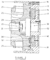
- FIG. 1 is shown schematically in vertical section a generator set comprising on the one hand a heat engine 10 and on the other hand an electric generator composed of a rotor 30 rotating in front of a stator 40.
- This heat engine 10 may be petrol, but preferably is a diesel engine, in particular a single-cylinder diesel engine operating with several types of fuel such as fuel oil, diesel, vegetable oil or the like.
- a piston articulated at the end of a connecting rod and sliding inside its cylinder The other end of the connecting rod is mounted in rotation on a crankshaft 22 also carried in rotation by two bearings 11 within the crankcase 12.
- the extension 22 'of the crankshaft facing the right in the figure therefore constitutes the mechanical output shaft of the heat engine 10.
- the heat engine 10 further comprises a flywheel 20 mounted on the mechanical outlet 22 'of the crankshaft by which it is directly driven in rotation.
- this flywheel 20 is contained inside an adaptation flange 14 extending the motor casing 12.
- a cover 18 fixed by screws 16 to the flange adapter 14 closes the enclosure containing the flywheel 20.
- advantage is taken of the rotation of the flywheel 20 opposite the cover 18 to arrange a generator there electric power.
- This electric generator comprises on the one hand a rotor 30 in the form a circular metallic flat crown, this plate being notably constituted by a sheet metal machined in turning, milling and drilling and to which a surface treatment to avoid oxidation. Milling has made it possible in particular to clear a cavity 38 in the form of a circular crown in the front face coaxial median. Sixteen groups are glued and resinated in this cavity of permanent magnets 32 at the cobalt samarium, each group of magnets having a circular sector shape. This rotor assembly is then balanced dynamically.
- this rotor 30 is fixed to the end of the crankshaft 22 '22 by fixing screws 36, being well understood that this rotor 30 could also have been fixed directly to the flywheel 20 by fixing screws 36 '.
- the diameter of the rotor plate is around 280 mm for a thickness of the order of 15 mm.
- the permanent lovers then have a depth of the order of 5 mm for a radial height of the order of 35 mm, the angle at the top of the circular sector of a magnet being of the order of 22 degrees.
- the generator according to the invention further comprises a stator 40 also having the general form of a circular crown.
- the circuit magnetic of this stator is in particular made from a silicon strip to oriented grains, cut out of notches, then rolled and butt welded to form a very compact crown with a series of side-by-side oriented poles radially and axially in the direction of the stator. Around these poles are mounted armature wafers, their number and number of turns depending on the desired frequency and voltage.
- the entire stator 40 is then impregnated and molded in a protective resin 41 resistant to vibrations, thermal shocks and high temperatures.
- this crown of stator 40 is screwed directly against the internal face of the cover 18 by screws attachment 42, and this very exactly opposite the rotor 30, that is to say coaxially at the outlet 22 'of the crankshaft 22.
- the stator has a diameter of around 250 mm for a thickness of around 28 mm.
- the generator set also includes control electronics and regulation made up of six main circuits.
- the first circuit constitutes a PLC to start the engine with the ignition key, or automatically by lack of power on the network, or by an external order. This automaton also allows monitoring of engine overspeed or underspeed, pressure and oil temperature.
- the second circuit constitutes a loop regulation to activate the flow rate of the diesel engine injection pump by through an electric actuator and a current sensor doing so vary the speed of the motor depending on the power used.
- the third circuit is a power inverter working by programming or by switching to reconstruct a well-defined voltage and frequency at the output, and this with a perfect sinusoid.
- the control electronics can include also a fourth charging and monitoring circuit for mounted batteries in buffer, a fifth overload and short-circuit protection circuit in input and / or in output and a sixth filtering circuit also in input and out.
- FIG 2 is illustrated a second more elaborate embodiment of the electric generator integrated at the end of the heat engine according to the invention.
- a circular cavity 38 is milled directly in the front face of the inertia flywheel 21, cavity in which are installed the permanent lovers 32.
- the internal rear part of the flywheel 21 comprises a plurality of fins 25 giving this flywheel a function additional fan. This flywheel therefore creates an air flow which can then be directed towards the cylinder of the engine for the cool.
- this inertia flywheel 21 is mounted at the end 23 of crankshaft by means of a fixing nut 33, a key 29 ensuring rotational drive.
- This rotor has an external diameter of the order of 300 mm for a thickness of the order of 50 mm, the fins having a width of around 80 mm.
- the cover 13 is molded or machined so as to include in the mass an annular housing 15 in which is directly integrated and embedded stator winding 40.
- the outer diameter of the cover is here of the order of 350 mm corresponding to the external diameter of the flange 14.
- the thickness of this cover is of the order of 60 mm, the cavity 15 for housing stator 40 having a depth of the order of 30 mm.
- the dimensions mentioned above ensure sufficient rigidity of the generator so as to be able to minimize the air gap as much as possible, in particular reduce it to around 0.6 mm.
- the force of attraction generated within the generator can go up to 850 kgf, and it should then to reinforce the bearings and the bearing stop of the crankshaft within the engine thermal.
- a series of circular grooves can also be provided 17 concentric in the external face of the stator cover 13, these grooves thus forming between them a series of generator cooling fins.
- the heat engine 10 is preferably a single cylinder diesel engine for cost considerations but can also be a multi-cylinder diesel engine, or even a gasoline engine with one or more cylinders.
- the art knows how to resize the constituent parts in adequate ratios.
- This generator can thus, thanks to its converter, produce a voltage of 115 volts at 400 hertz for a power of 9 kVA three-phase or 110 volts at 200 hertz for a power of 4.5 kVA three-phase or 42 volts at 200 hertz for a power of 4.5 kVA three-phase, or even a direct voltage of 48 volts, 125 amps, for a power of 6 kVA DC.
- Such compact generators can find multiple applications, particularly in the aeronautical, marine, but also within telecommunication cabinets or as battery chargers. It is also possible to mount such a compact generator set within a hybrid vehicle. It can also be used in cogeneration. This group generator is most of the time used in public works either for lighting, or to implement tools.
Landscapes
- Engineering & Computer Science (AREA)
- Chemical & Material Sciences (AREA)
- Combustion & Propulsion (AREA)
- Mechanical Engineering (AREA)
- General Engineering & Computer Science (AREA)
- Power Engineering (AREA)
- Connection Of Motors, Electrical Generators, Mechanical Devices, And The Like (AREA)
- Permanent Magnet Type Synchronous Machine (AREA)
Priority Applications (2)
| Application Number | Priority Date | Filing Date | Title |
|---|---|---|---|
| EP97420148A EP0898352A1 (de) | 1997-08-22 | 1997-08-22 | Generatorsatz |
| EP98420120A EP0898353A1 (de) | 1997-08-22 | 1998-07-15 | Generatorsatz |
Applications Claiming Priority (1)
| Application Number | Priority Date | Filing Date | Title |
|---|---|---|---|
| EP97420148A EP0898352A1 (de) | 1997-08-22 | 1997-08-22 | Generatorsatz |
Publications (1)
| Publication Number | Publication Date |
|---|---|
| EP0898352A1 true EP0898352A1 (de) | 1999-02-24 |
Family
ID=8229958
Family Applications (1)
| Application Number | Title | Priority Date | Filing Date |
|---|---|---|---|
| EP97420148A Withdrawn EP0898352A1 (de) | 1997-08-22 | 1997-08-22 | Generatorsatz |
Country Status (1)
| Country | Link |
|---|---|
| EP (1) | EP0898352A1 (de) |
Cited By (12)
| Publication number | Priority date | Publication date | Assignee | Title |
|---|---|---|---|---|
| EP1057985B1 (de) * | 1999-05-31 | 2005-10-19 | Nortron ApS | Kompakte Vorrichtung und ein Verfahren zur Krafterzeugung |
| CN102678304A (zh) * | 2011-03-10 | 2012-09-19 | 湖南华强电气有限公司 | 一种汽车发动机 |
| CN102678306A (zh) * | 2011-03-10 | 2012-09-19 | 湖南华强电气有限公司 | 一种汽车发动机 |
| CN102678316A (zh) * | 2011-03-10 | 2012-09-19 | 湖南华强电气有限公司 | 一种汽车发动机 |
| US8496079B2 (en) | 2009-09-16 | 2013-07-30 | Swissauto Powersport Llc | Electric vehicle and on-board battery charging apparatus therefore |
| US9187083B2 (en) | 2009-09-16 | 2015-11-17 | Polaris Industries Inc. | System and method for charging an on-board battery of an electric vehicle |
| US9535481B2 (en) | 2012-02-20 | 2017-01-03 | Engineered Electric Company | Power grid remote access |
| CN107458333A (zh) * | 2017-08-02 | 2017-12-12 | 江西清华泰豪三波电机有限公司 | 车辆嵌入式发电系统与汽车 |
| US10744868B2 (en) | 2016-06-14 | 2020-08-18 | Polaris Industries Inc. | Hybrid utility vehicle |
| US10780770B2 (en) | 2018-10-05 | 2020-09-22 | Polaris Industries Inc. | Hybrid utility vehicle |
| US11370266B2 (en) | 2019-05-16 | 2022-06-28 | Polaris Industries Inc. | Hybrid utility vehicle |
| CN115387902A (zh) * | 2021-10-15 | 2022-11-25 | 常州市沃拓机电有限公司 | 一种柴油发电机 |
Citations (2)
| Publication number | Priority date | Publication date | Assignee | Title |
|---|---|---|---|---|
| US2715685A (en) * | 1953-03-23 | 1955-08-16 | Arthur E Brown | Dynamo-electric machine and reciprocable power unit therefor |
| AT390127B (de) * | 1984-07-27 | 1990-03-26 | J Blaschke Fa | Tragbares dieselmotor-generator-pumpenaggregat |
-
1997
- 1997-08-22 EP EP97420148A patent/EP0898352A1/de not_active Withdrawn
Patent Citations (2)
| Publication number | Priority date | Publication date | Assignee | Title |
|---|---|---|---|---|
| US2715685A (en) * | 1953-03-23 | 1955-08-16 | Arthur E Brown | Dynamo-electric machine and reciprocable power unit therefor |
| AT390127B (de) * | 1984-07-27 | 1990-03-26 | J Blaschke Fa | Tragbares dieselmotor-generator-pumpenaggregat |
Cited By (14)
| Publication number | Priority date | Publication date | Assignee | Title |
|---|---|---|---|---|
| EP1057985B1 (de) * | 1999-05-31 | 2005-10-19 | Nortron ApS | Kompakte Vorrichtung und ein Verfahren zur Krafterzeugung |
| US8496079B2 (en) | 2009-09-16 | 2013-07-30 | Swissauto Powersport Llc | Electric vehicle and on-board battery charging apparatus therefore |
| US9187083B2 (en) | 2009-09-16 | 2015-11-17 | Polaris Industries Inc. | System and method for charging an on-board battery of an electric vehicle |
| CN102678304A (zh) * | 2011-03-10 | 2012-09-19 | 湖南华强电气有限公司 | 一种汽车发动机 |
| CN102678306A (zh) * | 2011-03-10 | 2012-09-19 | 湖南华强电气有限公司 | 一种汽车发动机 |
| CN102678316A (zh) * | 2011-03-10 | 2012-09-19 | 湖南华强电气有限公司 | 一种汽车发动机 |
| US9535481B2 (en) | 2012-02-20 | 2017-01-03 | Engineered Electric Company | Power grid remote access |
| US9552029B2 (en) | 2012-02-20 | 2017-01-24 | Engineered Electric Company | Micro grid power distribution unit |
| US10744868B2 (en) | 2016-06-14 | 2020-08-18 | Polaris Industries Inc. | Hybrid utility vehicle |
| CN107458333A (zh) * | 2017-08-02 | 2017-12-12 | 江西清华泰豪三波电机有限公司 | 车辆嵌入式发电系统与汽车 |
| US10780770B2 (en) | 2018-10-05 | 2020-09-22 | Polaris Industries Inc. | Hybrid utility vehicle |
| US11370266B2 (en) | 2019-05-16 | 2022-06-28 | Polaris Industries Inc. | Hybrid utility vehicle |
| CN115387902A (zh) * | 2021-10-15 | 2022-11-25 | 常州市沃拓机电有限公司 | 一种柴油发电机 |
| CN115387902B (zh) * | 2021-10-15 | 2024-01-02 | 常州市沃拓机电有限公司 | 一种柴油发电机 |
Similar Documents
| Publication | Publication Date | Title |
|---|---|---|
| EP0183576B1 (de) | Drehende Maschine mit Permanentmagneten | |
| EP1177611A1 (de) | Mehrphasige rotierende elektrische maschine | |
| EP0898352A1 (de) | Generatorsatz | |
| FR2582164A1 (fr) | Alternateur-compresseur a excitation par aimant permanent et a commande en courant continu | |
| FR2835114A1 (fr) | Rotor hybride pour alternateur | |
| FR2865322A1 (fr) | Machine dynamoelectrique a courant alternatif | |
| EP2656487A2 (de) | Spannungsregler für eine elektrische drehmaschine, lager für eine solche maschine mit einer solchen vorrichtung und solche maschine mit einem lager | |
| EP2656486B1 (de) | Spannungsregler für eine elektrische drehmaschine, lager für eine solche maschine mit einer solchen vorrichtung und solche maschine mit einem lager | |
| FR2857518A1 (fr) | Machine dynamoelectrique a rotor a poles a griffes a deux bobines et dephasage du stator | |
| EP0898353A1 (de) | Generatorsatz | |
| EP1076411B1 (de) | Vorrichtung zur Produktion von Elektrizität | |
| FR2898082A1 (fr) | Agencement d'une machine electrique tournante dans un moteur a combustion interne et vehicule automobile comportant un tel agencement d'un moteur thermique et d'une machine electrique. | |
| FR2641139A1 (de) | ||
| FR2919971A1 (fr) | Generateur electrique et installation comportant une tour d'eclairage alimentee par un tel generateur | |
| WO2000066991A1 (fr) | Machine de charge pour un banc d'essai d'un moteur thermique | |
| FR2547124A1 (fr) | Machine dynamo-electrique sans balais a ensemble de roue de commande ameliore | |
| EP3170688B1 (de) | Einheit bestehend aus einem generator und elektromotoren für ein klimatisierungs- oder kühlsystem eines fahrzeugs | |
| FR3103653A1 (fr) | Machine électrique tournante avec blocage axial du stator | |
| EP2541735B1 (de) | Rotor einer multipolaren elektrischen Synchronmaschine mit Schenkelpolen | |
| FR3098041A1 (fr) | Machine electrique tournante à refroidissement par huile | |
| FR3058846B1 (fr) | Machine electrique tournante comprenant un arbre de rotor et un roulement | |
| FR3109037A1 (fr) | Capot pour une machine électrique tournante | |
| FR3098040A1 (fr) | Machine electrique tournante à refroidissement par eau | |
| WO2023166442A1 (fr) | Moteur électromagnétique à aimants surfaciques | |
| EP2879274B1 (de) | Elektromaschine zum Antrieb eines elektrischen Kompressors und elektrischer Kompressor mit einer derartigen elektrischen Maschine |
Legal Events
| Date | Code | Title | Description |
|---|---|---|---|
| PUAI | Public reference made under article 153(3) epc to a published international application that has entered the european phase |
Free format text: ORIGINAL CODE: 0009012 |
|
| AK | Designated contracting states |
Kind code of ref document: A1 Designated state(s): AT BE CH DE DK ES FI FR GB GR IE IT LI LU MC NL PT SE |
|
| AX | Request for extension of the european patent |
Free format text: AL;LT;LV;RO;SI |
|
| AKX | Designation fees paid | ||
| STAA | Information on the status of an ep patent application or granted ep patent |
Free format text: STATUS: THE APPLICATION IS DEEMED TO BE WITHDRAWN |
|
| 18D | Application deemed to be withdrawn |
Effective date: 19990825 |
|
| REG | Reference to a national code |
Ref country code: DE Ref legal event code: 8566 |