US9535481B2 - Power grid remote access - Google Patents
Power grid remote access Download PDFInfo
- Publication number
- US9535481B2 US9535481B2 US13/772,218 US201313772218A US9535481B2 US 9535481 B2 US9535481 B2 US 9535481B2 US 201313772218 A US201313772218 A US 201313772218A US 9535481 B2 US9535481 B2 US 9535481B2
- Authority
- US
- United States
- Prior art keywords
- power
- network
- generators
- distribution unit
- data
- Prior art date
- Legal status (The legal status is an assumption and is not a legal conclusion. Google has not performed a legal analysis and makes no representation as to the accuracy of the status listed.)
- Active, expires
Links
Images


Classifications
-
- G—PHYSICS
- G06—COMPUTING OR CALCULATING; COUNTING
- G06F—ELECTRIC DIGITAL DATA PROCESSING
- G06F1/00—Details not covered by groups G06F3/00 - G06F13/00 and G06F21/00
- G06F1/26—Power supply means, e.g. regulation thereof
- G06F1/28—Supervision thereof, e.g. detecting power-supply failure by out of limits supervision
-
- H—ELECTRICITY
- H02—GENERATION; CONVERSION OR DISTRIBUTION OF ELECTRIC POWER
- H02J—ELECTRIC POWER NETWORKS; CIRCUIT ARRANGEMENTS OR SYSTEMS FOR SUPPLYING OR DISTRIBUTING ELECTRIC POWER; SYSTEMS FOR STORING ELECTRIC ENERGY
- H02J3/00—Circuit arrangements for AC mains or AC distribution networks
- H02J3/17—Demand-responsive operation of AC power transmission or distribution networks
-
- G—PHYSICS
- G05—CONTROLLING; REGULATING
- G05B—CONTROL OR REGULATING SYSTEMS IN GENERAL; FUNCTIONAL ELEMENTS OF SUCH SYSTEMS; MONITORING OR TESTING ARRANGEMENTS FOR SUCH SYSTEMS OR ELEMENTS
- G05B15/00—Systems controlled by a computer
-
- H—ELECTRICITY
- H02—GENERATION; CONVERSION OR DISTRIBUTION OF ELECTRIC POWER
- H02J—ELECTRIC POWER NETWORKS; CIRCUIT ARRANGEMENTS OR SYSTEMS FOR SUPPLYING OR DISTRIBUTING ELECTRIC POWER; SYSTEMS FOR STORING ELECTRIC ENERGY
- H02J3/00—Circuit arrangements for AC mains or AC distribution networks
- H02J3/04—Arrangements for connecting networks of the same frequency but supplied from different sources
- H02J3/06—Controlling the transfer of power between connected networks; Controlling load sharing between connected networks
-
- H—ELECTRICITY
- H02—GENERATION; CONVERSION OR DISTRIBUTION OF ELECTRIC POWER
- H02J—ELECTRIC POWER NETWORKS; CIRCUIT ARRANGEMENTS OR SYSTEMS FOR SUPPLYING OR DISTRIBUTING ELECTRIC POWER; SYSTEMS FOR STORING ELECTRIC ENERGY
- H02J3/00—Circuit arrangements for AC mains or AC distribution networks
- H02J3/12—Arrangements for adjusting voltage in AC networks by changing a characteristic of the network load
- H02J3/14—Arrangements for adjusting voltage in AC networks by changing a characteristic of the network load by switching loads on to, or off from, the networks, e.g. progressively balanced loading
-
- H—ELECTRICITY
- H02—GENERATION; CONVERSION OR DISTRIBUTION OF ELECTRIC POWER
- H02J—ELECTRIC POWER NETWORKS; CIRCUIT ARRANGEMENTS OR SYSTEMS FOR SUPPLYING OR DISTRIBUTING ELECTRIC POWER; SYSTEMS FOR STORING ELECTRIC ENERGY
- H02J3/00—Circuit arrangements for AC mains or AC distribution networks
- H02J3/38—Arrangements for feeding a single network from two or more generators or sources in parallel; Arrangements for feeding already energised networks from additional generators or sources in parallel
-
- H—ELECTRICITY
- H02—GENERATION; CONVERSION OR DISTRIBUTION OF ELECTRIC POWER
- H02J—ELECTRIC POWER NETWORKS; CIRCUIT ARRANGEMENTS OR SYSTEMS FOR SUPPLYING OR DISTRIBUTING ELECTRIC POWER; SYSTEMS FOR STORING ELECTRIC ENERGY
- H02J2105/00—Networks for supplying or distributing electric power characterised by their spatial reach or by the load
- H02J2105/50—Networks for supplying or distributing electric power characterised by their spatial reach or by the load for selectively controlling the operation of the loads
- H02J2105/51—Networks for supplying or distributing electric power characterised by their spatial reach or by the load for selectively controlling the operation of the loads according to a condition being electrical
-
- Y—GENERAL TAGGING OF NEW TECHNOLOGICAL DEVELOPMENTS; GENERAL TAGGING OF CROSS-SECTIONAL TECHNOLOGIES SPANNING OVER SEVERAL SECTIONS OF THE IPC; TECHNICAL SUBJECTS COVERED BY FORMER USPC CROSS-REFERENCE ART COLLECTIONS [XRACs] AND DIGESTS
- Y02—TECHNOLOGIES OR APPLICATIONS FOR MITIGATION OR ADAPTATION AGAINST CLIMATE CHANGE
- Y02B—CLIMATE CHANGE MITIGATION TECHNOLOGIES RELATED TO BUILDINGS, e.g. HOUSING, HOUSE APPLIANCES OR RELATED END-USER APPLICATIONS
- Y02B70/00—Technologies for an efficient end-user side electric power management and consumption
- Y02B70/30—Systems integrating technologies related to power network operation and communication or information technologies for improving the carbon footprint of the management of residential or tertiary loads, i.e. smart grids as climate change mitigation technology in the buildings sector, including also the last stages of power distribution and the control, monitoring or operating management systems at local level
- Y02B70/3225—Demand response systems, e.g. load shedding, peak shaving
-
- Y—GENERAL TAGGING OF NEW TECHNOLOGICAL DEVELOPMENTS; GENERAL TAGGING OF CROSS-SECTIONAL TECHNOLOGIES SPANNING OVER SEVERAL SECTIONS OF THE IPC; TECHNICAL SUBJECTS COVERED BY FORMER USPC CROSS-REFERENCE ART COLLECTIONS [XRACs] AND DIGESTS
- Y04—INFORMATION OR COMMUNICATION TECHNOLOGIES HAVING AN IMPACT ON OTHER TECHNOLOGY AREAS
- Y04S—SYSTEMS INTEGRATING TECHNOLOGIES RELATED TO POWER NETWORK OPERATION, COMMUNICATION OR INFORMATION TECHNOLOGIES FOR IMPROVING THE ELECTRICAL POWER GENERATION, TRANSMISSION, DISTRIBUTION, MANAGEMENT OR USAGE, i.e. SMART GRIDS
- Y04S20/00—Management or operation of end-user stationary applications or the last stages of power distribution; Controlling, monitoring or operating thereof
- Y04S20/20—End-user application control systems
- Y04S20/222—Demand response systems, e.g. load shedding, peak shaving
Definitions
- the embodiments described herein relate generally to power generator systems. More particularly, the embodiments relate to forming a power grid array of multiple power generators coupled with a power distribution unit.
- a micro-grid (or “microgrid”) is a localized grouping of electricity generators, energy storage, and electrical loads that normally operate connected to a traditional centralized grid (“macrogrid”). Power generation and the electrical loads in a microgrid are usually interconnected at low voltage. From the point of view of the grid operator, a connected microgrid can be controlled as if it was one entity. Microgrid generation resources can include fuel cells, wind, solar, or other energy sources, including local power generators. The multiple dispersed generation sources and ability to isolate the microgrid from a larger network can provide highly reliable electric power.
- Power grid systems generally require load profile data including the operating characteristics of all of the power generators connected to the grid to be gathered and analyzed to optimize the microgrid's configuration. But, heretofore, during normal operation of microgrids, information about the load characteristics and generator performance is not normally available without connecting it with external equipment and custom software.
- conventional generators typically include a display to observe performance characteristics, fault conditions, oil pressure data, and the like; however, the data is never stored anywhere so it is lost when the generator is shut down or a user clears the fault or warning conditions.
- microgrids are more fuel efficient than standalone or parallel generator systems and they provide a robust, redundant power source. But microgrids are generally more complex. As a result, conventional microgrid systems require that entire networks (e.g., micro-grid arrays) be shut down to disconnect one generator from the grid for servicing.
- Embodiments described herein include systems, methods, and apparatuses for forming a power grid array comprising multiple power generators coupled together with a power distribution unit such that the operational data from each of the power generators can be monitored and the performance of the power grid can be optimized. In one embodiment, this is accomplished using a computer built into the power distribution unit. This operational data can then be stored and accessed later for analysis to optimize the power grid array's configuration. The operational data of the generators in the power grid can be used to perform load balancing among the generators to coordinate the amount of power each of the generators should contribute to the electrical load. For instance, the operational data can be used to automatically shut down one or more of the connected generators to conserve fuel or to accommodate a changing electrical load profile.
- the power output lines from each of the plurality of generators in the power grid array can be coupled together using a load sharing cable to drive the overall electrical load of the power grid.
- a safety wire is embedded into each of the power output lines of the generators to ensure that each generator connected thereto is disabled when it is shut down.
- Embodiments described herein are also adapted to form a microgrid network within the power grid array that provides a means of communication among the power distribution unit's computer and the multiple generators in the array. This communication facilitates monitoring of the power grid as well as receiving and storing the operational data from each of the generators in the grid.
- the microgrid network can then be used to communicate the operational data over one or more connected networks via a network port coupled with the power distribution unit (“PDU”) computer that allows users to remotely access the power grid and to monitor the operational characteristics of the generators. Users can access the microgrid using a data processing device of some kind, such as a laptop computer, tablet, or a mobile communications device. A hardwired connection or a wireless router can be plugged into the network port for remote access.
- the network port exposes the operational data as a web server that can be accessed on the Internet.
- the network port can be further adapted to receive commands from the user's device over the network for controlling the generators in the grid.
- FIG. 1 depicts an example block diagram of a power generator system according to one illustrative embodiment.
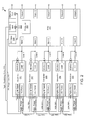
- FIG. 2 depicts an example block diagram of a power distribution unit coupled with a plurality of power generators in a power grid array according to one illustrative embodiment.
- FIG. 3A depicts an example flow chart of a process of monitoring and controlling a power grid array according to one illustrative embodiment.
- FIG. 3B depicts an example flow chart of a process of forming a microgrid network in a power grid array according to one illustrative embodiment.
- FIG. 4A depicts an example screen shot of display for monitoring power generators in a power grid according to one illustrative embodiment.
- FIG. 4B depicts an example screen shot of display for accessing power generators in a power grid according to one illustrative embodiment.
- FIG. 4C depicts an example screen shot of display showing the operational characteristics of a power generator in a power grid according to one illustrative embodiment.
- FIG. 4D depicts a second example screen shot of display showing additional operational characteristics of a power generator in a power grid according to one illustrative embodiment.
- FIG. 5 depicts an example block diagram of a data processing system upon which the disclosed embodiments may be implemented in certain embodiments.
- the techniques introduced herein are adapted to form a power grid array by coupling together a plurality of power generators with a power distribution unit such that the operational data from each of the power generators can be monitored, analyzed, and optimized. In one embodiment, this is accomplished using a computer built into the power distribution unit. This operational data can then be stored and accessed later for analysis to optimize the microgrid's configuration.
- the operational data of the generators in the power grid can be used to perform load balancing among the power generators in the grid to coordinate the amount of power each of the generators should contribute to the electrical load. For instance, the data can also be used to automatically shut down one or more of the connected generators to conserve fuel.
- the techniques described herein are also adapted to form a microgrid network within the power grid array that provides a means of communication among the power distribution unit's computer and the multiple generators in the array. This communication facilitates monitoring of the power grid as well as receiving and storing the operational data from each of the generators in the grid.
- the microgrid network can then be used to communicate the operational data to the computer in the power distribution unit as well as over one or more connected networks via a network port coupled with the computer.
- the microgrid network thus facilitates users to remotely access the power grid using a data processing device of some sort, and to monitor the operational characteristics of the generators.
- users can access the microgrid network using a laptop computer, tablet, or a mobile communications device as examples. Other devices, computers, or data processing devices can be used.
- a hardwired connection or a wireless router can be plugged into the network port for remote access.
- the network port exposes the operational data as a web server that can be accessed on the Internet.
- the network port can be further adapted to receive commands from the user's device over the network for controlling the generators in the grid.
- the microgrid network is accessed using an Internet Protocol (“IP”) address of the power grid array.
- IP Internet Protocol
- the computer of the power distribution unit can also be accessed by its IP address.
- the power distribution unit is capable of monitoring all of the generators in the power grid with a single computer (or multiple computers in some embodiments).
- the power grid data can be monitored remotely by users using various data processing devices (e.g., laptop, PDA, table PC, smart phone, etc.).
- the power grid data can be shared on a network such as a LAN, WAN, or other network configuration. Users can access a hard drive of the PDU by its IP address and download or view power grid data without preloading any particular software onto the user's device.
- the data can be in spreadsheet format, document format, or other commercially available or proprietary format. The user can view, download, and manipulate data once access to the PDU is established. Security measures may be implemented as required as would be appreciated by one of ordinary skill in the art.
- the PDU includes a computer that accesses and collects the operational data from one or more of the gensets.
- each of the generators in the grid has a built-in computer that collects and stores the operational data and can communicate and share the data over the microgrid network via a wired or wireless connection.
- a control panel inside each generator can be configured to export the operation data to the PDU.
- Certain embodiments incorporate grid monitoring Ethernet connections and automatic data logging using the computer built into the PDU.
- the monitoring can begin at the time the power grid is brought online.
- the data logging computer can also detect new generators when they are attached to the grid and can then log data from those additional computers as they are brought online. In certain embodiments, this can be accomplished using an integrated controller area network (“CAN”) bus interfaced with a Modbus for the operational data monitoring.
- the PDU computer can log operational data from connected generators to a solid state disk (or other memory) and can be remotely accessed to view and download the data over a network connection such as an Ethernet connection.
- the network port (e.g., Ethernet port) can be connected to the user's data processing device over a wired or wireless network.
- the user's device can be a tablet PC, laptop, or smart phone application connected via an external wireless router for wireless access to the operational data from a remote location.
- FIG. 1 depicts an example block diagram of a power generator system.
- generator 100 includes a controller 105 coupled with a battery 110 to provide DC power 102 to the controller from a DC power connector 103 via a DC power receptacle 106 .
- Controller 105 is further coupled with a digital signal 101 received on a digital signaling cable (not shown) via a digital receptacle 104 .
- only the amount of DC power 102 necessary to charge the battery 110 that powers the controller 105 is provided for each power generator 101 in the power grid. This is advantageous because power can be conserved within the power grid.
- digital signal 101 coupled with the controller 105 via receptacle 104 is used for data and control signals for communications among and between the generators connected to the power grid as well as the computer at the PDU.
- the operational data gathered and stored by the controller 105 can be sent to the PDU computer for monitoring and analysis using the digital signaling cable upon which the digital signal 101 is coupled to.
- the controller 105 of generator 101 can be used to couple the power generated by the generator to the load 117 via load line 120 .
- the load line 120 is referred to as a power output cable of the generator 101 .
- This embodiment further shows that a safety wire 130 coupled with the power output load line 120 of the generator via an interlock receptacle 115 .
- the safety wire 130 and the power output load line 120 are incorporated into the same cable.
- FIG. 2 depicts an example block diagram of a power distribution unit coupled with a plurality of power generators in a power grid array.
- the power grid array includes a plurality of generators 201 - 205 coupled with inputs 1 through 5 of PDU 255 via power output load cables 1 through 5 respectively.
- Generators 201 - 205 each include the components of generator 101 discussed above with respect to FIG. 1 .
- DC power can be coupled to the generators 201 - 205 via the DC power line 252 . As discussed previously, this DC power may be used to charge the batteries of the generators.
- the DC power over line 252 can also be used to power up the computer 260 onboard the PDU 255 via the DC input 230 .
- Other sources of power are also contemplated within the scope of the techniques described herein.
- PDU 255 includes a set of outputs 1 through 5 , which in at least certain embodiments, are adapted to provide low-level power distribution to end users directly from a plurality of the outputs of the power distribution unit. PDU 255 is configured to provide this low-level without requiring additional PDUs connected at the outputs 1 to 5 as is required in conventional systems.
- the digital signal 101 discussed above can be provided over the digital paralleling cable 250 , which is coupled to the digital input of each of the power generators in the power grid as well as to a control input 231 of the PDU 255 .
- This digital signaling cable 250 provides communications within the power grid among the generators 201 - 205 as well as the computer 260 of the PDU via control input 231 .
- the digital communications are used to provide the operational data of the generators 201 - 205 to the PDU for monitoring, storage, and analysis.
- the computer 260 can then provide the operational data and other characteristic data for the generators in the array via a network port such as Ethernet port 232 .
- commands can be received from users over a network coupled with the network port 252 to control certain functionality of the generators connected to the power grid.
- a microgrid network can be established within the power grid array such that operational data can be collected, stored, and provided to users over a wired or wireless connection; and likewise, command and control signals can be received from users remotely over one or more connected networks.
- FIG. 3A depicts an example flow chart of a process of monitoring and controlling a power grid array.
- process 300 begins at operation 301 .
- a power grid array is formed by coupling multiple generators together with the power distribution unit of the present disclosure. This allows the computer on the power distribution unit to monitor the power grid array (operation 302 ) and to receive operational data from the connected generators (operation 303 ). The operational data can then be stored (operation 304 ) and used to analyze, optimize, and control the generators in the power grid (operation 305 ).
- the multiple generators can be synchronized automatically using the techniques described herein such that the amount of power contributed by each of the generators can be coordinated to drive an electrical load profile.
- This operational data can be saved as log files in memory of the computer in the power distribution unit.
- the operational data can further be used to balance the electrical load among the multiple generators and can be used to determine that one or more of the generators should be shut down to conserve fuel or to adapt to a changing electrical load profile.
- FIG. 3B depicts an example flow chart of a process of forming a microgrid network in a power grid array.
- a microgrid network is formed within the power grid array (operation 311 ).
- the power grid array is formed by coupling multiple generators together with the power distribution unit of the present disclosure. This arrangement allows the computer on the power distribution unit to monitor the power grid array (operation 312 ) and to store operational data received from the connected generators in the power grid (operation 313 ). Once the operational data is stored at the PDU, it can be communicated over a network (operations 314 ).
- commands for controlling the generators in the power grid array can also be received from users over the network using a data processing device coupled with the network.
- this can be done by coupling the microgrid network with a network port configured to communicate over one or more networks.
- the network port can be configured to plug into a wireless router to transfer data via Wi-Fi, Bluetooth, or equivalent network.
- the network port is an Ethernet port and the communications can be made over the Internet.
- the network port can be configured to connect to a wired or wireless connection for remote access by a user having a data processing device capable of sending and receiving data over a network.
- the microgrid network can be accessed via a wireless network to view or download the operational data wirelessly from a user's device.
- the network port exposes the operational data of the microgrid network as a web server that can be accessed over the Internet.
- the microgrid network can be accessed, for example, using an Internet Protocol (“IP”) address associated with the power grid array.
- IP Internet Protocol
- the computer in the PDU can also be accessed by its IP address.
- Such access to users on a network can be provided in certain embodiments without preloading any specialized software onto the user's device. This completes process 300 according to one example embodiment.
- the monitoring tracking capabilities described above can provide a pre-alert of a potential problem prior to generator failure.
- Statistical analysis of generator usage over time can provide myriad means of improved generator usage in terms of efficiency, diagnostics, preventative maintenance, and the like.
- the oil pressure in a generator may be low for six weeks followed by a seized motor. The customer may try to return the generator to the manufacturer for a refund claiming that the generator was defective. With access to the generator operational data, the manufacturer is able to determine that, for example, the customer neglected to address the low oil pressure during the prior six-week period and failed to add any oil, which may be useful to know to establish liability.
- a service person can access data trends over time to determine if there is an oil leak, the generator is burning oil, the water temperature is too high, extra fuel is being burned, or the like.
- this type of data is fleeting (e.g., passes in real time) and is then lost.
- the generators or PDU can automatically collect this data and provide operational data trends over time to help diagnose potential problems, or to analyze the data offline or at another time.
- the service person could also analyze power load profiles over a period of time (e.g., 24 hours) to determine if the generators in the power grid are being properly matched to a given load.
- the generators may be oversized for a small load and thus inefficiently utilized for the particular load profile.
- a service person can access a signature of a load profile over several days. This may be useful when a particular load profile is relatively constant on a day-to-day basis, but then there is one particular day that exhibited anomalous results.
- a generator may provide more current than normal at a military base camp when hot water heaters are powered up in the morning, which may indicate a short or other circuit failure.
- the PDU can wirelessly interface with common consumer electronic devices (e.g., tablet personal computers, smart phones, etc.) to transfer power grid operational data for remote monitoring.
- the PDU can include a computer that collects the operational data and stores it in any suitable format.
- the PDU can automatically begin logging all operation data for the power grid at start up.
- the generators in power grid array can be connected together to share an overall electrical load and to communicate with each other to coordinate how much power each generator should contribute to the load.
- a load sharing cable (not shown) can connect the generators together, allow them to communicate with each other, and enable tracking and monitoring of the operating or performance characteristics data of the generators such as their oil pressure, water temperature, fuel level, generator voltage output, potential faults or warnings (e.g., voltage spikes, over voltage, under frequency, etc.).
- Wireless access to the PDU provides a convenient way to monitor the operation of the power grid remotely from a distance away.
- the PDU provides a capability to connect external Ethernet devices, such as a Wi-Fi router, so that the power grid can be on a wireless grid, wireless network, or hardware network, to allow consumer electronic devices (e.g., iPADTM, iPhoneTM, or the like) to connect to the network and retrieve data.
- an application can be downloaded from a onto the user's device. Such an application can enable a user to type in the IP address of the power grid to gain access for monitoring and downloading of power grid data.
- a user may want a particular generator to run for four (4) hours or the user may want to program the grid such that it automatically selects a particular generator to run based on a number of operating hours it has on it.
- the user's device may show that there are three 45 kW generators on the grid and a 10 kW load to calculate power efficiency and usage data.
- the user's device can be configured to download a log file from the power grid. In some cases, this may be imported into common spread sheet applications (e.g., Excel, Numbers, etc.). Other types of data logs can be exported as well as would be appreciated by one of ordinary skill in the art with the benefit of this disclosure.
- a service person wants to troubleshoot a generator in the grid, that person can view what states the generator has gone through and identify where the problem is.
- This data can be downloaded onto the user's device and reviewed at a later time, or emailed or downloaded to another computer, etc. For example, if a soldier in Afghanistan is on the phone with technical support in the United States, that soldier can email a log file to the support personnel to give them a clear picture of the generator operating history over any desired period of time.
- the user's device can remotely access multiple microgrids provided within wireless range.
- All of the operating and performance characteristics can be made accessible on one or more of the generator screens or the PDU, and can be collected, stored, and cataloged at any time by a computer (e.g., the generator controllers or the onboard computer, or the like).
- a computer e.g., the generator controllers or the onboard computer, or the like.
- Conventional generators typically include a display to observe performance characteristics, fault conditions, oil pressure data, and the like; however, the data is never stored anywhere so it is lost when the generator is shut down or a user clears the fault or warning conditions.
- providing a means to collect the generator data for later analysis provides many advantages.
- the operational data can be accessed via a display on a generator (e.g., on the control panel, on the generator chassis, etc.), on the PDU, or other point on the power grid array.
- FIG. 4A depicts an example screen shot of display for monitoring power generators in a power grid.
- a list 401 of online generators 402 is provided in a main screen 400 A of an application for monitoring the microgrid.
- Generator 2 is rated 403 at 30 KW in the illustrated embodiment.
- Additional performance characteristics 405 are also shown.
- Main screen 400 A further includes a settings tab 409 which can be used, in at least certain embodiments, to drill down into further details of the operational characteristics of the generators connected to the grid.
- FIG. 4B depicts an example screen shot of display for accessing power generators in a power grid.
- settings display screen 400 B includes a field 412 for users to type in the IP address of the power grid to access it over a network using the user's data processing device.
- the power grid is located on a network port 414 of the PDU designated as port 502 .
- a field 422 is also provided for users to type in the IP address of the PDU to access it over a network as well.
- Settings display screen further includes a list of log files 425 that have been previously received from the grid and stored in the PDU.
- FIG. 4C depicts an example screen shot of display showing the operational characteristics of a power generator in a power grid.
- display screen 400 C includes configuration information 431 for one of the generators in the grid.
- Such detailed information, including operational data includes (1) the three-phase voltage 432 of the particular generator, (2) the operating frequency 433 , (3) fuel level 434 (e.g., gas, diesel, propane, etc.), (4) total power generated 435 (as well as power generated for each phase), and (5) a listing of log files 436 that have been previously obtained from the grid and stored in the PDU.
- Display screen 400 C further includes a tab 439 to navigate back up the list of generators.
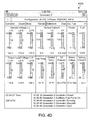
- FIG. 4D depicts a second example screen shot of display showing additional operational characteristics of a power generator in a power grid.
- Other operational data can also be displayed including, but not limited to: (1) which generators are running, which are not; (2) which contactors are supplying power as well as the quantity of power; (3) how much power each generator is contributing to the power grid; (4) the water temperature in the generator radiators; (5) the oil pressure of the generators; (6) systems faults and warnings during operation; (7) the amount of total power available on the power grid; (8) the percentage load on the grid; (9) which generators are contributing to the load and which are not; (10) the total number of hours a generator has been running; (11) overall grid performance including a sum total of all generators; and (13) any real-time or snapshots of the performance of the generator or power grid.
- multiple generators or generator sets (“gensets”) are not directly connected together without some protection device that protects users or equipment from shock hazards.
- two generators can be connected together in parallel where each have both a power cable and a contactor interlock cable (safety cable) for each of the generators.
- kill the power in one generator would be safe since the contactor interlock cable is disconnected and the power could not back feed through to the generator that was powered down.
- power grids with multiple generators and distributed architectures e.g., micro-grid arrays
- the PDU is configured to combine the outputs of all the microgrid connected generators while providing a safe way to disconnect any one generator from the grid for service. This contrasts with conventional systems, which can require that entire networks (e.g., micro-grid arrays) be shut down to disconnect one generator from the grid for servicing.
- the PDU described herein is designed with connectors and cables configured to connect to one or more gensets together and can include internal disconnects (e.g., decouplers) to automatically disconnect the power at power output cables to provide for safe removal of one or more generators from the power grid without having to power down the grid.
- the PDU includes generator isolation control where the power output cable and the safety cable are the same cable.
- Certain embodiments further include failsafe contactor position light-emitting diodes (“LEDs”) or other equivalent indicators to alert users to warn against live voltage on inputs and prevent hazards from failed contactors.
- LEDs failsafe contactor position light-emitting diodes
- a disconnect relay is configured to disconnect the power to the power output cable of one or more generators in the grid while the remaining generators on the grid are still active.
- a micro-grid array may have five generators connected to a PDU, where each one of the generators has an output power cable.
- Each generator can further include five more cables coming for a protected relay via an interlock cable.
- the protection device may be rendered useless because it may be controlled from the wrong generator, thus creating an electrocution hazard.
- the generator power cable may be shut down, the contactor cable can still be powered.
- the techniques described herein resolve this problem in at least certain embodiments by embedding the safety wire in the same cable (or cable connector) as the power cables used to output power to the electrical load.
- the control for the protection device can be combined with the power output cable for the generator making it is impossible that the protection device and the generator will be connected together improperly because both features are incorporated into one cable.
- the PDU includes an automatic disconnect contactor that electrically disconnects a power output cable from the generator when the generator is shut down without requiring manual switches, controls, or the like. This configuration provides a failsafe system that ensures that, when a particular generator is off, the contactor at the remote PDU is also disabled and the power cable is disabled from the PDU back to the generator, which, for all practical purposes, eliminates the risk of electrocution.
- contactor/power cable system includes a lower weight than competing units, improved design of handles that are also used for securing cables, legs that allow for release from muddy surfaces, better impact protection, and failsafe contactor position LEDs that prevent hazards from failed contactors by warning against live voltages on inputs.
- FIG. 5 depicts an example block diagram of a data processing system upon which the disclosed embodiments may be implemented in certain embodiments.
- Embodiments may be practiced with various computer system configurations such as hand-held devices, microprocessor systems, microprocessor-based or programmable user electronics, minicomputers, mainframe computers and the like.
- the embodiments can also be practiced in distributed computing environments where tasks are performed by remote processing devices that are linked through a wire-based or wireless network.
- FIG. 5 shows one example of a data processing system, such as data processing system 500 , which may be used with the present described embodiments. Note that while FIG. 5 illustrates various components of a data processing system, it is not intended to represent any particular architecture or manner of interconnecting the components as such details are not germane to the techniques described herein.
- the data processing system of FIG. 5 may, for example, a personal computer (PC), workstation, tablet, smartphone or other hand-held wireless device, or any device having similar functionality.
- PC personal computer
- workstation tablet
- smartphone hand-held wireless device
- the data processing system 501 includes a system bus 502 which is coupled to a microprocessor 503 , a Read-Only Memory (ROM) 507 , a volatile Random Access Memory (RAM) 505 , as well as other nonvolatile memory 506 .
- microprocessor 503 is coupled to cache memory 504 .
- System bus 502 can be adapted to interconnect these various components together and also interconnect components 503 , 507 , 505 , and 506 to a display controller and display device 508 , and to peripheral devices such as input/output (“I/O”) devices 510 .
- I/O input/output
- I/O devices can include keyboards, modems, network interfaces, printers, scanners, video cameras, or other devices well known in the art.
- I/O devices 510 are coupled to the system bus 502 through I/O controllers 509 .
- the I/O controller 509 includes a Universal Serial Bus (“USB”) adapter for controlling USB peripherals or other type of bus adapter.
- USB Universal Serial Bus
- RAM 505 can be implemented as dynamic RAM (“DRAM”) which requires power continually in order to refresh or maintain the data in the memory.
- the other nonvolatile memory 506 can be a magnetic hard drive, magnetic optical drive, optical drive, DVD RAM, or other type of memory system that maintains data after power is removed from the system. While FIG. 5 shows that nonvolatile memory 506 as a local device coupled with the rest of the components in the data processing system, it will be appreciated by skilled artisans that the described techniques may use a nonvolatile memory remote from the system, such as a network storage device coupled with the data processing system through a network interface such as a modem or Ethernet interface (not shown).
- embodiments can employ various computer-implemented functions involving data stored in a data processing system. That is, the techniques may be carried out in a computer or other data processing system in response executing sequences of instructions stored in memory.
- hardwired circuitry may be used independently, or in combination with software instructions, to implement these techniques.
- the described functionality may be performed by specific hardware components containing hardwired logic for performing operations, or by any combination of custom hardware components and programmed computer components.
- the techniques described herein are not limited to any specific combination of hardware circuitry and software.
- Embodiments herein may also be in the form of computer code stored on a computer-readable medium.
- Computer-readable media can also be adapted to store computer instructions, which when executed by a computer or other data processing system, such as data processing system 500 , are adapted to cause the system to perform operations according to the techniques described herein.
- Computer-readable media can include any mechanism that stores information in a form accessible by a data processing device such as a computer, network device, tablet, smartphone, or any device having similar functionality.
- Examples of computer-readable media include any type of tangible article of manufacture capable of storing information thereon such as a hard drive, floppy disk, DVD, CD-ROM, magnetic-optical disk, ROM, RAM, EPROM, EEPROM, flash memory and equivalents thereto, a magnetic or optical card, or any type of media suitable for storing electronic data.
- Computer-readable media can also be distributed over a network-coupled computer system, which can be stored or executed in a distributed fashion.
Landscapes
- Engineering & Computer Science (AREA)
- Power Engineering (AREA)
- General Engineering & Computer Science (AREA)
- Physics & Mathematics (AREA)
- General Physics & Mathematics (AREA)
- Theoretical Computer Science (AREA)
- Automation & Control Theory (AREA)
- Remote Monitoring And Control Of Power-Distribution Networks (AREA)
Abstract
Description
Claims (28)
Priority Applications (2)
| Application Number | Priority Date | Filing Date | Title |
|---|---|---|---|
| US13/772,229 US9552029B2 (en) | 2012-02-20 | 2013-02-20 | Micro grid power distribution unit |
| US13/772,218 US9535481B2 (en) | 2012-02-20 | 2013-02-20 | Power grid remote access |
Applications Claiming Priority (5)
| Application Number | Priority Date | Filing Date | Title |
|---|---|---|---|
| US201261600986P | 2012-02-20 | 2012-02-20 | |
| US201261600987P | 2012-02-20 | 2012-02-20 | |
| US13/400,532 US20130214602A1 (en) | 2012-02-20 | 2012-02-20 | Method and system for generator control |
| US13/772,229 US9552029B2 (en) | 2012-02-20 | 2013-02-20 | Micro grid power distribution unit |
| US13/772,218 US9535481B2 (en) | 2012-02-20 | 2013-02-20 | Power grid remote access |
Publications (2)
| Publication Number | Publication Date |
|---|---|
| US20130238150A1 US20130238150A1 (en) | 2013-09-12 |
| US9535481B2 true US9535481B2 (en) | 2017-01-03 |
Family
ID=49114809
Family Applications (2)
| Application Number | Title | Priority Date | Filing Date |
|---|---|---|---|
| US13/772,218 Active 2034-09-30 US9535481B2 (en) | 2012-02-20 | 2013-02-20 | Power grid remote access |
| US13/772,229 Active 2034-11-17 US9552029B2 (en) | 2012-02-20 | 2013-02-20 | Micro grid power distribution unit |
Family Applications After (1)
| Application Number | Title | Priority Date | Filing Date |
|---|---|---|---|
| US13/772,229 Active 2034-11-17 US9552029B2 (en) | 2012-02-20 | 2013-02-20 | Micro grid power distribution unit |
Country Status (1)
| Country | Link |
|---|---|
| US (2) | US9535481B2 (en) |
Cited By (2)
| Publication number | Priority date | Publication date | Assignee | Title |
|---|---|---|---|---|
| US10114398B2 (en) | 2009-04-24 | 2018-10-30 | Hunter Defense Technologies, Inc. | Mobile micro-grid power system controller and method |
| US10581248B2 (en) | 2017-03-17 | 2020-03-03 | Telia Company Ab | Methods and apparatuses for a microgrid network |
Families Citing this family (15)
| Publication number | Priority date | Publication date | Assignee | Title |
|---|---|---|---|---|
| US9535481B2 (en) | 2012-02-20 | 2017-01-03 | Engineered Electric Company | Power grid remote access |
| US10289080B2 (en) | 2012-10-11 | 2019-05-14 | Flexgen Power Systems, Inc. | Multi-generator applications using variable speed and solid state generators for efficiency and frequency stabilization |
| US9312699B2 (en) | 2012-10-11 | 2016-04-12 | Flexgen Power Systems, Inc. | Island grid power supply apparatus and methods using energy storage for transient stabilization |
| US9553517B2 (en) | 2013-03-01 | 2017-01-24 | Fllexgen Power Systems, Inc. | Hybrid energy storage system and methods |
| US9515491B2 (en) | 2013-09-18 | 2016-12-06 | International Business Machines Corporation | Managing devices within micro-grids |
| US10025363B2 (en) | 2014-12-12 | 2018-07-17 | Intel Corporation | Device agnostic power monitoring and profiling system |
| AU2015374405A1 (en) | 2014-12-30 | 2017-07-20 | Flexgen Power Systems, Inc. | Transient power stabilization device with active and reactive power control |
| CN106096844B (en) * | 2016-06-15 | 2022-03-08 | 中国电力科学研究院 | Method for evaluating demand response physical potential of large feeder of urban power grid |
| CN106787190B (en) * | 2016-12-21 | 2019-03-29 | 北京理工大学 | A monitoring system and monitoring method for a DC microgrid system |
| US10338548B2 (en) * | 2017-04-17 | 2019-07-02 | General Electric Company | Logic based simplex/dual/TMR driver for control outputs |
| US10203373B1 (en) | 2017-11-03 | 2019-02-12 | Honda Motor Co., Ltd | Systems and methods for using profiles to monitor generators |
| US10601226B2 (en) * | 2018-04-04 | 2020-03-24 | Bloom Energy Corporation | Advanced uninterruptable power module controller and method of operating same |
| WO2020014381A1 (en) * | 2018-07-10 | 2020-01-16 | Dd Dannar Llc | Composite power station systems and methods |
| MX2023000824A (en) * | 2020-07-24 | 2023-03-01 | Voltagrid Llc | Common bus switchgear for mobile hybrid micro-grids. |
| US12230965B2 (en) | 2021-12-30 | 2025-02-18 | Smart Wires, Inc. | Power flow control system for a distribution grid having a grid forming capability |
Citations (74)
| Publication number | Priority date | Publication date | Assignee | Title |
|---|---|---|---|---|
| GB234924A (en) | 1924-03-12 | 1925-06-11 | English Electric Co Ltd | Improvements in and connected with the control of the conditions of operation of electric motor generator sets |
| GB319072A (en) | 1928-06-19 | 1929-09-19 | British Thomson Houston Co Ltd | Improvements relating to the control of electric motor generator sets |
| GB856732A (en) | 1956-03-10 | 1960-12-21 | Gen Electric Co Ltd | Improvements in automatic electric switching systems such as automatic telephone exchanges |
| GB1146033A (en) | 1965-04-05 | 1969-03-19 | Elektro Bau Ag | Improvements in or relating to synchronous generator sets |
| US3497711A (en) | 1967-11-24 | 1970-02-24 | Egon A Wuttig | Synchronizing system for multiple generator sets |
| US3506900A (en) | 1966-09-03 | 1970-04-14 | Siemens Ag | System for regulation of three-phase machines |
| US3665495A (en) | 1970-06-01 | 1972-05-23 | Power Systems And Controls Inc | No break power system |
| US3866108A (en) | 1971-12-06 | 1975-02-11 | Westinghouse Electric Corp | Control system and method for controlling dual fuel operation of industrial gas turbine power plants, preferably employing a digital computer |
| US4064485A (en) | 1976-07-22 | 1977-12-20 | Pacific Technology, Inc. | Digital load control circuit and method for power monitoring and limiting system |
| US4118635A (en) | 1974-08-08 | 1978-10-03 | Westinghouse Electric Corp. | Synchronization system for a combined cycle electric power plant |
| GB1533502A (en) | 1976-11-20 | 1978-11-29 | Piller Kg A | Battery/mains generator set for the production of interruption-free current |
| US4203041A (en) | 1978-09-01 | 1980-05-13 | Anton Piller KG. | Battery/mains generator set for the production of interruption-free current |
| US4246532A (en) | 1978-06-07 | 1981-01-20 | Kokusan Denki Co., Ltd. | Synchronous generator |
| US4471299A (en) | 1980-07-04 | 1984-09-11 | Itt Industries, Inc. | Circuit for digital phase difference measuring and synchronizing between pulse trains |
| US4524288A (en) | 1982-04-07 | 1985-06-18 | Moban B.V. | System for power supply to and switching of a number of electrical appliances |
| JPH04334999A (en) | 1991-05-08 | 1992-11-24 | Nishishiba Electric Co Ltd | Digital control automatic voltage regulator for synchronous generator |
| US5175441A (en) | 1990-01-05 | 1992-12-29 | Rca Thomson Licensing Corporation | Remotely controlled power supply apparatus |
| CN1090627A (en) | 1993-02-01 | 1994-08-10 | 北京市西城区新开通用试验厂 | Digital control full speed wind-driven generator |
| EP0898352A1 (en) | 1997-08-22 | 1999-02-24 | Ecomag S.A. | Generator-set |
| US5936318A (en) | 1996-05-03 | 1999-08-10 | Daimlerchrysler Aerospace Airbus Gmbh | Power distribution arrangement especially in an aircraft |
| US6047104A (en) | 1998-09-22 | 2000-04-04 | Cheng Technology & Services, Inc. | Electrical generators and motors in which at steady-state the rotor and its electromagnetic field rotate at selectively different angular speeds |
| US6104171A (en) | 1998-11-23 | 2000-08-15 | Caterpillar Inc. | Generator set with redundant bus sensing and automatic generator on-line control |
| US20020001204A1 (en) | 2000-04-10 | 2002-01-03 | Franco Lentini | Method and apparatus to digitally control turn-off time of synchronous rectifiers in isolated topologies for switched mode power supplies |
| US20020036430A1 (en) | 2000-09-28 | 2002-03-28 | Welches Richard S. | Local area grid for distributed power |
| US20020125869A1 (en) | 2001-03-09 | 2002-09-12 | Groom Terry J. | Self-clocking multiphase power supply controller |
| US20020190526A1 (en) | 2001-06-15 | 2002-12-19 | Kern Robert D. | Control system for stand-by electrical generator |
| US6516603B1 (en) * | 2001-06-06 | 2003-02-11 | The United States Of America As Represented By The Secretary Of The Navy | Gas turbine engine system with water injection |
| US20030133238A1 (en) | 2002-01-15 | 2003-07-17 | Irving Reedy | Utility control and autonomous disconnection of distributed generation from a power distribution system |
| US20030158632A1 (en) * | 2000-06-22 | 2003-08-21 | Stonewater Software, Inc. | System and method for monitoring and controlling energy distribution |
| JP2003319696A (en) | 2002-04-19 | 2003-11-07 | Nishishiba Electric Co Ltd | Power generator |
| US20040212273A1 (en) | 2003-04-24 | 2004-10-28 | Gould Len Charles | Heat engine and generator set incorporating multiple generators for synchronizing and balancing |
| US6825575B1 (en) | 1999-09-28 | 2004-11-30 | Borealis Technical Limited | Electronically controlled engine generator set |
| US20050184589A1 (en) | 2004-02-20 | 2005-08-25 | Japan Radio & Electric Mfg. Co., Ltd. | Method of supplying electric power from shore to ship and system thereof |
| US20050188745A1 (en) * | 2001-02-19 | 2005-09-01 | Rosemount Analytical Inc. | Generator monitoring, control and efficiency |
| US20050207081A1 (en) * | 2001-07-10 | 2005-09-22 | Jeffrey Ying | System for remotely controlling energy distribution at local sites |
| WO2005096492A1 (en) | 2000-09-28 | 2005-10-13 | Borealis Technical Limited | Electronically controlled engine generator set |
| US20060127710A1 (en) | 2004-12-15 | 2006-06-15 | Juergen Schulte | System and method for bypassing failed stacks in a multiple stack fuel cell |
| US20060291820A1 (en) | 2005-06-28 | 2006-12-28 | Kobayashi Herbert S | Digital motor control system and method |
| US20070013191A1 (en) | 2005-07-15 | 2007-01-18 | General Electric Company | Methods and systems for operating engine generator sets |
| CN101047317A (en) | 2006-10-20 | 2007-10-03 | 上海海事大学 | Digital synchronous indication, control method for ship power station generator |
| GB2439981B (en) | 2006-07-13 | 2008-07-02 | Padraig Michael Smith | A controller |
| US20080234871A1 (en) * | 2004-04-28 | 2008-09-25 | Kazuo Yamada | Generation Facility Management System |
| US20080278000A1 (en) * | 2005-03-01 | 2008-11-13 | Capp F William | Methods and Systems for Intentionally Isolating Distributed Power Generation Sources |
| CN101335497A (en) | 2008-06-06 | 2008-12-31 | 上海港复兴船务公司 | Energy saving system of dual-rotation identical electricity synchronous diesel generator set |
| US20090055031A1 (en) | 2007-08-21 | 2009-02-26 | Electro Industries/Gauge Tech. | System and method for synchronizing an auxiliary electrical generator to an electrical system |
| CN101404476A (en) | 2008-10-15 | 2009-04-08 | 东南大学 | Operation control method for parallel variable-speed constant-frequency wind generator set |
| US20090108676A1 (en) | 2007-10-31 | 2009-04-30 | Algrain Marcelo C | Power system with method for adding multiple generator sets |
| IE85282B1 (en) | 2006-07-13 | 2009-07-08 | Michael Smith Padraig | A controller |
| US20090187344A1 (en) | 2008-01-19 | 2009-07-23 | Brancaccio Daniel S | System, Method, and Computer Program Product for Analyzing Power Grid Data |
| US20090261599A1 (en) | 2008-04-21 | 2009-10-22 | Glacier Bay, Inc. | Power generation system |
| US20090281674A1 (en) | 2008-05-09 | 2009-11-12 | Taft Jeffrey D | Method and system for managing a power grid |
| CN101635483A (en) | 2009-08-20 | 2010-01-27 | 高振辉 | Generating set and operating method thereof |
| CN101662249A (en) | 2009-09-26 | 2010-03-03 | 潘世澄 | Hybrid electrical vehicle generator set and driving motor synchronous control device |
| US7702771B2 (en) * | 1996-07-23 | 2010-04-20 | Server Technology, Inc. | Electrical power distribution device having a current display |
| KR20100048429A (en) | 2008-10-31 | 2010-05-11 | 한국전력공사 | Digital control system for controlling voltage of synchronous generator |
| US20100141669A1 (en) | 2005-09-26 | 2010-06-10 | Mitsubishi Electric Corporation | Display Apparatus |
| US20100148588A1 (en) | 2008-12-12 | 2010-06-17 | Caterpillar Inc. | Genset control system implementing engine synchronization |
| US20100148579A1 (en) * | 2008-11-26 | 2010-06-17 | Maloney Michael A | Power distribution controller and related systems and methods |
| US20100156117A1 (en) | 2008-12-19 | 2010-06-24 | Caterpillar Inc. | Genset power system having multiple modes of operation |
| US20100270864A1 (en) | 2009-04-22 | 2010-10-28 | General Electric Company | Genset system with energy storage for transient response |
| US20100274407A1 (en) | 2009-04-24 | 2010-10-28 | Hunter Defense Technologies, Inc. | Mobile micro-grid power system controller and method |
| KR20110034510A (en) | 2009-09-28 | 2011-04-05 | 한국전력공사 | Microgrid Energy Storage Capacity Calculation System and Method |
| KR20110034888A (en) | 2009-09-29 | 2011-04-06 | 한국전력공사 | Microgrid Operating System and Methods |
| US20110130982A1 (en) * | 2009-11-30 | 2011-06-02 | International Business Machines Corporation | Monitoring System for Power Grid Distributed Power Generation Devices |
| US20110163603A1 (en) | 2009-11-23 | 2011-07-07 | Ses Technologies, Llc. | Smart-grid combination power system |
| US20110278853A1 (en) * | 2003-08-15 | 2011-11-17 | Capp F William | Methods, systems and apparatus for regulating frequency of generated power using flywheel energy storage systems with varying load and/or power generation |
| US20120029897A1 (en) | 2010-07-29 | 2012-02-02 | Spirae, Inc. | Dynamic distributed power grid control system |
| US20120187770A1 (en) * | 2007-08-21 | 2012-07-26 | Electro Industries/Gauge Tech | System and method for synchronizing multiple generators with an electrical power distribution system |
| US20120236471A1 (en) * | 2010-09-09 | 2012-09-20 | Niko Vinken | Power distribution unit with oscilloscope function |
| US20130076140A1 (en) * | 2011-09-28 | 2013-03-28 | Thomas Francis Darden | Systems and methods for microgrid power generation and management |
| US20130187452A1 (en) | 2012-01-24 | 2013-07-25 | Hamilton Sundstrand Corporation | Fail protected pulse generator and system |
| US20130214602A1 (en) | 2012-02-20 | 2013-08-22 | Engineered Electric Company | Method and system for generator control |
| US20130238151A1 (en) | 2012-02-20 | 2013-09-12 | Engineered Electric Company | Micro grid power distribution unit |
| US8605091B2 (en) * | 2008-04-18 | 2013-12-10 | Leviton Manufacturing Co., Inc. | Enhanced power distribution unit with self-orienting display |
Family Cites Families (7)
| Publication number | Priority date | Publication date | Assignee | Title |
|---|---|---|---|---|
| US4488198A (en) * | 1981-01-15 | 1984-12-11 | Sundstrand Corporation | Protective circuit for clutchless parallel generating system |
| US7233129B2 (en) * | 2003-05-07 | 2007-06-19 | Clipper Windpower Technology, Inc. | Generator with utility fault ride-through capability |
| US20060071554A1 (en) * | 2004-09-27 | 2006-04-06 | Mcnamara James L | Electrical power distribution system and method thereof |
| US7486053B2 (en) * | 2005-06-17 | 2009-02-03 | Hamilton Sundstrand Corporation | Power manager for an electrical power generator |
| GB2444528B (en) * | 2006-12-09 | 2011-07-06 | Converteam Ltd | Methods for synchronising a plurality of generators |
| NO328416B1 (en) | 2008-03-14 | 2010-02-15 | Odd Bernhard Torkildsen | Combined internal combustion engine and steam engine |
| US9083173B2 (en) * | 2008-08-28 | 2015-07-14 | Stanton Kee Nethery, III | Power generation and control system |
-
2013
- 2013-02-20 US US13/772,218 patent/US9535481B2/en active Active
- 2013-02-20 US US13/772,229 patent/US9552029B2/en active Active
Patent Citations (75)
| Publication number | Priority date | Publication date | Assignee | Title |
|---|---|---|---|---|
| GB234924A (en) | 1924-03-12 | 1925-06-11 | English Electric Co Ltd | Improvements in and connected with the control of the conditions of operation of electric motor generator sets |
| GB319072A (en) | 1928-06-19 | 1929-09-19 | British Thomson Houston Co Ltd | Improvements relating to the control of electric motor generator sets |
| GB856732A (en) | 1956-03-10 | 1960-12-21 | Gen Electric Co Ltd | Improvements in automatic electric switching systems such as automatic telephone exchanges |
| GB1146033A (en) | 1965-04-05 | 1969-03-19 | Elektro Bau Ag | Improvements in or relating to synchronous generator sets |
| US3506900A (en) | 1966-09-03 | 1970-04-14 | Siemens Ag | System for regulation of three-phase machines |
| US3497711A (en) | 1967-11-24 | 1970-02-24 | Egon A Wuttig | Synchronizing system for multiple generator sets |
| US3665495A (en) | 1970-06-01 | 1972-05-23 | Power Systems And Controls Inc | No break power system |
| US3866108A (en) | 1971-12-06 | 1975-02-11 | Westinghouse Electric Corp | Control system and method for controlling dual fuel operation of industrial gas turbine power plants, preferably employing a digital computer |
| US4118635A (en) | 1974-08-08 | 1978-10-03 | Westinghouse Electric Corp. | Synchronization system for a combined cycle electric power plant |
| US4064485A (en) | 1976-07-22 | 1977-12-20 | Pacific Technology, Inc. | Digital load control circuit and method for power monitoring and limiting system |
| GB1533502A (en) | 1976-11-20 | 1978-11-29 | Piller Kg A | Battery/mains generator set for the production of interruption-free current |
| US4246532A (en) | 1978-06-07 | 1981-01-20 | Kokusan Denki Co., Ltd. | Synchronous generator |
| US4203041A (en) | 1978-09-01 | 1980-05-13 | Anton Piller KG. | Battery/mains generator set for the production of interruption-free current |
| US4471299A (en) | 1980-07-04 | 1984-09-11 | Itt Industries, Inc. | Circuit for digital phase difference measuring and synchronizing between pulse trains |
| US4524288A (en) | 1982-04-07 | 1985-06-18 | Moban B.V. | System for power supply to and switching of a number of electrical appliances |
| US5175441A (en) | 1990-01-05 | 1992-12-29 | Rca Thomson Licensing Corporation | Remotely controlled power supply apparatus |
| JPH04334999A (en) | 1991-05-08 | 1992-11-24 | Nishishiba Electric Co Ltd | Digital control automatic voltage regulator for synchronous generator |
| CN1090627A (en) | 1993-02-01 | 1994-08-10 | 北京市西城区新开通用试验厂 | Digital control full speed wind-driven generator |
| US5936318A (en) | 1996-05-03 | 1999-08-10 | Daimlerchrysler Aerospace Airbus Gmbh | Power distribution arrangement especially in an aircraft |
| US7702771B2 (en) * | 1996-07-23 | 2010-04-20 | Server Technology, Inc. | Electrical power distribution device having a current display |
| EP0898352A1 (en) | 1997-08-22 | 1999-02-24 | Ecomag S.A. | Generator-set |
| US6047104A (en) | 1998-09-22 | 2000-04-04 | Cheng Technology & Services, Inc. | Electrical generators and motors in which at steady-state the rotor and its electromagnetic field rotate at selectively different angular speeds |
| US6104171A (en) | 1998-11-23 | 2000-08-15 | Caterpillar Inc. | Generator set with redundant bus sensing and automatic generator on-line control |
| US20050116474A1 (en) | 1999-09-28 | 2005-06-02 | Edelson Jonathan S. | Electronically controlled engine generator set |
| US6825575B1 (en) | 1999-09-28 | 2004-11-30 | Borealis Technical Limited | Electronically controlled engine generator set |
| US20020001204A1 (en) | 2000-04-10 | 2002-01-03 | Franco Lentini | Method and apparatus to digitally control turn-off time of synchronous rectifiers in isolated topologies for switched mode power supplies |
| US20030158632A1 (en) * | 2000-06-22 | 2003-08-21 | Stonewater Software, Inc. | System and method for monitoring and controlling energy distribution |
| WO2005096492A1 (en) | 2000-09-28 | 2005-10-13 | Borealis Technical Limited | Electronically controlled engine generator set |
| US20020036430A1 (en) | 2000-09-28 | 2002-03-28 | Welches Richard S. | Local area grid for distributed power |
| US20050188745A1 (en) * | 2001-02-19 | 2005-09-01 | Rosemount Analytical Inc. | Generator monitoring, control and efficiency |
| US20020125869A1 (en) | 2001-03-09 | 2002-09-12 | Groom Terry J. | Self-clocking multiphase power supply controller |
| US6516603B1 (en) * | 2001-06-06 | 2003-02-11 | The United States Of America As Represented By The Secretary Of The Navy | Gas turbine engine system with water injection |
| US20020190526A1 (en) | 2001-06-15 | 2002-12-19 | Kern Robert D. | Control system for stand-by electrical generator |
| US20050207081A1 (en) * | 2001-07-10 | 2005-09-22 | Jeffrey Ying | System for remotely controlling energy distribution at local sites |
| US20030133238A1 (en) | 2002-01-15 | 2003-07-17 | Irving Reedy | Utility control and autonomous disconnection of distributed generation from a power distribution system |
| JP2003319696A (en) | 2002-04-19 | 2003-11-07 | Nishishiba Electric Co Ltd | Power generator |
| US20040212273A1 (en) | 2003-04-24 | 2004-10-28 | Gould Len Charles | Heat engine and generator set incorporating multiple generators for synchronizing and balancing |
| US20110278853A1 (en) * | 2003-08-15 | 2011-11-17 | Capp F William | Methods, systems and apparatus for regulating frequency of generated power using flywheel energy storage systems with varying load and/or power generation |
| US20050184589A1 (en) | 2004-02-20 | 2005-08-25 | Japan Radio & Electric Mfg. Co., Ltd. | Method of supplying electric power from shore to ship and system thereof |
| US20080234871A1 (en) * | 2004-04-28 | 2008-09-25 | Kazuo Yamada | Generation Facility Management System |
| US20060127710A1 (en) | 2004-12-15 | 2006-06-15 | Juergen Schulte | System and method for bypassing failed stacks in a multiple stack fuel cell |
| US20080278000A1 (en) * | 2005-03-01 | 2008-11-13 | Capp F William | Methods and Systems for Intentionally Isolating Distributed Power Generation Sources |
| US20060291820A1 (en) | 2005-06-28 | 2006-12-28 | Kobayashi Herbert S | Digital motor control system and method |
| US20070013191A1 (en) | 2005-07-15 | 2007-01-18 | General Electric Company | Methods and systems for operating engine generator sets |
| US20100141669A1 (en) | 2005-09-26 | 2010-06-10 | Mitsubishi Electric Corporation | Display Apparatus |
| GB2439981B (en) | 2006-07-13 | 2008-07-02 | Padraig Michael Smith | A controller |
| IE85282B1 (en) | 2006-07-13 | 2009-07-08 | Michael Smith Padraig | A controller |
| CN101047317A (en) | 2006-10-20 | 2007-10-03 | 上海海事大学 | Digital synchronous indication, control method for ship power station generator |
| US20090055031A1 (en) | 2007-08-21 | 2009-02-26 | Electro Industries/Gauge Tech. | System and method for synchronizing an auxiliary electrical generator to an electrical system |
| US20120187770A1 (en) * | 2007-08-21 | 2012-07-26 | Electro Industries/Gauge Tech | System and method for synchronizing multiple generators with an electrical power distribution system |
| US20090108676A1 (en) | 2007-10-31 | 2009-04-30 | Algrain Marcelo C | Power system with method for adding multiple generator sets |
| US20090187344A1 (en) | 2008-01-19 | 2009-07-23 | Brancaccio Daniel S | System, Method, and Computer Program Product for Analyzing Power Grid Data |
| US8605091B2 (en) * | 2008-04-18 | 2013-12-10 | Leviton Manufacturing Co., Inc. | Enhanced power distribution unit with self-orienting display |
| US20090261599A1 (en) | 2008-04-21 | 2009-10-22 | Glacier Bay, Inc. | Power generation system |
| US20090281674A1 (en) | 2008-05-09 | 2009-11-12 | Taft Jeffrey D | Method and system for managing a power grid |
| CN101335497A (en) | 2008-06-06 | 2008-12-31 | 上海港复兴船务公司 | Energy saving system of dual-rotation identical electricity synchronous diesel generator set |
| CN101404476A (en) | 2008-10-15 | 2009-04-08 | 东南大学 | Operation control method for parallel variable-speed constant-frequency wind generator set |
| KR20100048429A (en) | 2008-10-31 | 2010-05-11 | 한국전력공사 | Digital control system for controlling voltage of synchronous generator |
| US20100148579A1 (en) * | 2008-11-26 | 2010-06-17 | Maloney Michael A | Power distribution controller and related systems and methods |
| US20100148588A1 (en) | 2008-12-12 | 2010-06-17 | Caterpillar Inc. | Genset control system implementing engine synchronization |
| US20100156117A1 (en) | 2008-12-19 | 2010-06-24 | Caterpillar Inc. | Genset power system having multiple modes of operation |
| US20100270864A1 (en) | 2009-04-22 | 2010-10-28 | General Electric Company | Genset system with energy storage for transient response |
| US20100274407A1 (en) | 2009-04-24 | 2010-10-28 | Hunter Defense Technologies, Inc. | Mobile micro-grid power system controller and method |
| CN101635483A (en) | 2009-08-20 | 2010-01-27 | 高振辉 | Generating set and operating method thereof |
| CN101662249A (en) | 2009-09-26 | 2010-03-03 | 潘世澄 | Hybrid electrical vehicle generator set and driving motor synchronous control device |
| KR20110034510A (en) | 2009-09-28 | 2011-04-05 | 한국전력공사 | Microgrid Energy Storage Capacity Calculation System and Method |
| KR20110034888A (en) | 2009-09-29 | 2011-04-06 | 한국전력공사 | Microgrid Operating System and Methods |
| US20110163603A1 (en) | 2009-11-23 | 2011-07-07 | Ses Technologies, Llc. | Smart-grid combination power system |
| US20110130982A1 (en) * | 2009-11-30 | 2011-06-02 | International Business Machines Corporation | Monitoring System for Power Grid Distributed Power Generation Devices |
| US20120029897A1 (en) | 2010-07-29 | 2012-02-02 | Spirae, Inc. | Dynamic distributed power grid control system |
| US20120236471A1 (en) * | 2010-09-09 | 2012-09-20 | Niko Vinken | Power distribution unit with oscilloscope function |
| US20130076140A1 (en) * | 2011-09-28 | 2013-03-28 | Thomas Francis Darden | Systems and methods for microgrid power generation and management |
| US20130187452A1 (en) | 2012-01-24 | 2013-07-25 | Hamilton Sundstrand Corporation | Fail protected pulse generator and system |
| US20130214602A1 (en) | 2012-02-20 | 2013-08-22 | Engineered Electric Company | Method and system for generator control |
| US20130238151A1 (en) | 2012-02-20 | 2013-09-12 | Engineered Electric Company | Micro grid power distribution unit |
Non-Patent Citations (10)
| Title |
|---|
| "Introduction of generator set Synchronize System," technical article from Emac International Ltd. (Jun. 29, 2011). |
| "PowerCommand® digital control technology," product literature Cummins Power Generation Inc. (2007). |
| "Tactical Micro Grid Controller®," product literature Energy Technologies, Inc. (2000). |
| Final Office Action mailed Jan. 14, 2016 in U.S. Appl. No. 13/772,229, 14 pages. |
| Generator set control PowerCommand® Sync1320 product literature Cummins Power Generation Inc. (2007). |
| International Search Report and Written Opinion mailed Jun. 27, 2013, in International Patent Application No. PCT/US2013/026956, filed Feb. 20, 2013, 10 pages. |
| International Search Report and Written Opinion mailed Jun. 27, 2013, in International Patent Application No. PCT/US2013/026959, filed Feb. 20, 2013, 11 pages. |
| Non-Final Office Action for U.S. Appl. No. 13/400,532 mailed Jan. 23, 2015, 12 pages. |
| Non-Final Office Action mailed Aug. 13, 2015 in U.S. Appl. No. 13/400,532, 13 pages. |
| U.S. Appl. No. 13/772,229, Non-Final Office Action mailed on Jun. 19, 2015, 13 pages. |
Cited By (3)
| Publication number | Priority date | Publication date | Assignee | Title |
|---|---|---|---|---|
| US10114398B2 (en) | 2009-04-24 | 2018-10-30 | Hunter Defense Technologies, Inc. | Mobile micro-grid power system controller and method |
| US10353420B2 (en) | 2009-04-24 | 2019-07-16 | Hunter Defense Technologies, Inc. | Mobile micro-grid power system controller and method |
| US10581248B2 (en) | 2017-03-17 | 2020-03-03 | Telia Company Ab | Methods and apparatuses for a microgrid network |
Also Published As
| Publication number | Publication date |
|---|---|
| US20130238151A1 (en) | 2013-09-12 |
| US20130238150A1 (en) | 2013-09-12 |
| US9552029B2 (en) | 2017-01-24 |
Similar Documents
| Publication | Publication Date | Title |
|---|---|---|
| US9535481B2 (en) | Power grid remote access | |
| JP7508640B2 (en) | Circuit and Graphical User Interface for Power Devices | |
| JP6823818B2 (en) | Maintenance and operation method for battery-equipped devices | |
| US20140229031A1 (en) | Micro-Inverter Based AC-Coupled Photovoltaic Microgrid System with Wireless Smart-Grid Controls | |
| WO2014052193A4 (en) | Automatic local electric management system | |
| US10381837B2 (en) | Photovoltaic systems and related techniques | |
| CA3131164C (en) | Centralized ecu development and test system | |
| US20130214602A1 (en) | Method and system for generator control | |
| CA3235854A1 (en) | Integrated power distribution utility panel | |
| US20190079571A1 (en) | Power control systems and methods for integrating auxiliary power systems | |
| US12027855B2 (en) | Systems and methods for monitoring and controlling outlet power | |
| US9841741B2 (en) | Method and apparatus to replace an electrical power module in a wireless valve positioner without power disruption | |
| CN114051583B (en) | Backup bus power distribution system testing | |
| WO2012096970A1 (en) | Systems and methods for ied design templates | |
| CN108496289B (en) | Battery charging control method, charging equipment, user terminal equipment and system | |
| CN108387841B (en) | System and method for commissioning an Energy Storage System (ESS) | |
| EP3482218B1 (en) | Electrical system for network device inspection | |
| WO2013126463A1 (en) | Power grid remote access | |
| CN106302761A (en) | Family the teledata interactive system of photovoltaic energy storage device and method thereof | |
| CN111092422B (en) | Power control method and device and power supply system | |
| WO2025002012A1 (en) | Method and device for adjusting working state of power supply apparatus, and electronic device | |
| EP3324251B1 (en) | Method for managing electrical supply of a device and system for implementing said method | |
| JP6114279B2 (en) | Energy management device and control method of energy management device | |
| KR20230121032A (en) | Systems and devices for portable air distribution | |
| US20230208146A1 (en) | Onsite integrated energy power and electric vehicle charging system and method |
Legal Events
| Date | Code | Title | Description |
|---|---|---|---|
| AS | Assignment |
Owner name: ENGINEERED ELECTRIC COMPANY, CONNECTICUT Free format text: ASSIGNMENT OF ASSIGNORS INTEREST;ASSIGNORS:VAUM, CHRISTOPHER J.;FROHMAN, GENE;REEL/FRAME:030296/0104 Effective date: 20130311 |
|
| STCF | Information on status: patent grant |
Free format text: PATENTED CASE |
|
| AS | Assignment |
Owner name: HDT EXPEDITIONARY SYSTEMS, INC., OHIO Free format text: ASSIGNMENT OF ASSIGNORS INTEREST;ASSIGNOR:DRS ENVIRONMENTAL SYSTEMS, INC.;REEL/FRAME:041152/0337 Effective date: 20161215 |
|
| AS | Assignment |
Owner name: DRS ENVIRONMENTAL SYSTEMS, INC., KENTUCKY Free format text: ASSIGNMENT OF ASSIGNORS INTEREST;ASSIGNOR:ENGINEERED ELECTRIC COMPANY;REEL/FRAME:041080/0084 Effective date: 20161212 |
|
| AS | Assignment |
Owner name: DRS ENVIRONMENTAL SYSTEMS, INC., KENTUCKY Free format text: ASSIGNMENT OF ASSIGNORS INTEREST;ASSIGNOR:ENGINEERED ELECTRIC COMPANY;REEL/FRAME:041092/0126 Effective date: 20161212 |
|
| MAFP | Maintenance fee payment |
Free format text: PAYMENT OF MAINTENANCE FEE, 4TH YEAR, LARGE ENTITY (ORIGINAL EVENT CODE: M1551); ENTITY STATUS OF PATENT OWNER: LARGE ENTITY Year of fee payment: 4 |
|
| AS | Assignment |
Owner name: ROYAL BANK OF CANADA, CANADA Free format text: SECURITY AGREEMENT;ASSIGNORS:HUNTER DEFENSE TECHNOLOGIES, INC.;HDT EXPEDITIONARY SYSTEMS, INC.;BERG COMPANIES, INC.;AND OTHERS;REEL/FRAME:056804/0211 Effective date: 20210708 |