EP0898144A2 - Mécanisme de stabilisation pour un fusil qui est tiré à partir d'un main instable ou d'une plate-forme en mouvement - Google Patents
Mécanisme de stabilisation pour un fusil qui est tiré à partir d'un main instable ou d'une plate-forme en mouvement Download PDFInfo
- Publication number
- EP0898144A2 EP0898144A2 EP98305942A EP98305942A EP0898144A2 EP 0898144 A2 EP0898144 A2 EP 0898144A2 EP 98305942 A EP98305942 A EP 98305942A EP 98305942 A EP98305942 A EP 98305942A EP 0898144 A2 EP0898144 A2 EP 0898144A2
- Authority
- EP
- European Patent Office
- Prior art keywords
- barrel
- stock
- rifle
- target
- gun
- Prior art date
- Legal status (The legal status is an assumption and is not a legal conclusion. Google has not performed a legal analysis and makes no representation as to the accuracy of the status listed.)
- Granted
Links
Images

Classifications
-
- F—MECHANICAL ENGINEERING; LIGHTING; HEATING; WEAPONS; BLASTING
- F41—WEAPONS
- F41A—FUNCTIONAL FEATURES OR DETAILS COMMON TO BOTH SMALLARMS AND ORDNANCE, e.g. CANNONS; MOUNTINGS FOR SMALLARMS OR ORDNANCE
- F41A21/00—Barrels; Gun tubes; Muzzle attachments; Barrel mounting means
- F41A21/48—Barrel mounting means, e.g. releasable mountings for replaceable barrels
-
- F—MECHANICAL ENGINEERING; LIGHTING; HEATING; WEAPONS; BLASTING
- F41—WEAPONS
- F41A—FUNCTIONAL FEATURES OR DETAILS COMMON TO BOTH SMALLARMS AND ORDNANCE, e.g. CANNONS; MOUNTINGS FOR SMALLARMS OR ORDNANCE
- F41A27/00—Gun mountings permitting traversing or elevating movement, e.g. gun carriages
- F41A27/30—Stabilisation or compensation systems, e.g. compensating for barrel weight or wind force on the barrel
-
- F—MECHANICAL ENGINEERING; LIGHTING; HEATING; WEAPONS; BLASTING
- F41—WEAPONS
- F41G—WEAPON SIGHTS; AIMING
- F41G3/00—Aiming or laying means
- F41G3/22—Aiming or laying means for vehicle-borne armament, e.g. on aircraft
-
- F—MECHANICAL ENGINEERING; LIGHTING; HEATING; WEAPONS; BLASTING
- F41—WEAPONS
- F41G—WEAPON SIGHTS; AIMING
- F41G5/00—Elevating or traversing control systems for guns
- F41G5/14—Elevating or traversing control systems for guns for vehicle-borne guns
Definitions
- the present invention is generally directed to a rifle stabilization system for erratic hand and mobile platform motion, and more specifically, to a fire control system based on fuzzy logic.
- IVS inertial-reticle system
- the user employs a video sighting system using a miniature monitor and positions an artificial reticle over the target.
- the rifle automatically fires when the actual bore sight of the rifle aligns itself with the target reticle. This system does not stabilize the weapon itself.
- a fire control system for firing a gun or rifle at a target from a moving platform carrying a human being who is visually tracking (tracking mode) the target by aiming the gun or rifle at the target and actuating the trigger to fire the gun or rifle, or where the firing person may have erratic hand or body motion
- An embodiment of the system comprises a gun or rifle having a sight, a stock movable by a human being, and a barrel freely pivotally mounted on the stock at a loading end with its exit end movable in both azimuth and elevation directions, each over predetermined angles by actuator means connected between the stock and the barrel for moving the barrel over the predetermined angles.
- the barrel has a monostable position substantially aligned with the stock.
- Means are provided for retaining the barrel in alignment with the stock despite movement of the stock by a human being while in the tracking mode.
- Servomechanism means control the actuator means at least during a stabilized mode after the target has been tracked and when the trigger is about to be actuated, moving the barrel with reference to said stock to facilitate remaining sighted on the tracked target irrespective of movement of the stock.
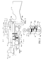
- Figure 1 is a simplified side elevational view of the firearm portion of the fire control system of an embodiment of the present invention.
- Figure 2 is a front elevational view taken along the line 2-2 of Figure 1.
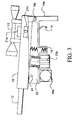
- Figure 3 is a side elevation view similar to Figure 1 showing a barrel tilted vertically.
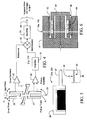
- FIG. 4 is a rate sensor utilized in an embodiment of the present invention simplified and shown partially in block diagram.
- Figure 5 is a simplified plan view and a simplified circuit showing a position sensor used in an embodiment of the present invention.
- Figure 6 is a cross sectional view of an actuator used in an embodiment of the present invention.
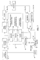
- Figure 7 is an overall block diagram of the fire control system of an embodiment of the present invention.
- Figure 8 is a detailed side view of trigger mechanism shown schematically in Figure 7.
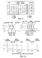
- Figure 9 is a table illustrating fuzzy logic rules.
- Figure 10, 11 and 12 are graphical membership functions illustrating the implementation of the fuzzy logic of an embodiment of the present invention.
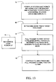
- Figure 13 is a flow sheet illustrating the method of an embodiment of the invention.
- Figures 1 and 2 show respectively a side view and a front view of a stabilized rifle constructed and controlled in accordance with the fire control system of an embodiment of the present invention.
- the rifle has a stock 11 which is held and movable by a human being who fires the rifle, a barrel 12, a gun sight or scope 13 mounted and movable with barrel 12 (necessarily so since the sight 13 must be lined up with the bore sight of the barrel 12), and a trigger unit 14.
- barreled action 15 is illustrated which is in the form of a U-shaped channel which carries within it barrel 12 and the remainder of the loading and firing apparatus and, of course, it carries the scope 13 as well as motion sensors 21a and 21b which will be described below.
- This entire barreled action 15 is mounted for vertical movement within the rigid vertical channel shaped support 62 which actually is a part of the horizontal pivot assembly.
- Support 62 has at its end a horizontal pivot assembly 16a which pivots in the stock 11 by a cylindrical vertically mounted bearing.
- the horizontal pivot assembly 16a allows a horizontal movement of support 62 over a small angle.
- the support does not allow the barreled action 15 to move horizontally within it but allows free movement of the barreled action vertically on a horizontally mounted bearing 16b which is mounted on the same axis (but perpendicular to that axis) as the horizontal bearing assembly 16a.
- the pivot 16b allows the barreled action 15 including barrel 12 to move over a predetermined angle, typically + or - 1.5° in the elevation direction, as illustrated in Figure 3.
- a predetermined angle typically + or - 1.5° in the elevation direction
- the showing in Figure 3 is greatly exaggerated. The same is true of the horizontal motion of the support 61 and its pivot 16a.
- the springs 61 mounted between the vertical channel support 62 and to the stock 11 nominally center the barrel horizontally in a monostable position substantially aligned with the stock absent any external forces.
- the spring 19 does the same thing with respect to barreled action 15 in the vertical direction.
- the barreled action 15 and the barrel 12 are freely movable (except for the slight resistance of the springs) over azimuth and elevation directions of predetermined angles.
- actuators 18a and 18b are provided horizontal and vertical actuators (or rather azimuth and elevation actuators) 18a and 18b.
- Actuator 18a is best shown in Figure 2 and has a portion attached to stock 11 with a movable portion attached to vertical channel support 62.
- the vertical channel support is actually part of the horizontal pivot assembly.
- a vertical actuator 18b (best shown in Figure 1) has a fixed portion connected to stock 11 and a movable portion to barreled action 15 as shown in Figure 3.
- These actuators are actually voice coil type actuators as fully illustrated in Figure 6 which is a cross-sectional view.
- Each includes the soft iron base 41, a permanent magnet 42, a tubular coil 44 in a movable holder, and a fixed working air-gap 46.
- the permanent magnet field and coil winding produce a force proportional to the current applied to the coil.
- This actuator is commercially available from Kimco Magnetics Division of the assignee of the present application located in San Marcos, California.
- a pair of position sensors 22a and 22b which are actually mounted within the respective actuators 18a and 18b. They are, in effect, a potentiometer system which senses any deviation from a nominal center point. In other words, output signals are provided related to movement of the barrel in azimuth and elevation directions with respect to stock.
- the two portions of each position sensor are respectively mounted to the fixed and movable portions of their associated position sensor as illustrated in Figures 1 and 2.
- These position sensors 22a and 22b are commercially available, as fully illustrated in Figure 5, and are termed linear position sensors.
- a potentiometer unit 39 which provides the position sensing output signal at 40.
- the shaft 37 is spring loaded to automatically return to an extended position.
- This unit is available as Model No. 9600 Series from the Duncan Electronics Division, a subsidiary of the assignee of the present invention, and located in Tustin, California.
- motion or rate sensors 21a and 21b mounted on barreled action 15. As will be discussed below they are actuated by a first detent in trigger 14 which occurs just before the trigger is about to be actuated to fire the rifle; the time lapse may be a split second or several seconds depending on how the target is being tracked by the human being firing the rifle. This period of time between actuation of rate sensors 21a and 21b and the firing is termed the stabilized mode.
- the tracking mode is initiated, as will be discussed below, by turning the on-off switch 24 ( Figure 1) mounted on the stock 11 to the on position to actuate the electronics 23.
- These electronics as will be discussed below are part of the servomechanism system and fuzzy logic controller of an embodiment of the present invention.
- Each rate sensor 21a and 21b generates in response to movement in the horizontal or vertical direction respectively, a signal only with rotation around the axis of symmetry designated 25 (see rate sensor 21b). Therefore as illustrated in Figure 1 the rate sensor 21a would have its axis mounted in a different direction than rate sensor 21b. Thus the rate sensor senses the movement only in the plane that its output signal will control.
- the rate sensor When the rate sensor senses rotational movement in that plane, it produces an output signal proportional to that rate of movement to the electronic controller or servomechanism 23.
- the electronics then processes the signal voltage to apply a countering voltage to the respective linear actuators 18a and 18b. This closed loop will be discussed in detail below and how the fuzzy logic control system works to maintain the rate sensor output as zero. This eliminates movement of stock 11 from being transmitted to barreled action 15 except for that which is transmitted through the springs which is a very smooth movement by comparison.
- FIG 4 illustrates the details of the miniaturized solid state rate sensors 21a and 21b which use a pair of quartz vibrating tuning forks, with the drive tines 26 and the pickup tines 27, to sense angular velocity or rate.
- a rotational motion about the sensors longitudinal axis 25 produces a DC voltage as shown at output 28 proportional to the rotation rate of the sensors.
- the microminiature double ended quartz tuning forks 26, 27, and supporting structure are fabricated chemically from a single wafer of monocrystalline isolectric quartz.
- Associated processing circuitry includes a drive oscillator 29, a pickup amplifier 30 and supplementary amplifier 31 which are all fed to a demodulator 32 and amplified at 33.
- the two position sensors 22a and 22b cause the barrel to be virtually motionless within the stock while the stock is moved around to track the target.
- the output signal of these position sensors after processing by the fuzzy logic controller to be described below, causes the actuators 18a, 18b to maintain or lock the barrel in alignment with the stock (with respect to azimuth and elevation). From a common sense point of view this allows the person firing the rifle to effectively use the sight 13 to acquire or track the target (sight the target).
- the system enters a stabilized mode where the rate sensors 22a and 22b drive the actuators to actually move the barrel with reference to the stock (making the barrel immune to movement of the stock) to facilitate remaining sighted on the tracked target irrespective of movement of the stock.
- Figure 7 is a block diagram of the servomechanism or fire control system for the rifle stock and barrel, 11 and 17.
- a separate logic system would be used for azimuth and elevation directions of the system.
- the fuzzy logic controller unit is shown at 54 which detects the outputs on line 56 of the rate and position sensors 21a, 21b and 22a, 22b in the appropriate time sequence (first during the tracking mode for the position sensors and then during the stabilized mode for the rate sensors). Then by means of the three well known functional steps of a fuzzy logic controller, the output signals from the sensors are converted to drive signals for the actuators 18a and 18b.
- the rate of change of these signals is computed in a sensor rate of change unit 60 which measures the sensor output in equal time intervals (approximately 800 microseconds) and computes the difference between the two subsequent readings.
- the change from a tracking mode where the position sensor is connected to the fuzzy controller 54 via line 56 and the stabilized mode where the rate sensor is connected is accomplished by a switch 66 which is driven through an amplifier 67 by the rifle trigger 14 being moved to a first detent position at 68. And then as shown by the dashed line 69, the final position is the firing position. Of course, electrical contact is still made with amplifier 67. To initiate the tracking mode and activate the electronics on-off switch 24 (which is on the stock of the rifle) is turned on.
- Figure 8 more aptly illustrates the foregoing action of the trigger 14 where the trigger includes a lever portion 70 which normally abuts in its rest position as illustrated in Figure 8 against a leaf spring contact 71. However when rotated to its first detent position, where the servomechanism system is placed in the stabilizing mode, lever 70 moves lower spring contact 71 against upper contact 72 to close a pair of electrical contacts designated as 68'; this is, in essence, the contact 68 illustrated in Figure 7. Amplifier 67 is actuated causing switch 66 to switch the position sensor to the rate sensor as illustrated in Figure 7.
- Solenoid 75 is grounded which actuates the sear of the firing mechanism (since this is so well known this is not shown). Solenoid 75 is powered by a charged up capacitor 76 which is charged through resistor 77 by a 12-volt battery 78 which is continuously connected to the capacitor. Closure of contact 69' connects solenoid 75 to ground, thus producing a one shot firing action.
- the capacitor 76 requires three to four seconds to recharge or reset. Thus the circuit is an effective resetable one shot logic circuit. This conforms to the physical operation of the rifle and its trigger since a person firing the rifle would continue to squeeze the trigger. The amount of current flowing in the capacitor 76 is limited by the resistor 77 so as not to discharge the battery 78
- Both trigger 14 and the electrical trigger switching means constituting the contacts 71, 72, 74, 76 are all fixed or attached to stock 11.
- the barrel 15 is still freely movable being attached to the trigger mechanism by only a pair of thin wires which connect to the solenoid 75 which, of course, is carried by the movable barrel and the necessary components of the sear mechanism to cause firing. Since. the trigger is physically isolated from movement of barrel 15 any unwanted restrictive mechanical feedback by the firing person during actuation of the trigger is prevented.
- the fuzzy controller for the rifle stabilization system receives error information (rifle motion) from the rate and position sensors in each of two axes (azimuth and elevation) and using the principles of fuzzy logic drives the actuators in azimuth and elevation directions to eliminate motion induced error.
- error information rifle motion
- the barrel since it is bearing mounted it is necessarily fairly freely moveable, to insure accurate tracking the barrel is maintained in its monostable aligned position by the actuators.
- the same fuzzy logic system upon the activation of the trigger to a first detent activates the rate sensor output to be used for controlling the actuators which move the barrel (within the + - 1.5° limitation) to compensate for motion induced error either by the wobble of the gunner or the motion of the platform.
- the shift between the tracking and firing modes is ideally done almost instantaneously and thus electronically.
- Use of the same fuzzy logic controller makes this possible. However a simple solution if feasible, might be a mechanical lock that would be withdrawn by moving the trigger to the first detent.
- fuzzy logic controller is superior to other control systems such as a proportional derivative (PID system) where because the stabilization system must center on a dead zone, a PID system is subject to vibration. It is also believed such a PID system could not easily shift between the tracking and firing modes. But the fuzzy logic aptly lends itself to such common use.
- PID system proportional derivative
- the fuzzy logic controller 54 illustrated in Figure 7, is governed by the seven rules of Figure 9.
- the "output signal” is, of course, a signal from either the rate or position sensors 21a, 21b and 22a, 22b. Depending on the magnitude of the signal, it could indicate the barrel has moved or should be moved to the left, right, or far left or far right, or centered at zero aligned with the stock.
- the other input is "Rate of Change” (see unit 60) which is negative, positive or zero.
- the intuitive result of these two inputs is an output to the azimuth or elevation actuators 18a, 18b, of large or small positive or negative movements, or normal positive or negative movements or zero.
- the following example shows how to derive a crisp value.
- the "crisp" value of the SENSOR OUTPUT (see Figure 11) is 2.54 Vdc (which is equal to a count of 127 when digitized by an 8-bit analog-to-digital converter with a 5 Vdc as reference)
- ZERO has a degree of membership of .65
- RIGHT has a degree of membership of .35.
- the "crisp" value of SENSOR RATE is equal to +1
- ZERO has a degree of membership of .75
- POSITIVE has a degree of membership of .25.
- rules 4 and 6 are both active.
- step 78 states that the system electronics are powered up including position sensors and actuators to effectively lock the barrel to the stock. And the powering up is done, of course, by activating the on-off switch 24. This could alternatively be done by another detent location on the rifle trigger. And alternatively, rather than powering up the electronics at this point, as indicated by an alternative step 79, no power up is necessary until it is desired to activate the rate sensors 21a, 21b. However in a preferred embodiment, power up occurs to activate the position sensors and actuators to effectively lock the barrel to the stock. And then in step 80 the user of the rifle or gun tracks the target through the sight.
- step 81 when the target is sighted the trigger is pulled to the first detent to release the barrel for azimuth and elevation movement. Thus the effective lock is released between the barrel and the stock.
- the rate sensors are also activated to place the system in a stabilized mode where the output signals from the rate sensors drive the actuators to make the barrel relatively immune to movement of the stock.
- step 82 when the rifle continues to be aimed, the trigger is pulled to the final position to fire the rifle.
- embodiments of the present invention provide a unique battery operated stabilization system, especially for direct fire weapons such as sniper rifles, and small arms fired from moving platforms such as helicopters and fast attack vehicles.
- the use of micro machined inertial rate sensors, position sensors, and actuators together with a fuzzy inference engine results in a highly effective low cost control system that has applications in many other fields.
Applications Claiming Priority (2)
| Application Number | Priority Date | Filing Date | Title |
|---|---|---|---|
| US08/908,023 US5974940A (en) | 1997-08-20 | 1997-08-20 | Rifle stabilization system for erratic hand and mobile platform motion |
| US908023 | 1997-08-20 |
Publications (3)
| Publication Number | Publication Date |
|---|---|
| EP0898144A2 true EP0898144A2 (fr) | 1999-02-24 |
| EP0898144A3 EP0898144A3 (fr) | 2000-09-06 |
| EP0898144B1 EP0898144B1 (fr) | 2005-11-16 |
Family
ID=25425022
Family Applications (1)
| Application Number | Title | Priority Date | Filing Date |
|---|---|---|---|
| EP98305942A Expired - Lifetime EP0898144B1 (fr) | 1997-08-20 | 1998-07-27 | Mécanisme de stabilisation pour un fusil qui est tiré à partir d'un main instable ou d'une plate-forme en mouvement |
Country Status (4)
| Country | Link |
|---|---|
| US (1) | US5974940A (fr) |
| EP (1) | EP0898144B1 (fr) |
| JP (1) | JP3096275B2 (fr) |
| DE (1) | DE69832339T2 (fr) |
Cited By (7)
| Publication number | Priority date | Publication date | Assignee | Title |
|---|---|---|---|---|
| WO2000079207A1 (fr) * | 1999-06-21 | 2000-12-28 | Ae Angerer Enterprises Gmbh | Dispositif de visee pour une arme avec detection d'image et evaluation pour compensation de mouvements non intentionnels pendant le processus de visee |
| WO2010053436A1 (fr) * | 2008-11-04 | 2010-05-14 | Tommy Andersson | Procédé et dispositif de stabilisation d’une direction de visée pour des armes à feu et arme à feu |
| CN102853718A (zh) * | 2011-06-28 | 2013-01-02 | 叶晓斌 | 圆弧面一体化甲型自动步枪 |
| CN102853720A (zh) * | 2011-06-28 | 2013-01-02 | 叶晓斌 | 圆弧面一体化乙型自动步枪 |
| US9110295B2 (en) | 2010-02-16 | 2015-08-18 | Trackingpoint, Inc. | System and method of controlling discharge of a firearm |
| US9612088B2 (en) | 2014-05-06 | 2017-04-04 | Raytheon Company | Shooting system with aim assist |
| US10782097B2 (en) | 2012-04-11 | 2020-09-22 | Christopher J. Hall | Automated fire control device |
Families Citing this family (45)
| Publication number | Priority date | Publication date | Assignee | Title |
|---|---|---|---|---|
| US7579269B2 (en) * | 1993-11-16 | 2009-08-25 | Formfactor, Inc. | Microelectronic spring contact elements |
| US7856750B2 (en) * | 1997-12-08 | 2010-12-28 | Horus Vision Llc | Apparatus and method for calculating aiming point information |
| GB9916676D0 (en) * | 1999-07-15 | 1999-09-15 | Scient Generics Ltd | Effiecient optical source for weapon sights |
| US6604064B1 (en) * | 1999-11-29 | 2003-08-05 | The United States Of America As Represented By The Secretary Of The Navy | Moving weapons platform simulation system and training method |
| CZ20004598A3 (cs) * | 2000-12-08 | 2002-06-12 | Marcel Ing. Mgr. Jiřina Ph.D. | Zaměřovač, zejména pro ruční zbraně |
| US9310165B2 (en) | 2002-05-18 | 2016-04-12 | John Curtis Bell | Projectile sighting and launching control system |
| US6886287B1 (en) | 2002-05-18 | 2005-05-03 | John Curtis Bell | Scope adjustment method and apparatus |
| US8468930B1 (en) | 2002-05-18 | 2013-06-25 | John Curtis Bell | Scope adjustment method and apparatus |
| US7624528B1 (en) | 2002-05-18 | 2009-12-01 | John Curtis Bell | Scope adjustment method and apparatus |
| US7549367B2 (en) * | 2004-01-20 | 2009-06-23 | Utah State University Research Foundation | Control system for a weapon mount |
| US8375620B2 (en) * | 2004-03-10 | 2013-02-19 | Raytheon Company | Weapon sight having multi-munitions ballistics computer |
| US7490430B2 (en) | 2004-03-10 | 2009-02-17 | Raytheon Company | Device with multiple sights for respective different munitions |
| US7171776B2 (en) * | 2004-03-10 | 2007-02-06 | Raytheon Company | Weapon sight having analog on-target indicators |
| US7269920B2 (en) * | 2004-03-10 | 2007-09-18 | Raytheon Company | Weapon sight with ballistics information persistence |
| US20050241207A1 (en) * | 2004-03-10 | 2005-11-03 | Raytheon Company, A Corporation Of The State Of Delaware | Common aperture time-division-multiplexed laser rangefinder |
| US7563097B2 (en) * | 2004-09-03 | 2009-07-21 | Techno-Sciences, Inc. | Stabilizing hand grip system |
| US8074394B2 (en) * | 2005-03-08 | 2011-12-13 | Lowrey Iii John William | Riflescope with image stabilization |
| CN100489702C (zh) * | 2005-07-07 | 2009-05-20 | 上海交通大学 | 基于模糊自适应算法的船舶动力定位控制系统 |
| US7743543B2 (en) | 2005-10-06 | 2010-06-29 | Theodore Karagias | Trigger mechanism and a firearm containing the same |
| DE102007005939A1 (de) * | 2007-02-01 | 2008-08-07 | Oerlikon Contraves Ag | Tragbare Mehrzweckwaffe |
| US8011130B2 (en) * | 2007-07-06 | 2011-09-06 | Raytheon Company | Gun sight mounting device |
| US20090217565A1 (en) * | 2008-01-11 | 2009-09-03 | Ford Timothy D F | Splatter indicator sight for firearms |
| WO2010132831A1 (fr) | 2009-05-15 | 2010-11-18 | Dennis Sammut | Appareil et procédé pour calculer des informations de point de visée |
| DE102009031620A1 (de) | 2009-07-03 | 2011-02-24 | Carl Zeiss Optronics Gmbh | Waffenbaugruppe, Waffensystem, sowie Verfahren für eine Waffenbaugruppe und Verfahren für ein Waffensystem |
| US8453368B2 (en) * | 2010-08-20 | 2013-06-04 | Rocky Mountain Scientific Laboratory, Llc | Active stabilization targeting correction for handheld firearms |
| US8245623B2 (en) * | 2010-12-07 | 2012-08-21 | Bae Systems Controls Inc. | Weapons system and targeting method |
| WO2013106280A1 (fr) | 2012-01-10 | 2013-07-18 | Horus Vision Llc | Appareil et procédé permettant de calculer des informations de point de visée |
| US9036035B2 (en) | 2012-04-30 | 2015-05-19 | Trackingpoint, Inc. | Rifle scope with video output stabilized relative to a target |
| US8863427B2 (en) * | 2012-11-21 | 2014-10-21 | Grip Plus Inc | Automatically adjustable comb for a firearm |
| WO2014110262A2 (fr) | 2013-01-11 | 2014-07-17 | Dennis Sammut | Appareil et procédé pour calculer une information de point de visée |
| DE102013006939A1 (de) | 2013-04-23 | 2014-10-23 | Rheinmetall Waffe Munition Gmbh | Adaptive Beschleunigungsbegrenzung |
| US9222754B2 (en) * | 2013-06-07 | 2015-12-29 | Trackingpoint, Inc. | Precision guided firearm with hybrid sensor fire control |
| US9377255B2 (en) | 2014-02-03 | 2016-06-28 | Theodore Karagias | Multi-caliber firearms, bolt mechanisms, bolt lugs, and methods of using the same |
| RU2549215C1 (ru) * | 2014-02-06 | 2015-04-20 | Открытое акционерное общество "Военно-промышленная корпорация "Научно-производственное объединение машиностроения" | Способ прицеливания крылатых ракет, базирующихся на самоходной пусковой установке |
| KR101932544B1 (ko) * | 2014-04-16 | 2018-12-27 | 한화지상방산 주식회사 | 원격무장 장치 및 제어방법 |
| US9784529B1 (en) * | 2015-04-07 | 2017-10-10 | Matthew G. Angle | Small arms stabilization system |
| GB201700648D0 (en) * | 2017-01-13 | 2017-03-01 | Marksmanship Tech Ltd | System and method for correcting aim by motion analysis for small arms weapons |
| AU2018423158A1 (en) * | 2017-11-03 | 2020-05-21 | Aimlock Inc. | Semi-autonomous motorized weapon systems |
| AU2019388605A1 (en) | 2018-09-04 | 2021-02-18 | Hvrt Corp. | Reticles, methods of use and manufacture |
| US11067347B2 (en) | 2018-11-30 | 2021-07-20 | Theodore Karagias | Firearm bolt assembly with a pivoting handle |
| US20220163282A1 (en) * | 2019-04-10 | 2022-05-26 | Majr Mechatronics Llc | Stabilization device |
| US11211837B2 (en) | 2019-06-25 | 2021-12-28 | General Dynamics Land Systems—Canada | Actuator with individually computerized and networked electromagnetic poles |
| WO2021080683A1 (fr) | 2019-10-25 | 2021-04-29 | Aimlock Inc. | Détente et dispositif d'actionnement de sécurité et procédé associé |
| US11274904B2 (en) | 2019-10-25 | 2022-03-15 | Aimlock Inc. | Remotely operable weapon mount |
| EP4343265A1 (fr) * | 2022-07-17 | 2024-03-27 | Osamu Kubota | Fusil et mécanisme de gâchette |
Citations (1)
| Publication number | Priority date | Publication date | Assignee | Title |
|---|---|---|---|---|
| US4524619A (en) | 1984-01-23 | 1985-06-25 | Piezoelectric Technology Investors, Limited | Vibratory angular rate sensor system |
Family Cites Families (10)
| Publication number | Priority date | Publication date | Assignee | Title |
|---|---|---|---|---|
| CH112628A (de) * | 1923-10-25 | 1925-11-02 | Dansk Rekylriffel Syndikat As | Höhenrichtungsvorrichtung für Maschinengewehre. |
| US2069750A (en) * | 1935-11-25 | 1937-02-09 | Charles H Coates | Apparatus for training in gunfire |
| FR2231934A1 (en) * | 1973-05-29 | 1974-12-27 | Tellie Paul | Light automatic firearm - intermediate sleeve around barrel at breech end gives cooling space |
| DE3643197A1 (de) * | 1986-12-18 | 1988-06-23 | Messerschmitt Boelkow Blohm | Zieleinrichtung eines waffenrohres |
| US4999939A (en) * | 1987-12-31 | 1991-03-19 | Springfield Armory, Inc. | Breech load pistol and conversion |
| DE3930565C1 (en) * | 1989-09-13 | 1990-09-06 | Messerschmitt-Boelkow-Blohm Gmbh, 8012 Ottobrunn, De | Flexible support for aircraft or tank gun - uses rubber rings inside support tube allowing swivelling for aiming |
| DE3930567C1 (en) * | 1989-09-13 | 1990-09-06 | Messerschmitt-Boelkow-Blohm Gmbh, 8012 Ottobrunn, De | Gun on aircraft or tank - has flexible supports for barrel inside outer tube |
| FR2691792A1 (fr) * | 1992-06-02 | 1993-12-03 | Giat Ind Sa | Dispositif de déclenchement du tir d'une arme à feu. |
| US5456157A (en) * | 1992-12-02 | 1995-10-10 | Computing Devices Canada Ltd. | Weapon aiming system |
| FR2737001B1 (fr) * | 1995-07-20 | 1997-08-29 | Giat Ind Sa | Dispositif de stabilisation pour arme a feu individuelle |
-
1997
- 1997-08-20 US US08/908,023 patent/US5974940A/en not_active Expired - Fee Related
-
1998
- 1998-07-27 DE DE69832339T patent/DE69832339T2/de not_active Expired - Fee Related
- 1998-07-27 EP EP98305942A patent/EP0898144B1/fr not_active Expired - Lifetime
- 1998-08-12 JP JP10228176A patent/JP3096275B2/ja not_active Expired - Fee Related
Patent Citations (1)
| Publication number | Priority date | Publication date | Assignee | Title |
|---|---|---|---|---|
| US4524619A (en) | 1984-01-23 | 1985-06-25 | Piezoelectric Technology Investors, Limited | Vibratory angular rate sensor system |
Cited By (12)
| Publication number | Priority date | Publication date | Assignee | Title |
|---|---|---|---|---|
| WO2000079207A1 (fr) * | 1999-06-21 | 2000-12-28 | Ae Angerer Enterprises Gmbh | Dispositif de visee pour une arme avec detection d'image et evaluation pour compensation de mouvements non intentionnels pendant le processus de visee |
| WO2010053436A1 (fr) * | 2008-11-04 | 2010-05-14 | Tommy Andersson | Procédé et dispositif de stabilisation d’une direction de visée pour des armes à feu et arme à feu |
| US8601736B2 (en) | 2008-11-04 | 2013-12-10 | Tommy Andersson | Method and a device for stabilizing aiming direction for rifles and handguns and fire arm |
| US9110295B2 (en) | 2010-02-16 | 2015-08-18 | Trackingpoint, Inc. | System and method of controlling discharge of a firearm |
| US9823047B2 (en) | 2010-02-16 | 2017-11-21 | Trackingpoint, Inc. | System and method of controlling discharge of a firearm |
| CN102853718A (zh) * | 2011-06-28 | 2013-01-02 | 叶晓斌 | 圆弧面一体化甲型自动步枪 |
| CN102853720A (zh) * | 2011-06-28 | 2013-01-02 | 叶晓斌 | 圆弧面一体化乙型自动步枪 |
| CN102853718B (zh) * | 2011-06-28 | 2016-01-27 | 叶晓斌 | 圆弧面覆盖整体结构固定一体化自动步枪结构 |
| CN102853720B (zh) * | 2011-06-28 | 2016-02-17 | 叶晓斌 | 圆弧面覆盖整体结构固定一体化自动步枪结构 |
| US10782097B2 (en) | 2012-04-11 | 2020-09-22 | Christopher J. Hall | Automated fire control device |
| US11619469B2 (en) | 2013-04-11 | 2023-04-04 | Christopher J. Hall | Automated fire control device |
| US9612088B2 (en) | 2014-05-06 | 2017-04-04 | Raytheon Company | Shooting system with aim assist |
Also Published As
| Publication number | Publication date |
|---|---|
| EP0898144B1 (fr) | 2005-11-16 |
| EP0898144A3 (fr) | 2000-09-06 |
| US5974940A (en) | 1999-11-02 |
| JP3096275B2 (ja) | 2000-10-10 |
| JPH11118394A (ja) | 1999-04-30 |
| DE69832339T2 (de) | 2006-07-27 |
| DE69832339D1 (de) | 2005-12-22 |
Similar Documents
| Publication | Publication Date | Title |
|---|---|---|
| EP0898144B1 (fr) | Mécanisme de stabilisation pour un fusil qui est tiré à partir d'un main instable ou d'une plate-forme en mouvement | |
| US7533849B2 (en) | Optically guided munition | |
| US9310165B2 (en) | Projectile sighting and launching control system | |
| US7834300B2 (en) | Ballistic guidance control for munitions | |
| US8450668B2 (en) | Optically guided munition control system and method | |
| US9823047B2 (en) | System and method of controlling discharge of a firearm | |
| EP1514070B1 (fr) | Module de telecommande pour vehicule | |
| US7703719B1 (en) | Scope adjustment method and apparatus | |
| US7624528B1 (en) | Scope adjustment method and apparatus | |
| US20130298438A1 (en) | Method of Movement Compensation for a Weapon | |
| US7690291B2 (en) | Dual elevation weapon station and method of use | |
| US9784529B1 (en) | Small arms stabilization system | |
| US5966859A (en) | Devices and methods for controlled manual and automatic firearm operation | |
| EP0785406A2 (fr) | Procédé et dispositif de conduite de tir d'une arme à trajectoire à haute apogée | |
| US20120037702A1 (en) | Apparatus and method for synthetic weapon stabilization and firing | |
| AU2019272045B2 (en) | Firearm controlled by user behavior | |
| US5834677A (en) | Stabilizing device for a small fire arm | |
| IL303515A (en) | A two-mode fire control system is mounted on the weapon | |
| US20240027158A1 (en) | Firearm firing control assembly and firearm optic positioning assembly | |
| US20240027159A1 (en) | Firearm firing control system and red dot positioning assembly | |
| EP4025498A1 (fr) | Véhicule aérien sans pilote armé et des procédés d'utilisation associés | |
| KR102318621B1 (ko) | 차량 탑재형 원격무장시스템에 대한 자세 제어방법 및 자세 제어시스템 | |
| JP2522833B2 (ja) | 飛翔体の発射装置 | |
| RU2162587C1 (ru) | Способ формирования команды на разрешение выстрела по величине зоны разрешения выстрела и устройство для его осуществления | |
| Von Wahlde et al. | Application of an Inertial Reticle System to an Objective Personal Weapon |
Legal Events
| Date | Code | Title | Description |
|---|---|---|---|
| PUAI | Public reference made under article 153(3) epc to a published international application that has entered the european phase |
Free format text: ORIGINAL CODE: 0009012 |
|
| AK | Designated contracting states |
Kind code of ref document: A2 Designated state(s): DE FR GB |
|
| AX | Request for extension of the european patent |
Free format text: AL;LT;LV;MK;RO;SI |
|
| PUAL | Search report despatched |
Free format text: ORIGINAL CODE: 0009013 |
|
| AK | Designated contracting states |
Kind code of ref document: A3 Designated state(s): AT BE CH CY DE DK ES FI FR GB GR IE IT LI LU MC NL PT SE |
|
| AX | Request for extension of the european patent |
Free format text: AL;LT;LV;MK;RO;SI |
|
| RIC1 | Information provided on ipc code assigned before grant |
Free format text: 7F 41A 21/48 A, 7F 41A 27/30 B, 7F 41G 3/00 B, 7F 41A 19/58 B, 7F 41A 27/28 B |
|
| 17P | Request for examination filed |
Effective date: 20010124 |
|
| AKX | Designation fees paid |
Free format text: DE FR GB |
|
| 17Q | First examination report despatched |
Effective date: 20021018 |
|
| GRAP | Despatch of communication of intention to grant a patent |
Free format text: ORIGINAL CODE: EPIDOSNIGR1 |
|
| GRAS | Grant fee paid |
Free format text: ORIGINAL CODE: EPIDOSNIGR3 |
|
| GRAA | (expected) grant |
Free format text: ORIGINAL CODE: 0009210 |
|
| AK | Designated contracting states |
Kind code of ref document: B1 Designated state(s): DE FR GB |
|
| REG | Reference to a national code |
Ref country code: GB Ref legal event code: FG4D |
|
| REF | Corresponds to: |
Ref document number: 69832339 Country of ref document: DE Date of ref document: 20051222 Kind code of ref document: P |
|
| ET | Fr: translation filed | ||
| PG25 | Lapsed in a contracting state [announced via postgrant information from national office to epo] |
Ref country code: GB Free format text: LAPSE BECAUSE OF NON-PAYMENT OF DUE FEES Effective date: 20060727 |
|
| PLBE | No opposition filed within time limit |
Free format text: ORIGINAL CODE: 0009261 |
|
| STAA | Information on the status of an ep patent application or granted ep patent |
Free format text: STATUS: NO OPPOSITION FILED WITHIN TIME LIMIT |
|
| 26N | No opposition filed |
Effective date: 20060817 |
|
| PG25 | Lapsed in a contracting state [announced via postgrant information from national office to epo] |
Ref country code: DE Free format text: LAPSE BECAUSE OF NON-PAYMENT OF DUE FEES Effective date: 20070201 |
|
| GBPC | Gb: european patent ceased through non-payment of renewal fee |
Effective date: 20060727 |
|
| REG | Reference to a national code |
Ref country code: FR Ref legal event code: ST Effective date: 20070330 |
|
| PG25 | Lapsed in a contracting state [announced via postgrant information from national office to epo] |
Ref country code: FR Free format text: LAPSE BECAUSE OF NON-PAYMENT OF DUE FEES Effective date: 20060731 |