EP0897782A2 - Lathe charger - Google Patents
Lathe charger Download PDFInfo
- Publication number
- EP0897782A2 EP0897782A2 EP98115446A EP98115446A EP0897782A2 EP 0897782 A2 EP0897782 A2 EP 0897782A2 EP 98115446 A EP98115446 A EP 98115446A EP 98115446 A EP98115446 A EP 98115446A EP 0897782 A2 EP0897782 A2 EP 0897782A2
- Authority
- EP
- European Patent Office
- Prior art keywords
- centering
- holding arms
- raw wood
- spindles
- holding
- Prior art date
- Legal status (The legal status is an assumption and is not a legal conclusion. Google has not performed a legal analysis and makes no representation as to the accuracy of the status listed.)
- Granted
Links
Images


Classifications
-
- B—PERFORMING OPERATIONS; TRANSPORTING
- B27—WORKING OR PRESERVING WOOD OR SIMILAR MATERIAL; NAILING OR STAPLING MACHINES IN GENERAL
- B27L—REMOVING BARK OR VESTIGES OF BRANCHES; SPLITTING WOOD; MANUFACTURE OF VENEER, WOODEN STICKS, WOOD SHAVINGS, WOOD FIBRES OR WOOD POWDER
- B27L5/00—Manufacture of veneer ; Preparatory processing therefor
- B27L5/02—Cutting strips from a rotating trunk or piece; Veneer lathes
- B27L5/022—Devices for determining the axis of a trunk ; Loading devices for veneer lathes
-
- Y—GENERAL TAGGING OF NEW TECHNOLOGICAL DEVELOPMENTS; GENERAL TAGGING OF CROSS-SECTIONAL TECHNOLOGIES SPANNING OVER SEVERAL SECTIONS OF THE IPC; TECHNICAL SUBJECTS COVERED BY FORMER USPC CROSS-REFERENCE ART COLLECTIONS [XRACs] AND DIGESTS
- Y10—TECHNICAL SUBJECTS COVERED BY FORMER USPC
- Y10T—TECHNICAL SUBJECTS COVERED BY FORMER US CLASSIFICATION
- Y10T82/00—Turning
- Y10T82/25—Lathe
- Y10T82/2514—Lathe with work feeder or remover
Landscapes
- Engineering & Computer Science (AREA)
- Life Sciences & Earth Sciences (AREA)
- Manufacturing & Machinery (AREA)
- Wood Science & Technology (AREA)
- Forests & Forestry (AREA)
- Manufacture Of Wood Veneers (AREA)
- Jigs For Machine Tools (AREA)
- Turning (AREA)
- Replacement Of Web Rolls (AREA)
Abstract
Description
- The present invention relates to an apparatus, that is, a lathe charger, for automatically supplying raw wood to a veneer lathe such that the cutting center of the raw wood is determined so that the cutting center of the raw wood and the axis of a spindle of the veneer lathe coincide with each other.
- Hitherto, a method and an apparatus for centering raw wood have been disclosed in Japanese Patent Publication No. 4-60001. The method of centering raw wood comprises the steps of: rotating raw wood about a temporary center by a holding claw disposed at a limit of rearward movement of the raw wood to wait for raw wood; detecting the profiles of cross sections of a plurality of portions in the lengthwise direction of the raw wood so that the coordinates of the axis of the overall body of the raw wood are obtained; forwards moving the holding claw in accordance with the coordinates so that the position of the raw wood in the direction of the X axis is corrected; downwards moving a conveying claw so that the position of the raw wood in the direction of the Y axis is corrected; and changing the claw for holding the raw wood from the holding claw to the conveying claw. The apparatus for centering raw wood comprises: an X-axis correction unit which permits a pair of bearing boxes to move horizontally between frames which are stood erect; spindles each having a holding claw at an end thereof and a rotational-angle sensor and slidably inserted into the pair of the bearing boxes; a mobile unit made to be movable such that the mobile unit is guided by a horizontal beam; conveying claws permitted to be moved upwards/downwards by a Y-axis correction unit and suspended from two sides of the mobile unit: and a displacement-amount sensor provided for the base end of each of a plurality of swingable arms disposed at arbitrary intervals in a lengthwise direction of the raw wood and connected by a pin, wherein an output of an amount of correction of the forward movement of the bearing box is produced to the X-axis correction unit and an output of an amount of correction of the downward movement of the conveying claw is produced to the Y-axis correction unit in accordance with the coordinates of the total axis obtained from data of each of the rotational-angle sensor and the displacement-amount sensor.
- The above-mentioned conventional technology, however, suffers from the following problem: the X-axis correction unit must have the structure that both of the pair of the bearing boxes are made to be movable individually in the horizontal direction. Therefore, the manufacturing cost of the apparatus cannot be reduced and the structure becomes too complicated.
- Accordingly, an object of the present invention is to provide a lathe charger which is capable of correcting positions in the directions of X and Y axes with a simple structure and having an automated centering process using a centering spindle and holding and conveying processes using a holding arm.
- To achieve the above-mentioned object, according to one aspect of the present invention, there is provided a lathe charger comprising: a pair of centering spindles for holding end surfaces of raw wood; centering means for automatically calculating cutting centers of the two end surfaces of the raw wood held by the pair of the centering spindles; a pair of holding arms for holding the raw wood in place of the pair of the spindles; and means for moving the holding arms in such a manner as to move the pair of holding arms between the centering spindles and spindles of a veneer lathe for an arbitrary distance, wherein the pair of the holding arms can be extended/contracted and one of the pair of the centering spindles is structured to be capable of moving in a direction which intersects a direction in which the pair of the holding arms are extended/contracted, and a control mechanism is provided with which when one of the end surfaces is viewed in parallel with the axis of the centering spindles in a state in which the raw wood having cutting centers of the two end surfaces which have been calculated is held, one of the centering spindles structured to be capable of moving is moved until an imaginary straight line passing through the two coincident cutting centers is made to be in parallel with the direction in which the holding arms are extended/contracted at the position at which the holding arms hold the raw wood, members for holding the raw wood are changed from the centering spindles to the holding arms at the position to which the centering spindle has been moved, and the holding arms are extended/contracted and the holding arms are moved to the spindles of the veneer lathe by the means for moving the holding arms so that the two cutting centers and the axes of the spindles of the veneer lathe are made coincide with each other.
- The imaginary straight line passing through the two coincident cutting centers when one of the end surfaces is viewed in parallel with the axis of the centering spindles will now be described. When one of the end surfaces is viewed at an angle in parallel with the axis of the centering spindles, the imaginary straight line is a straight line obtained by connecting a visible cutting center and a hidden and opposite cutting center to each other, the connection being performed on a plane perpendicular to the axis of the centering spindles. The cutting centers are obtained by calculations performed by the mechanism for centering the cutting centers. The above-mentioned definition of the imaginary straight line is applied hereinafter.
- Either of the operation for extending/contracting the holding arms or the moving operation performed by the moving means may be performed first or the two operations may be performed simultaneously. Coincidence of the two cutting centers and the axis of the spindles of the veneer lathe with each other is required finally.
- The lathe charger according to the present invention may have a structure that the means for moving the holding arms is a rotating mechanism arranged to be rotated about a rotational shaft thereof, and the imaginary straight line passes through the axis of the rotational shaft.
- The lathe charger according to the present invention may have a structure that the means for moving the holding arms is a moving mechanism comprising rails for movement, and the imaginary straight line passes through the axis of the holding arms.
- According to the present invention, correction of displacements of the cutting centers of the two end surfaces of raw wood automatically calculated by the centering means in two directions on a plane perpendicular to the axis of the spindles of the veneer lathe can be performed. The correction can be performed by moving one of the centering spindles which are holding the raw wood and by performing the extending/contracting operation of the holding arms for holding the raw wood in place of the centering spindles. Therefore, the structure of the apparatus can be simplified, the manufacturing cost can be reduced and satisfactory workability can be obtained.
- Other objects, features and advantages of the invention will be evident from the following detailed description of the preferred embodiments described in conjunction with the attached drawings.
-
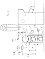
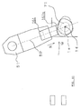
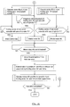
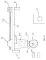
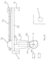
- FIG. 1 is a side view showing the overall structure of a first embodiment of the present invention;
- FIG. 2 is a partial view of FIG. 1 when viewed from an arrow E;
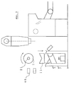
- FIG. 3 is a partial view of FIG. 1 when viewed from an arrow F;
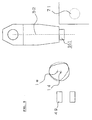
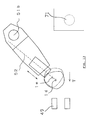
- FIG. 4 is a partial view of FIG. 1 when viewed from an arrow G;
- FIGS. 5 to 12 are diagrams showing the operation of the first embodiment;
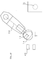
- FIG. 13 is a diagram showing the operation of another embodiment;
- FIG. 14 is a diagram showing the operation of another embodiment;
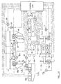
- FIG. 15 is a diagram of a structure for controlling the operation of the first embodiment;
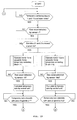
- FIGS. 16 to 21 show flow charts according to the first embodiment; and
- FIGS. 22 to 25 are diagrams showing the operation of another embodiment.
-
- An embodiment of the present invention will now be described with reference to FIGS. 1 to 4 and FIG. 15. The operation of the embodiments will now be described with reference to FIGS. 5 to 12 and FIGS. 16 to 21.
- FIG. 1 is a side view showing the overall structure of a veneer lathe incorporating a lathe charger according to the present invention. FIG. 2 is a partial view of FIG. 1 when viewed from an arrow E. FIG. 3 is a partial view of FIG. 1 when viewed from an arrow F. FIG. 4 is a partial view of FIG. 1 when viewed from an arrow G. FIG. 15 is a diagram of a structure for controlling the operation of this embodiment. FIGS. 5 to 12 are diagrams showing the operation of this embodiment. FIGS. 16 to 21 are flow charts.
- The lathe charger according to this embodiment incorporates an introducing
mechanism 103 for introducing raw wood, a temporary centering mechanism 111 for detecting a temporary center of two edges of the raw wood, a cutting-center centering mechanism 121 for detecting the cutting center in the two end surfaces of the raw wood andconveying mechanism 151 for conveying the raw wood, the cutting center of which has been detected, from the cutting-center centering mechanism 121 to aveneer lathe body 171. - As shown in FIG. 1, the introducing
mechanism 103 incorporates an introducingconveyor 3 capable of sequentially introducing theraw wood 1 and formed such that the introducingconveyor 3 is able to rotate and the rotation of the same can be braked. Moreover, the introducingmechanism 103 incorporates asensor 3a for detecting theraw wood 1, a fractionatingconveyor 5 capable of sequentially fractionating the sequentially introducedraw wood 1 and formed such that the fractionatingconveyor 5 is able to rotate and the rotation of the same can be braked. Moreover, the introducingmechanism 103 incorporates asensor 7 for detecting theraw wood 1. - As shown in FIG. 2, the temporary centering mechanism 111 incorporates a pair of right and left
temporary centering blocks inner slide surfaces 91 and 91a of a pair of right andleft frames 9 and 9a, each of thetemporary centering blocks feed screws 13 and 13a for thetemporary centering blocks feed screws 13 and 13a being ball screws or the like. The temporary centering mechanism 111 further incorporatesmotors feed screws 13 and 13a for thetemporary centering blocks motors feed screws 13 and 13a for thetemporary centering blocks displacement sensors 17 and 17a for thetemporary centering blocks displacement sensors 17 and 17a for thetemporary centering blocks sensors raw wood 1 which is moved upwards by thetemporary centering blocks - The lower ends of the
feed screws 13 and 13a are connected to axes of themotors feed screws 13 and 13a for thetemporary centering blocks feed screws 13 and 13a are received by thetemporary centering blocks motors feed screws 13 and 13a for thetemporary centering blocks frames 9 and 9a. - As shown in FIG. 3, the cutting-
center centering mechanism 121 is mainly composed of a movable centeringspindle 21 and a stationary centeringspindle 21a which is not moved. Each of thespindles raw wood 1. - The
movable centering spindle 21 is able to rotate and move in the axial direction thereof by dint of abearing 23 joined to amovable mount frame 39. Moreover, themovable centering spindle 21 is able to move in the axial direction thereof by dint of acylinder 25 joined to themovable mount frame 39. Themovable mount frame 39 is mounted onrails 41 arranged in a direction indicated by arrows T-U which is an example of a direction which intersects an extending/contracting direction of aholding arm 161 to be described later. Themovable mount frame 39 is reciprocated in a direction perpendicular to the direction of the axis of themovable centering spindle 21 by an operation mechanism. The operation mechanism incorporates afeed screw 43 for themovable mount frame 39, thefeed screw 43 being a ball screw or the like. Moreover, the operation mechanism incorporates amotor 45 for thefeed screw 43 for themovable mount frame 39, themotor 45 being a servo motor or the like. In addition, the operation mechanism incorporates asensor 47 for themovable mount frame 39, thesensor 47 being a rotary encoder or the like. A portion of thefeed screw 43 for themovable mount frame 39 is connected to a shaft of themotor 45 for thefeed screw 43 for themovable mount frame 39, while another portion is screwed in themovable mount frame 39. Themotor 45 for thefeed screw 43 for themovable mount frame 39 is secured to theframe 9 through a motor mounting frame 45a. Therails 41 penetrate themovable mount frame 39 so that themovable mount frame 39 is able to move along therails 41. - The rotative stationary centering
spindle 21a is able to move in the axial direction thereof by a bearing 23a joined to astationary mount frame 37. Moreover, the stationary centeringspindle 21a is able to move in the axial direction thereof by a cylinder 25a joined to thestationary mount frame 37. Moreover, the stationary centeringspindle 21a is also connected to amotor 33 which is capable of revolving the centeringspindle 21 and which is a servo motor or the like, the stationary centeringspindle 21a being connected through asprocket 31, achain 29 and asprocket 27. Thus, when themotor 33 is revolved, the stationary centeringspindle 21a is revolved.Reference numeral 35 represents a rotational-angle sensor 35 for the centeringspindle 21, the rotational-angle sensor 35 being a rotary encoder or the like. Thestationary mount frame 37 is joined to theframe 9, while themotor 33 for revolving the centeringspindle 21 is connected to theframe 9 through a motor mount frame 33a. - The stationary centering
spindle 21a is able to move in an axial direction with respect to thesprocket 31 and revolve together with thesprocket 31. -
Reference numeral 49 represents a raw-wood-profile sensor arranged to project a propagation medium, such as laser beams, electromagnetic waves or ultrasonic waves, to the outer surface of theraw wood 1 to use reflection of the propagation medium so as to detect the distance to the outer surface of theraw wood 1. The raw-wood-profile sensor 49 is joined to theframe 9. - As shown in FIG. 4, the conveying
mechanism 151 incorporates arotative support member 51,brackets 59 and 59a arranged to move along slide surfaces 51a formed on the lower surface of thesupport member 51 and holdingarms brackets 59 and 59a. The above-mentionedsupport member 51 is rotatably supported bybearings 53 and 53a. Amotor 55 for thesupport member 51 which is a servo motor or the like controls the reciprocating movement, while a rotational-angle sensor 57 for thesupport member 51 which is a rotary encoder or the like controls the rotational position. Thebrackets 59 and 59a are, bycylinders support member 51, reciprocated in a direction in which theraw wood 1 is held between thebrackets 59 and 59a through holdingarms arms feed screws 63 and 63a for the holdingarms motors arms arms motors brackets 59 and 59a. The leading ends of the holdingarms raw wood 1.Reference numeral sensors arms sensors - FIG. 15 shows a structure for controlling the operations of the introducing
mechanism 103, the temporary centering mechanism 111, the cutting-center centering mechanism 121 and the conveyingmechanism 151. A control unit is provided which causes the introducingconveyor 3, thefractionating conveyor 5 andmotors blocks sensor 3a and thedisplacement sensors 17 and 17a for the temporary centeringblocks sensors angle sensor 35 for the centeringspindle 21, thesensor 47 for themovable mount frame 39 and the raw-wood-profile sensor 49, themotor 33 for revolving the centeringspindle 21, themotor 45 for thefeed screw 43 for themovable mount frame 39 andcylinders 25 and 25a are automatically operated. In response to signals obtained from the rotational-angle sensor 57 for thesupport member 51 and thesensors arms cylinders motor 55 for thesupport member 51 andmotors arms - The operation of this embodiment having the above-mentioned structure will now be described with reference to FIGS. 5 to 12 showing the operations and flow charts shown in FIGS. 16 to 21.
- Referring to FIG. 1, when the
raw wood 1 on thefractionating conveyor 5 is detected by thesensor 3a, a detection signal is supplied to the control unit. In response to an output signal from the control unit, the introducingconveyor 3 is braked (see FIG. 16). - When the
raw wood 1 sequentially introduced by the claw 5a of thefractionating conveyor 5 is detected by thesensor 7, a detection signal is supplied to the control unit. In response to an output signal supplied from the control unit, thefractionating conveyor 5 is braked (see FIG. 17). - Simultaneously with the operation for braking the
fractionating conveyor 5, the temporary centering mechanisms 111 are operated. Although right and left temporary centering mechanisms 111 shown in FIG. 2 are individually operated, the operations are the same. Therefore, the operation of only the right-hand temporary centering mechanism 111 shown in FIG. 2 will now be described and that of the left-hand temporary centering mechanism is omitted from description. - Simultaneously with the operation for braking the
fractionating conveyor 5, themotor 15 for thefeed screw 13 for the temporary centeringblock 11 is operated in response to an output signal from the control unit. Thus, the temporary centeringblock 11 is moved upwards so that theraw wood 1 is moved upwards. Simultaneously, a signal is transmitted, to the control unit, from thedisplacement sensor 17 of the temporary centeringblock 11. - In FIG. 5, distance L1 from a position at which the
sensor 19 detects the upper portion of theraw wood 1 to the axis of the movable centeringspindle 21, distance L2 from the position at which thesensor 19 detects the upper portion of theraw wood 1 to the lower limit of the temporary centeringblock 11, the shape and dimensions of theraw wood 1 are previously communicated to the control unit. - When the
sensor 19 detects theraw wood 1 which is being moved upwards, a detection signal is supplied to the control unit. Since distance L3 for which theraw wood 1 has been moved upwards at the foregoing time has been communicated to the control unit by the signal transmitted from thedisplacement sensor 17, the control unit obtains the diameter of theraw wood 1 in response to the signal supplied from thesensor 19, the distances L2 and L3 and the shape and dimensions of the temporary centeringblock 11. Thus, the control unit obtains the temporary axis of theraw wood 1, and obtains radius L4 of the raw wood 1 (see FIG. 18). - Then, the temporary centering
block 11 in the state shown in FIG. 5 is furthermore upwards moved for distance expressed such that L4 + L1, and then themotor 15 for thefeed screw 13 for the temporary centeringblock 11 is braked. Thus, the temporary axis of theraw wood 1 is made coincide with the axis of the movable centering spindle 21 (see FIG. 6). - As described above, also the left-hand temporary centering mechanism 111 shown in FIG. 2 is operated similarly so that the
motor 15a is braked. As a result, the temporary axis of theraw wood 1 is made coincide with the axis of the stationary centeringspindle 21a. - After the
motors cylinders 25 and 25a are operated to forwards move the centeringspindles raw wood 1 is held by the centeringspindles - Then, the
motors blocks - After the downward movement has been completed, the
fractionating conveyor 5 is again rotated in response to an output signal from the control unit (see Fig. 17). - Simultaneously, the
motor 33 for revolving the centeringspindle 21 is revolved so that the heldraw wood 1 is revolved one time (see FIG. 7). At this time, a signal is supplied from the rotational-angle sensor 35 for the centeringspindle 21 to the control unit whenever the stationary centeringspindle 21a is revolved by an arbitrary number of revolutions. Simultaneously, in response to each signal, the raw-wood-profile sensor 49 transmits, to the control unit, a signal corresponding to the distance to the outer surface of theraw wood 1. In response to the signals supplied from the rotational-angle sensor 35 for the centeringspindle 21 and the raw-wood-profile sensor 49, the control unit obtains the cutting centers of the two end surfaces of the raw wood 1 (that is, between the end surface adjacent to the movable centeringspindle 21 and the end surface adjacent to the stationary centeringspindle 21a). - If the raw wood has a shape, for example, as shown in FIG. 8, the cutting center of the end surface adjacent to the movable centering
spindle 21 indicated by a solid line is obtained atposition 1d indicated by symbol + shown with a solid line. On the other hand, the cutting center of the end surface adjacent to the stationary centeringspindle 21a indicated by a dashed line is obtained at position 1e indicated by symbol + shown with a dashed line. FIG. 8 is a diagram of the ends surface of theraw wood 1 when viewed from the movable centeringspindle 21 in parallel with the centers of thespindles cutting centers 1d and 1e shown in FIG. 8 is defined to be an "imaginary straight line" according to the present invention. - After the cutting centers 1d and 1e have been obtained, the
motor 55 for thesupport member 51 is revolved to rotate thesupport member 51. Thus, the pair of the holdingarms spindles - Simultaneously, a signal is transmitted from the rotational-
angle sensor 57 for thesupport member 51 to the control unit. When the control unit has confirmed that theaxis 52 of the holding arm 161 (161a) has been made coincide with the cutting center 1e of the end surface of theraw wood 1 adjacent to the stationary centeringspindle 21a, the control unit revolves themotor 55 for thesupport member 51. The position (see FIGS. 9 and 20) is a position at which theraw wood 1 is held. - After the
motor 55 for thesupport member 51 has been braked, themotor 45 for thefeed screw 43 for themovable mount frame 39 is revolved so that a state in which theraw wood 1 is held between thespindles spindle 21 is moved in a direction indicated by an arrow T shown in FIG. 3. Simultaneously, thesensor 47 for themovable mount frame 39 transmits a signal to the control unit. - The
motor 45 for thefeed screw 43 for themovable mount frame 39 is revolved until the imaginary straight line passing through the cutting centers 1d and 1e coincides with theaxis 52 of the holding arm 161 (161a) as shown in FIG. 10. Thus, the movable centeringspindle 21 is moved. When the coincidence of the imaginary straight line with theaxis 52 of the holding arm has been confirmed in response to the signal supplied from thesensor 47 for themovable mount frame 39, themotor 45 for thefeed screw 43 for themovable mount frame 39 is braked. - Then, the rods of the
cylinders arms raw wood 1 is held between the holdingarms - Then, the rods of the
cylinders 25 and 25a are contracted so that thespindles raw wood 1 is released. Then, theraw wood 1 held between thespindles arms - Then, the
motor 55 for thesupport member 51 is again revolved so that thesupport member 51 is rotated in a direction opposite to the above-mentioned process. Thus, the pair of the holdingarms spindles 71 of the veneer lathe, that is, in a direction indicated by an arrow Q shown in FIG. 11. Simultaneously, the rotational-angle sensor 57 for thesupport member 51 transmits a signal to the control unit. - Then, the
motors arms arms sensors arms - When the control unit has confirmed that the cutting centers 1d and 1e of the
raw wood 1 have been made coincide with the axes of thespindles 71 in response to the signals supplied from the correspondingsensors arms motor 55 for thesupport member 51 and themotors arms - Then, the
spindles 71 of the veneer lathe are moved forwards so as to hold theraw wood 1 therebetween. Then, the rods of thecylinders raw wood 1 held between the holdingarms - Then, the holding
arms - The foregoing processes are repeated so that the cutting centers of the raw wood are obtained. Then, the raw wood is supplied in such a manner that the obtained cutting centers coincide with the axes of the spindles.
- The above-mentioned embodiment has the structure that the movement of the holding
arms support member 51 and the movement in the direction indicated by the arrow R (sometimes in the direction indicated by the arrow S because of contraction) by dint of extension of the holdingarms - The above-mentioned embodiment has the structure that the
axis 52 of the holdingarms support member 51, as shown in FIG. 9. Theaxis 52 is made not to pass through the rotational axis 51b by, in parallel, moving theaxis 52 of the holdingarms - The above-mentioned embodiment has the structure that the imaginary straight line and the
axis 52 of the holdingarms axis 52 of the holdingarms motor 55 for thesupport member 51 is braked in such a manner that the cutting center 1e is brought to a position apart from the axis of the holding arm for an arbitrary distance. The foregoing position is made to the position at which the raw wood is held. Then, themotor 45 for thefeed screw 43 for themovable mount frame 39 is revolved until the imaginary straight line 52a is brought to the position at which the imaginary straight line 52a is in parallel to the axis of the holding arm so that the movable centeringspindle 21 is moved. Thus, thecutting center 1d is moved in a direction indicated by an arrow T. Theraw wood 1 is supplied to the veneer lathe in such a manner that the cutting centers 1d and 1e coincide with the axis of thespindles 71 of the veneer lathe. - The mechanism for operating the movable centering
spindle 21 according to the foregoing embodiment has the structure that the movable centeringspindle 21 is mounted on themovable mount frame 39. Moreover, therails 41 are allowed to penetrate themovable mount frame 39. In addition, themovable mount frame 39 is enabled to reciprocate in a direction perpendicular to the axial direction of the movable centeringspindle 21 by thefeed screw 43 which is adapted to themovable mount frame 39 and which is a ball screw or the like, themotor 45 which is adapted to thefeed screw 43 for themovable mount frame 39 and which is a servo motor or the like and thesensor 47 which is adapted to themovable mount frame 39 and which is a rotary encoder or the like. The mechanism for operating the movable centeringspindle 21 is not limited to the above-mentioned mechanism. Any mechanism capable of controlling the position may be employed. - The above-mentioned embodiment has the structure that the means of the conveying
mechanism 151 for moving the holdingarm 161 is the mechanism capable of rotating about the rotational axis 51b. The mechanism may be a moving mechanism comprising rails for movement. - FIGS. 22 to 25 are diagrams showing the operations of an embodiment using the rails for movement. Referring to FIG. 22,
reference numeral 9 represents a frame, 161 represents a holding arm, 59 represents a bracket, 51 represents a support member, 49 represents a raw-wood-profile sensor and 71 represents a spindles for a veneer lathe. The above-mentioned structure is the same as that of the above-mentioned embodiment.Reference numeral 72 represents rails for movement arranged betweenframes 9. Thesupport member 51 is able to move while thesupport member 51 is guided by the rails for the movement.Reference numeral 73 represents a feed screw and 74 represents a motor for thesupport member 51. Thefeed screw 73 is able to revolve to the right and left by themotor 74 for thesupport member 51 so that thesupport member 51 engaged to thefeed screw 73 is moved. Note that the control mechanism for operating the above-mentioned elements has the same structure as that according to the above-mentioned embodiment. Therefore, the control mechanism is omitted from description. - Referring to FIG. 23, when coincidence of the
axis 52 of the holdingarm 161 with the cutting center 1e of the end surface adjacent to the stationary centering spindle has been confirmed, themotor 74 for thesupport member 51 is braked. Moreover, the movable centering spindle is moved to move the movable centering spindle until the imaginary straight line passing through the cutting centers 1d and 1e coincides with theaxis 52 of the holdingarm 161. Then, the unit for holding the raw wood is changed from the centering spindle to the holding arm 161 (see FIG. 24). - Then, the
motor 74 for thesupport member 51 is again revolved so that thesupport member 51 is moved in the direction opposite to that in the above-mentioned process. Thus, the holdingarm 161 is moved to thespindles 71 of the veneer lathe. Simultaneously, the length of the holdingarm 161 is adjusted so that the operation is continued until the twocutting centers 1d and 1e of the raw wood coincide with axes of the spindles 71 (see FIG. 25). - Since the present invention has the above-mentioned structure, the structure of an apparatus for correcting the position of the cutting centers of raw wood can be simplified. Moreover, the manufacturing cost can be reduced.
- Although the invention has been described in its preferred form with a certain degree of particularity, it is understood that the present disclosure of the preferred form can be changed in the details of construction and in the combination and arrangement of parts without departing from the spirit and the scope of the invention.
Claims (3)
- A lathe charger comprising:a pair of centering spindles (21, 21a) for holding end surfaces of raw wood (1);centering means (111) for automatically calculating cutting centers of the two end surfaces of the raw wood (1) held by the pair of the centering spindles (21, 21a);a pair of holding arms (161, 161a) for holding the raw wood (1) in place of the pair of the centering spindles (21, 21a); andmeans (51, 55, 72, 74) for moving the holding arms (161, 161a) in such a manner as to move the pair of holding arms (161, 161a) between the centering spindles (21, 21a) and spindles (71) of a veneer lathe for an arbitrary distance,wherein the pair of the holding arms (161, 161a) can be extended/contracted and one of the pair of the centering spindles (21, 21a) is structured to be capable of moving in a direction which intersects a direction in which the pair of the holding arms (161, 161a) are extended/contracted, andwherein a control mechanism is provided with which- - when one of the end surfaces is viewed in parallel with the axis of the centering spindles (21, 21a) in a state in which the raw wood (1) having cutting centers (1d, 1e) of the two end surfaces which have been calculated is held, one of the centering spindles (21, 21a) structured to be capable of moving is moved until an imaginary straight line passing through the two coincident cutting centers (1d, 1e) is made to be in parallel with the direction in which the holding arms (161, 161a) are extended/contracted at the position at which the holding arms (161, 161a) hold the raw wood (1),- - members for holding the raw wood (1) are changed from the centering spindles (21, 21a) to the holding arms (161, 161a) at the position to which the centering spindle (21, 21a) has been moved, and- - the holding arms (161, 161a) are extended/contracted and the holding arms (161, 161a) are moved to the spindles (71) of the veneer lathe by the means (51, 55, 72, 74) for moving the holding arms (161, 161a) so that the two cutting centers (1d, 1e) and the axes of the spindles (71) of the veneer lathe are made to coincide with each other.
- The lathe charger according to claim 1,
wherein the means (51, 55) for moving the holding arms (161, 161a) comprise a rotating mechanism (51, 55) arranged to be rotated about a rotational shaft (51b) thereof, and the imaginary straight line (52) passes through the axis of the rotational shaft (51b) when one of the end surfaces is viewed in parallel with the axis of the centering spindles (21, 21a). - The lathe charger according to claim 1,
wherein the means (51, 72, 74) for moving the holding arms (161, 161a) comprise a moving mechanism (51, 72, 74) having rails (72) for movement, and the imaginary straight line (52) passes through the axis of the holding arms (161, 161a) when one of the end surfaces is viewed in parallel with the axis of the centering spindles (21, 21a).
Applications Claiming Priority (3)
| Application Number | Priority Date | Filing Date | Title |
|---|---|---|---|
| JP225376/97 | 1997-08-21 | ||
| JP22537697 | 1997-08-21 | ||
| JP22537697A JP3676546B2 (en) | 1997-08-21 | 1997-08-21 | Race charger |
Publications (3)
| Publication Number | Publication Date |
|---|---|
| EP0897782A2 true EP0897782A2 (en) | 1999-02-24 |
| EP0897782A3 EP0897782A3 (en) | 2004-08-25 |
| EP0897782B1 EP0897782B1 (en) | 2008-04-23 |
Family
ID=16828391
Family Applications (1)
| Application Number | Title | Priority Date | Filing Date |
|---|---|---|---|
| EP98115446A Expired - Lifetime EP0897782B1 (en) | 1997-08-21 | 1998-08-17 | Lathe charger |
Country Status (8)
| Country | Link |
|---|---|
| US (1) | US6305448B1 (en) |
| EP (1) | EP0897782B1 (en) |
| JP (1) | JP3676546B2 (en) |
| CA (1) | CA2245327C (en) |
| DE (1) | DE69839380T2 (en) |
| ID (1) | ID22120A (en) |
| MY (1) | MY123943A (en) |
| TW (1) | TW393353B (en) |
Cited By (3)
| Publication number | Priority date | Publication date | Assignee | Title |
|---|---|---|---|---|
| EP0967058A2 (en) * | 1998-06-26 | 1999-12-29 | Meinan Machinery Works, Inc. | Apparatus and method for centering and feeding log |
| CN103203788A (en) * | 2012-12-27 | 2013-07-17 | 化州市中元木业有限公司 | Wood rotary cutting machine without clamp shaft |
| CN105563526A (en) * | 2016-03-04 | 2016-05-11 | 邵伟 | Stock bin system assisting industrial robot in automatic grabbing |
Families Citing this family (10)
| Publication number | Priority date | Publication date | Assignee | Title |
|---|---|---|---|---|
| JP2001232606A (en) * | 1999-12-14 | 2001-08-28 | Meinan Mach Works Inc | Apparatus and method for marking and supplying both butt ends of material wood |
| JP4603296B2 (en) * | 2004-06-07 | 2010-12-22 | 株式会社名南製作所 | Log centering and feeding device |
| US7007729B1 (en) * | 2004-06-09 | 2006-03-07 | Landers Adrian L | Log charging apparatus for sawmills |
| DE602006015767D1 (en) * | 2006-02-28 | 2010-09-09 | Meinan Machinery Works | Method and device for determining the optimal peeling axis of a tree trunk and its point with maximum radius with respect to the peeling axis |
| JP5562187B2 (en) * | 2010-06-09 | 2014-07-30 | 株式会社名南製作所 | Supplying raw wood to veneer lace |
| JP5612958B2 (en) * | 2010-08-06 | 2014-10-22 | 株式会社名南製作所 | Supplying raw wood to veneer lace |
| CN102357660B (en) * | 2011-09-21 | 2013-01-16 | 重庆银钢一通凸轮科技有限公司 | Automatic feed lathe |
| CN108115792A (en) * | 2016-11-30 | 2018-06-05 | 南京小脚印网络科技有限公司 | A kind of timber skinning machine |
| EP3917738A1 (en) * | 2019-01-30 | 2021-12-08 | Meinan Machinery Works, Inc. | Log feeding apparatus, log processing apparatus having the same, and method of controlling the same |
| WO2023281986A1 (en) * | 2021-07-05 | 2023-01-12 | 株式会社デンソー | Function component module for refrigeration cycle |
Citations (4)
| Publication number | Priority date | Publication date | Assignee | Title |
|---|---|---|---|---|
| US3037538A (en) * | 1957-01-07 | 1962-06-05 | Ernest J Graham | Device for alining end portions of a log to a chucking device therefor |
| US4246940A (en) * | 1978-07-17 | 1981-01-27 | Applied Theory Associates, Inc. | Veneer lathe charging apparatus and method for determining log spin axis |
| US4335763A (en) * | 1980-05-29 | 1982-06-22 | The Coe Manufacturing Co. | Veneer lathe charger having improved positioning for charger spindles |
| US5449030A (en) * | 1992-12-22 | 1995-09-12 | Kabushiki Kaisha Taiheiselsakusho | Methods and apparatus for centering a log and for supplying a log to be centered |
Family Cites Families (11)
| Publication number | Priority date | Publication date | Assignee | Title |
|---|---|---|---|---|
| US4965734A (en) * | 1977-02-25 | 1990-10-23 | Applied Theory, Division Of U.S.N.R., Inc. | Veneer lathe charging method for determining log spin axis |
| US4197888A (en) * | 1978-02-21 | 1980-04-15 | The Coe Manufacturing Company | Log centering apparatus and method using transmitted light and reference edge log scanner |
| US4378829A (en) * | 1981-05-28 | 1983-04-05 | Sun Studs, Inc. | Veneer lathe log charger system having enhanced accuracy and rate of production |
| US4384601A (en) | 1981-05-28 | 1983-05-24 | Sun Studs, Inc. | Veneer lathe log charger system having enhanced accuracy and rate of production |
| US4811776A (en) * | 1988-02-01 | 1989-03-14 | Bolton William E | Apparatus and method for centering logs |
| FI82627C (en) * | 1988-06-20 | 1991-04-10 | Raute Oy | SPINDELDREV FOER FANERSVARV. |
| US4884605A (en) * | 1989-02-03 | 1989-12-05 | The Coe Manufacturing Company | Lathe charger centering with log scanning during rotation and lateral movement of spindles |
| US4949769A (en) * | 1989-09-15 | 1990-08-21 | Cameron Robert E | Log delivery mechanism |
| JPH0460001A (en) | 1990-06-28 | 1992-02-26 | Norikichi Uzuka | Elastic fastening device for rail |
| US5421385A (en) * | 1993-10-29 | 1995-06-06 | The Coe Manufacturing Company | Method and apparatus for processing log for sawmill including end dogging carriage which rotationally repositions log to cutting position determined by computer after non-rotational scanning |
| US5518052A (en) * | 1995-04-04 | 1996-05-21 | Premier Gear & Machine Works | XY log charger |
-
1997
- 1997-08-21 JP JP22537697A patent/JP3676546B2/en not_active Expired - Fee Related
-
1998
- 1998-07-28 TW TW087112334A patent/TW393353B/en not_active IP Right Cessation
- 1998-08-05 US US09/129,277 patent/US6305448B1/en not_active Expired - Lifetime
- 1998-08-17 EP EP98115446A patent/EP0897782B1/en not_active Expired - Lifetime
- 1998-08-17 DE DE69839380T patent/DE69839380T2/en not_active Expired - Fee Related
- 1998-08-19 ID IDP981145A patent/ID22120A/en unknown
- 1998-08-19 MY MYPI98003783A patent/MY123943A/en unknown
- 1998-08-19 CA CA002245327A patent/CA2245327C/en not_active Expired - Fee Related
Patent Citations (5)
| Publication number | Priority date | Publication date | Assignee | Title |
|---|---|---|---|---|
| US3037538A (en) * | 1957-01-07 | 1962-06-05 | Ernest J Graham | Device for alining end portions of a log to a chucking device therefor |
| US4246940A (en) * | 1978-07-17 | 1981-01-27 | Applied Theory Associates, Inc. | Veneer lathe charging apparatus and method for determining log spin axis |
| US4335763A (en) * | 1980-05-29 | 1982-06-22 | The Coe Manufacturing Co. | Veneer lathe charger having improved positioning for charger spindles |
| US4383560A (en) * | 1980-05-29 | 1983-05-17 | The Coe Manufacturing Company | Lathe charger having directionally limited adjustment of scanning spindles |
| US5449030A (en) * | 1992-12-22 | 1995-09-12 | Kabushiki Kaisha Taiheiselsakusho | Methods and apparatus for centering a log and for supplying a log to be centered |
Cited By (5)
| Publication number | Priority date | Publication date | Assignee | Title |
|---|---|---|---|---|
| EP0967058A2 (en) * | 1998-06-26 | 1999-12-29 | Meinan Machinery Works, Inc. | Apparatus and method for centering and feeding log |
| EP0967058A3 (en) * | 1998-06-26 | 2001-12-12 | Meinan Machinery Works, Inc. | Apparatus and method for centering and feeding log |
| CN103203788A (en) * | 2012-12-27 | 2013-07-17 | 化州市中元木业有限公司 | Wood rotary cutting machine without clamp shaft |
| CN103203788B (en) * | 2012-12-27 | 2015-12-09 | 化州市中元木业有限公司 | A kind of non-fastenning-shaft timber wood rotary shaver |
| CN105563526A (en) * | 2016-03-04 | 2016-05-11 | 邵伟 | Stock bin system assisting industrial robot in automatic grabbing |
Also Published As
| Publication number | Publication date |
|---|---|
| CA2245327C (en) | 2005-10-11 |
| CA2245327A1 (en) | 1999-02-21 |
| DE69839380D1 (en) | 2008-06-05 |
| JPH1158327A (en) | 1999-03-02 |
| ID22120A (en) | 1999-09-09 |
| US6305448B1 (en) | 2001-10-23 |
| JP3676546B2 (en) | 2005-07-27 |
| MY123943A (en) | 2006-06-30 |
| EP0897782A3 (en) | 2004-08-25 |
| DE69839380T2 (en) | 2009-05-20 |
| TW393353B (en) | 2000-06-11 |
| EP0897782B1 (en) | 2008-04-23 |
Similar Documents
| Publication | Publication Date | Title |
|---|---|---|
| EP0897782B1 (en) | Lathe charger | |
| CA2583166C (en) | Machining and conveying apparatus | |
| US20010008231A1 (en) | Apparatus and control system for laser welding | |
| JPS6336888B2 (en) | ||
| JPH03221311A (en) | Mealing type travelling steel pipe cutting machine | |
| US10315255B2 (en) | Machine tool with an assembly configuration with a cantilevered tool | |
| CN101015864A (en) | Chuck and method thereof | |
| EP1277537A1 (en) | Machine for cutting pipes with different cross-sections and diameters by means of a laser beam | |
| US6176282B1 (en) | Apparatus and method for centering and feeding log | |
| JP2678894B2 (en) | Segment assembly equipment for shield machine | |
| JPH0156852B2 (en) | ||
| JP2000210889A (en) | Industrial robot | |
| EP1115516B1 (en) | Apparatus and method for bending tubular or rod-shaped material | |
| JPH077808U (en) | Machine tool axial misalignment correction mechanism | |
| US6681819B2 (en) | Rotating shearing machine for the production of sheared wooden pieces from logs and having log inclination movement | |
| JPH061182B2 (en) | Cam surface inspection device | |
| JP3350913B2 (en) | Segment assembly positioning method | |
| WO2021205492A1 (en) | Lathe charger control device, lathe charger provided with same and lathe charger control method | |
| JPH0885091A (en) | Rotational error correcting device of robot | |
| JPS59220231A (en) | Carrying device of work | |
| JP2577092B2 (en) | Grinding equipment | |
| JPH04111930A (en) | Positioning device in metal plate working device | |
| JPH0518196A (en) | Automatic segment assembling device | |
| JP2022147597A (en) | Inspection device and inspection method, and manufacturing method for products, bearings, vehicles, and machines | |
| CN1154219A (en) | Apparatus for rotation and sidewise transport of rod-shaped articles of tobacco processing industry |
Legal Events
| Date | Code | Title | Description |
|---|---|---|---|
| PUAI | Public reference made under article 153(3) epc to a published international application that has entered the european phase |
Free format text: ORIGINAL CODE: 0009012 |
|
| AK | Designated contracting states |
Kind code of ref document: A2 Designated state(s): AT BE CH CY DE DK ES FI FR GB GR IE IT LI LU MC NL PT SE |
|
| AX | Request for extension of the european patent |
Free format text: AL;LT;LV;MK;RO;SI |
|
| PUAL | Search report despatched |
Free format text: ORIGINAL CODE: 0009013 |
|
| AK | Designated contracting states |
Kind code of ref document: A3 Designated state(s): AT BE CH CY DE DK ES FI FR GB GR IE IT LI LU MC NL PT SE |
|
| AX | Request for extension of the european patent |
Extension state: AL LT LV MK RO SI |
|
| 17P | Request for examination filed |
Effective date: 20041123 |
|
| AKX | Designation fees paid |
Designated state(s): DE FI IT |
|
| RBV | Designated contracting states (corrected) |
Designated state(s): DE FI IT |
|
| GRAP | Despatch of communication of intention to grant a patent |
Free format text: ORIGINAL CODE: EPIDOSNIGR1 |
|
| GRAS | Grant fee paid |
Free format text: ORIGINAL CODE: EPIDOSNIGR3 |
|
| GRAA | (expected) grant |
Free format text: ORIGINAL CODE: 0009210 |
|
| AK | Designated contracting states |
Kind code of ref document: B1 Designated state(s): DE FI IT |
|
| REF | Corresponds to: |
Ref document number: 69839380 Country of ref document: DE Date of ref document: 20080605 Kind code of ref document: P |
|
| PLBE | No opposition filed within time limit |
Free format text: ORIGINAL CODE: 0009261 |
|
| STAA | Information on the status of an ep patent application or granted ep patent |
Free format text: STATUS: NO OPPOSITION FILED WITHIN TIME LIMIT |
|
| 26N | No opposition filed |
Effective date: 20090126 |
|
| PG25 | Lapsed in a contracting state [announced via postgrant information from national office to epo] |
Ref country code: DE Free format text: LAPSE BECAUSE OF NON-PAYMENT OF DUE FEES Effective date: 20090303 |
|
| PGFP | Annual fee paid to national office [announced via postgrant information from national office to epo] |
Ref country code: IT Payment date: 20160823 Year of fee payment: 19 Ref country code: FI Payment date: 20160822 Year of fee payment: 19 |
|
| PG25 | Lapsed in a contracting state [announced via postgrant information from national office to epo] |
Ref country code: FI Free format text: LAPSE BECAUSE OF NON-PAYMENT OF DUE FEES Effective date: 20170817 |
|
| PG25 | Lapsed in a contracting state [announced via postgrant information from national office to epo] |
Ref country code: IT Free format text: LAPSE BECAUSE OF NON-PAYMENT OF DUE FEES Effective date: 20170817 |