EP0897261B1 - Vorrichtung und verfahren zum melken von tieren - Google Patents
Vorrichtung und verfahren zum melken von tieren Download PDFInfo
- Publication number
- EP0897261B1 EP0897261B1 EP97919754A EP97919754A EP0897261B1 EP 0897261 B1 EP0897261 B1 EP 0897261B1 EP 97919754 A EP97919754 A EP 97919754A EP 97919754 A EP97919754 A EP 97919754A EP 0897261 B1 EP0897261 B1 EP 0897261B1
- Authority
- EP
- European Patent Office
- Prior art keywords
- passageway
- spurring
- milking
- movable
- animals
- Prior art date
- Legal status (The legal status is an assumption and is not a legal conclusion. Google has not performed a legal analysis and makes no representation as to the accuracy of the status listed.)
- Expired - Lifetime
Links
Images

Classifications
-
- A—HUMAN NECESSITIES
- A01—AGRICULTURE; FORESTRY; ANIMAL HUSBANDRY; HUNTING; TRAPPING; FISHING
- A01K—ANIMAL HUSBANDRY; AVICULTURE; APICULTURE; PISCICULTURE; FISHING; REARING OR BREEDING ANIMALS, NOT OTHERWISE PROVIDED FOR; NEW BREEDS OF ANIMALS
- A01K1/00—Housing animals; Equipment therefor
- A01K1/12—Milking stations
-
- A—HUMAN NECESSITIES
- A01—AGRICULTURE; FORESTRY; ANIMAL HUSBANDRY; HUNTING; TRAPPING; FISHING
- A01K—ANIMAL HUSBANDRY; AVICULTURE; APICULTURE; PISCICULTURE; FISHING; REARING OR BREEDING ANIMALS, NOT OTHERWISE PROVIDED FOR; NEW BREEDS OF ANIMALS
- A01K15/00—Devices for taming animals, e.g. nose-rings or hobbles; Devices for overturning animals in general; Training or exercising equipment; Covering boxes
- A01K15/02—Training or exercising equipment, e.g. mazes or labyrinths for animals ; Electric shock devices; Toys specially adapted for animals
Definitions
- the invention concerns a device according to the preamble of claim 1.
- a device is known from EP 0432148, see figure 9 and 10.
- spurring means for pushing animals through a passage onto a ramp to enter container 200
- spurring means for pushing animals through a passage 232 after they have left the container via the ramp 231.
- the disadvantage of the known design is that the spurring means require complicated constructions for mounting and the pushing elements can only push animals along a limited path.
- the invention has the object to avoid these disadvantages and therefor the device is made according to the characterizing part of claim 1.
- the spurring means By mounting the spurring means on the sides of the passageway they can be mounted easily without the need of complicated constructions.
- the device is made according to claim 2.
- the spurring member is supported in an advantageous way when protruding in the passageway and when it might touch animals.
- the device is made according to claim 3. In this way the sensors can be mounted easily and risk of contamination is reduced.
- the device is made according to claim 4. In this way accurate detection of animals in front of the milking stalls is possible in an easy way.
- the device is made according to claim 5.
- the spurring means can follow an animal accurately, thereby spurring it to leave the passageway with minimal loss of time.
- the device is made according to claim 5.
- the spurring means can follow an animal accurately, thereby spurring it to leave the passageway with minimal loss of time.
- the device is made according to claim 6. In this way the animals can be spurred more effectively.
- the device is made according to claim 7. In this way an animal can be spurred effectively without the use of complicated machinery.
- the invention also concerns a method using the device according to claim 8. In this way animals, may walk according to their own speed towards the accommodation area and they can be taught that standing still is not allowed.
- a method according to claim 9 is used. In this way it is prevented that backward animals are spurred while they are prevented to move as they cannot pass forward animals.
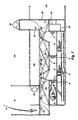
- a first milking stall 1, a second milking stall 2 and a third milking stall 3 are placed successively in the length.
- a milking robot 6 can move on a rail along one of the long sides. Milking robot 6 can travel along the three milking stalls and can arrange teat cups placed on a milking rack 5 onto the udder of a cow present in one of the milking stalls 1, 2 or 3, wherein the animal, which during milking can eat from a feed trough 4, can be milked in the known manner such as is shown for instance in figure 1 in the first milking stall 1.
- the cows present in a waiting area 9 walk in a walking direction A through an access gate 15 via a passageway 10 to one of the milking stalls and enter the milking stall, for instance as shown in figure 1 the second milking stall 2, through an entrance gate 7. After milking has ended and the teat cups released from the udder an exit gate 8 is opened, as shown at the third milking stall 3.
- the cow Simultaneously with opening of exit gate 8 the cow is urged out of the milking stall with pushers (not shown) and will enter and walk out of passageway 10 and walk via a one-way gate 18 to an accommodation area 11.
- pushers not shown
- the cow can also be guided to a segregation area 12 or it is guided back to waiting area 9 via a return path 13 and a one-way gate 18 by adjusting a return gate 17.
- the diverse components of the device are controlled by a control 14 placed in an auxiliary area 19.
- detection beams 20 Arranged in passageway 10 in front of the milking stalls are about two detection beams 20 per milking stall which consist for instance of infrared beams which run from an infrared transmitter (not shown) to an infrared receiver and with which the presence of cows in passageway 10 can be detected.
- the detection beams 20 are placed such that opening or closing of for instance an entrance gate 7 or an exit gate 8 does not result in a mistaken detection of for instance an animal.
- the infrared transmitters and receivers are connected to the control 14 which controls the different components of the device and in which inter alia timers are incorporated which can monitor how long ago an animal was driven out of the milking stall or how long one or more of the detection beams 20 have been interrupted. As long as animals which have been milked are standing in passageway 10 no new animal will be admitted via access gate 15 since it is for instance not permitted for the entrance gate 7 of the third milking stall 3 to be opened if an already milked animal which has for instance just left the first milking stall 1 can thereby enter the third milking stall 3.
- the device can also be embodied with other detection means for establishing the presence of cows in passageway 10. It is for instance possible to embody the detection means by arranging sensors in the ceiling along the whole length of passageway 10 which can determine the presence of animals. This is possible for instance with ultrasonic distance sensors, with passive infrared detectors or with other known detection means with which the presence of living creatures in a space can be determined.
- the advantage of detectors arranged in a high position is that they are placed less vulnerably, will become fouled less quickly and the laying of cabling is simpler.
- the spurring means are arranged along one of the sides of passageway 10 and comprise, as shown in figures 2-4, an endless cord 21, for instance a woven cord, which is made conductive in known manner by interweaving stainless steel wire of 0.1 mm diameter therein and which is stretched round two guide wheels 22. These latter can rotate in a direction C and are driven by a drive 24 which is connected to one of the guide wheels 22 by means of a drive belt 23. In respect of cleaning of the milking stalls and passageway 10 the drive 24 is placed in a high position so that it can remain dry during spray cleaning.
- a clamping block 25 Fixed round the endless cord 21 is a clamping block 25, the sides of which are placed between an upper guide 26 during movement in a spurring direction B and are thereby guided such that a probe 37 fixed to clamping block 25 protrudes into the passageway 10. After passing over guide wheel 22 the clamping block 25 is also guided by a lower guide 27 during the movement in a return direction D such that the probe 37 hangs downward.
- Guides 26 and 27 herein ensure that animals and humans moving in the passageway 10 cannot accidentally contact the endless cord.
- a guide cam 30 is placed round one of the guide wheels 22.
- probe 37 During use the probe 37 lies at rest parallel to the wall at an end switch 28. At the moment cows must be prompted to move, the drive 24 is switched on by control 14 and guide wheel 22 begins to rotate in the direction C. Probe 37 will first move in direction D and, under the influence of guide cam 30, be carried between the guide 26 and move in the direction B. Probe 37 herein protrudes into the passageway and moves at a speed of about 17 m per minute, this speed being such that a cow can ensure that it is not touched by probe 37.
- Probe 37 moves in direction D until the drive is brought to a stop by end switch 28 when it detects probe 37.
- a high-voltage generator 36 will be switched on simultaneously with switch-on of drive 24, wherein the high voltage, for instance 10,000 V, is conducted via a high-voltage cable 35 and a wiper contact 29 to the endless cord 21.
- the high voltage for instance 10,000 V
- the clamping block 25 of probe 37 which is clamped round cord 21 Fixed to the clamping block 25 of probe 37 which is clamped round cord 21 is a protective sheath 31 having therein a conductive core 32, which core protrudes out of protective sheath 31 on the side remote from clamping block 25 and can there thus be live with high voltage.
- This high voltage can contact the cows which are thereby strongly stimulated to walk away from the probe 37 and leave the passageway 10.
- gate 33 is provided with an insulating sheath 34.
- means can be arranged whereby the probe 37 will begin to flail mechanically during movement and thereby encourage the animals to move.
- This is possible for instance by mounting a toothed belt on the upper guide 26, which belt coacts with mechanical means (not shown) arranged in the probe which consist for instance of a pinion in engagement with the toothed belt and a rotating flexible shaft to which flailing wires are fastened.
- Provisions can also be arranged in the control which ensure that, if one of the entrance gates 7 or exit gates 8 opens and thereby obstructs the passage in passageway 10, the probe 37 then comes temporarily to a stop until the gate is closed again, the passageway 10 is again clear and the cows can again walk further.
- the detection means are arranged on the spurring means.
- This device operates as follows: on probe 37 of figures 2-4 is arranged a sensor which gives a signal to the control 14 when probe 37 arrives close to or against a cow.
- the probe 37 periodically moving rapidly in walking direction B then acquires a lower speed so that the cow can continue to walk ahead of probe 37.
- Probe 37 can thus move at two speeds, wherein the high speed is switched on periodically in order to detect whether animals are standing in passageway 10 and, under the influence of the presence of animals, this high speed slows to below the walking speed of the cows.
- the invention is not limited to the embodiments discussed here.
- the detection means and spurring means can thus be arranged at a plurality of locations, i.e. everywhere animals can obstruct each other's passage.
Landscapes
- Life Sciences & Earth Sciences (AREA)
- Environmental Sciences (AREA)
- Zoology (AREA)
- Animal Husbandry (AREA)
- Biodiversity & Conservation Biology (AREA)
- Health & Medical Sciences (AREA)
- General Health & Medical Sciences (AREA)
- Physical Education & Sports Medicine (AREA)
- Animal Behavior & Ethology (AREA)
- Housing For Livestock And Birds (AREA)
Claims (9)
- Vorrichtung zum Melken von Tieren mit einem Melkstand oder mehreren Melkständen (1, 2, 3), die mit beweglichen Austrittstoren (8) versehen sind, mit einem Gang (10) entlang der Austrittstore, der die Austrittstore mit einem Unterkunftsbereich (11) verbindet, mit Detektormitteln (20) zur Feststellung des Vorhandenseins von Tieren in dem Gang und mit Vortriebsmitteln (37) zum Vorantreiben der im Gang festgestellten Tiere nach dem Unterkunftsbereich (11) hin,
dadurch gekennzeichnet, daß die Vortriebsmittel längs einer der Seiten des Ganges angeordnet sind und einen endlosen Riemen (21) aufweisen, der über drehbare Räder (22) geführt ist und daß ein bewegliches Vortriebsglied (37) an einem Klemmblock (25) am endlosen Riemen fixiert ist. - Vorrichtung nach Anspruch 1,
dadurch gekennzeichnet, daß Führungsmittel (26) auf der Seite des Ganges angeordnet sind, die den Klemmkörper (25) abstützen, wenn das Vortriebsglied (31) in den Gang (10) vorsteht. - Vorrichtung nach den Ansprüchen 1 oder 2,
dadurch gekennzeichnet, daß die Detektormittel über dem Gang (10) angeordnet sind und Ultraschallsensoren oder Infrarotsensoren aufweisen. - Vorrichtung nach den Ansprüchen 1 oder 2,
dadurch gekennzeichnet, daß die Detektormittel, die vor den Melkständen (1, 2, 3) angeordnet sind, zwei Detektorstrahlen (20) für jeden Melkstand aufweisen. - Vorrichtung nach den Ansprüchen 1 oder 2,
dadurch gekennzeichnet, daß die Detektormittel auf dem beweglichen Vortriebsglied (31) angeordnet sind und daß die Geschwindigkeit der beweglichen Vortriebsmittel durch diese Detektormittel gesteuert wird. - Vorrichtung nach einem der vorhergehenden Ansprüche,
dadurch gekennzeichnet, daß das bewegliche Vortriebsglied (31) elektrisch leitfähig und mit einem Hochspannungsgenerator (36) verbunden ist. - Vorrichtung nach einem der vorhergehenden Ansprüche,
dadurch gekennzeichnet, daß das bewegliche Vortriebsglied (31) mechanische Rütteleinrichtungen enthält, die durch die Bewegung des Vortriebsgliedes aktiviert werden. - Verfahren zur Benutzung der Vorrichtung nach einem der vorhergehenden Ansprüche,
dadurch gekennzeichnet, daß das bewegliche Vortriebsglied (31) längs des Ganges (10) bewegt wird, nachdem festgestellt wurde, daß ein Tier über eine festgesetzte Zeit hinaus noch in dem Gang stillsteht. - Verfahren nach Anspruch 8,
dadurch gekennzeichnet, daß die Bewegung des Vortriebsgliedes (31) nicht angeschaltet wird, nachdem ein zweites Tier im Gang festgestellt wurde.
Applications Claiming Priority (3)
| Application Number | Priority Date | Filing Date | Title |
|---|---|---|---|
| NL1002968 | 1996-04-29 | ||
| NL1002968A NL1002968C2 (nl) | 1996-04-29 | 1996-04-29 | Inrichting en werkwijze voor het melken van dieren. |
| PCT/NL1997/000234 WO1997040663A1 (en) | 1996-04-29 | 1997-04-29 | A device and method for milking animals |
Publications (2)
| Publication Number | Publication Date |
|---|---|
| EP0897261A1 EP0897261A1 (de) | 1999-02-24 |
| EP0897261B1 true EP0897261B1 (de) | 2002-12-04 |
Family
ID=19762745
Family Applications (1)
| Application Number | Title | Priority Date | Filing Date |
|---|---|---|---|
| EP97919754A Expired - Lifetime EP0897261B1 (de) | 1996-04-29 | 1997-04-29 | Vorrichtung und verfahren zum melken von tieren |
Country Status (6)
| Country | Link |
|---|---|
| US (1) | US6213052B1 (de) |
| EP (1) | EP0897261B1 (de) |
| JP (1) | JP2001503604A (de) |
| DE (1) | DE69717618T2 (de) |
| NL (1) | NL1002968C2 (de) |
| WO (1) | WO1997040663A1 (de) |
Families Citing this family (10)
| Publication number | Priority date | Publication date | Assignee | Title |
|---|---|---|---|---|
| SE0102162D0 (sv) * | 2001-06-19 | 2001-06-19 | Delaval Holding Ab | System and method for milking animals |
| SE0203580D0 (sv) * | 2002-12-03 | 2002-12-03 | Delaval Holding Ab | An apparatus for detecting animals |
| SE528563C2 (sv) * | 2004-12-20 | 2006-12-19 | Delaval Holding Ab | Mjölkningsarrangemang |
| WO2008030156A1 (en) * | 2006-09-05 | 2008-03-13 | Delaval Holding Ab | Milking arrangement and method |
| NL1036114C (nl) * | 2008-10-24 | 2010-04-27 | Lely Patent Nv | Hekstelsel om een dier toegang te verschaffen tot een ruimte. |
| NL1037471C2 (nl) * | 2009-11-13 | 2011-05-16 | Lely Patent Nv | Dierpositiesensor. |
| NL2015337B1 (nl) * | 2015-08-24 | 2017-03-16 | Lely Patent Nv | Systeem en werkwijze voor het melken van een groep melkdieren. |
| US10638718B2 (en) | 2015-09-21 | 2020-05-05 | Afimilk Agricultural Cooperative Ltd. | Mobile milking robot with minimal footprint |
| US11006613B2 (en) | 2015-09-21 | 2021-05-18 | Afimilk Agricultural Cooperative Ltd. | Mobile milking robot with minimal footprint |
| US11019801B2 (en) | 2015-09-21 | 2021-06-01 | Afimilk Agricultural Cooperative Ltd. | Multiple cell voluntary milking method and system, comprising a mobile milking robot having a minimal footprint |
Family Cites Families (17)
| Publication number | Priority date | Publication date | Assignee | Title |
|---|---|---|---|---|
| US2269012A (en) * | 1940-03-18 | 1942-01-06 | Carli John J De | Individual stall system for cow milking |
| US3460515A (en) * | 1965-06-25 | 1969-08-12 | Hahn Enterprises Inc | Milking system |
| US3703884A (en) * | 1970-04-21 | 1972-11-28 | Richard E Maddalena | Automated dairy barn milk stall |
| US3783830A (en) * | 1970-08-10 | 1974-01-08 | Ross Holm Division | Automatic milking barn |
| AU522272B2 (en) * | 1978-01-10 | 1982-05-27 | Alf Hannaford & Co. Pty. Ltd. | Provoking forward movement of sheep |
| NL184864C (nl) * | 1981-10-23 | 1989-12-01 | Wopereis Agrarische Systemen B | Inrichting voor het vanuit een ruimte, zoals een met ten minste een rij naast elkaar gelegen ligboxen en een achter de rij resp. de rijen ligboxen verlopende loopgang uitgeruste loopstal, naar een andere ruimte, zoals een melkstal, opdrijven van vee. |
| NL8601297A (nl) * | 1986-05-22 | 1987-12-16 | Nedap Nv | Toepassing van een voor elk dier van een kudde uniek geluidssignaal voor het op een vooraf bepaald moment automatisch uitvoeren van een verzorgingsfunctie, zoals voeren of afzonderen van het betreffende individu. |
| NL8602942A (nl) | 1986-11-19 | 1988-06-16 | Multinorm Bv | Verplaatsbare ruimte waarin een inrichting voor het automatisch melken van een beest is opgesteld. |
| FR2621345B1 (fr) * | 1987-10-02 | 1992-11-27 | Est Lait | Dispositif permettant de contraindre des animaux rassembles dans un parc d'attente a avancer vers une porte |
| NL9200418A (nl) * | 1992-03-06 | 1993-10-01 | Lely Nv C Van Der | Inrichting voor het melken van dieren. |
| DE4328666C1 (de) * | 1993-08-26 | 1994-12-08 | Westfalia Separator Ag | Vorrichtung zur Tiersortierung |
| NL9401238A (nl) * | 1994-07-28 | 1996-03-01 | Prolion Bv | Inrichting voor het automatisch melken van dieren. |
| US5615637A (en) * | 1995-03-27 | 1997-04-01 | Dec International, Inc. | Automated milking parlor |
| US5628284A (en) * | 1995-06-06 | 1997-05-13 | Alfa Laval Agri, Inc. | Livestock cutter gate apparatus |
| NL1004917C1 (nl) * | 1996-04-09 | 1997-10-14 | Prolion Bv | Inrichting en werkwijze voor het automatisch melken van dieren. |
| US5803015A (en) * | 1997-01-21 | 1998-09-08 | Alfa Laval Agri Inc. | Dairy parlor entry gate |
| US5959526A (en) * | 1997-09-02 | 1999-09-28 | Dec International, Inc. | Milking parlor cow identification correction method |
-
1996
- 1996-04-29 NL NL1002968A patent/NL1002968C2/nl not_active IP Right Cessation
-
1997
- 1997-04-29 DE DE69717618T patent/DE69717618T2/de not_active Expired - Lifetime
- 1997-04-29 EP EP97919754A patent/EP0897261B1/de not_active Expired - Lifetime
- 1997-04-29 JP JP53875797A patent/JP2001503604A/ja active Pending
- 1997-04-29 WO PCT/NL1997/000234 patent/WO1997040663A1/en not_active Ceased
- 1997-04-29 US US09/171,888 patent/US6213052B1/en not_active Expired - Lifetime
Also Published As
| Publication number | Publication date |
|---|---|
| NL1002968C2 (nl) | 1997-11-06 |
| EP0897261A1 (de) | 1999-02-24 |
| JP2001503604A (ja) | 2001-03-21 |
| WO1997040663A1 (en) | 1997-11-06 |
| US6213052B1 (en) | 2001-04-10 |
| DE69717618D1 (de) | 2003-01-16 |
| DE69717618T2 (de) | 2003-09-18 |
Similar Documents
| Publication | Publication Date | Title |
|---|---|---|
| US6257169B1 (en) | Milking device with control system and sensors | |
| US6050219A (en) | Apparatus for milking animals | |
| EP0772389B2 (de) | Vorrichtung und verfahren zum automatischen melken von tieren | |
| EP0591288B1 (de) | Automatisches melken | |
| EP0897261B1 (de) | Vorrichtung und verfahren zum melken von tieren | |
| EP0689762B1 (de) | Gerät zum automatischen Melken von Tieren | |
| NL1002792C2 (nl) | Constructie met een inrichting voor het melken van dieren. | |
| EP0194729B1 (de) | Gerät zum Melken von Tieren | |
| NL1006934C2 (nl) | Melkinstallatie. | |
| US7690327B2 (en) | Milking box expulsion system | |
| EP0636312B1 (de) | Vorrichtung zum automatischen Melken von Tieren | |
| EP0990385B1 (de) | Konstruktion zum Melken von Tieren | |
| US11234412B2 (en) | Expelling device and a milking arrangement provided with such a device | |
| EP0205219B1 (de) | Fütterungsstand für Vieh | |
| US6779484B2 (en) | Milking system | |
| NL8900415A (nl) | Verblijfplaats voor een aantal dieren, in het bijzonder melkdieren. | |
| EP0886466B1 (de) | Konstruktiom mit einem gerät zum automatischen melken von tieren | |
| WO2000070934A1 (en) | Animal stall with gate adapted for goading the animal | |
| WO2024218107A1 (en) | Hoof spraying arrangement, method for the cleaning of a hoof and use thereof in the treatment and prevention of hoof infections in animals | |
| WO1999041977A1 (en) | Device and method for the automatic milking of animals |
Legal Events
| Date | Code | Title | Description |
|---|---|---|---|
| PUAI | Public reference made under article 153(3) epc to a published international application that has entered the european phase |
Free format text: ORIGINAL CODE: 0009012 |
|
| 17P | Request for examination filed |
Effective date: 19981005 |
|
| AK | Designated contracting states |
Kind code of ref document: A1 Designated state(s): DE FR GB NL |
|
| 17Q | First examination report despatched |
Effective date: 20000118 |
|
| GRAG | Despatch of communication of intention to grant |
Free format text: ORIGINAL CODE: EPIDOS AGRA |
|
| GRAG | Despatch of communication of intention to grant |
Free format text: ORIGINAL CODE: EPIDOS AGRA |
|
| GRAH | Despatch of communication of intention to grant a patent |
Free format text: ORIGINAL CODE: EPIDOS IGRA |
|
| GRAH | Despatch of communication of intention to grant a patent |
Free format text: ORIGINAL CODE: EPIDOS IGRA |
|
| GRAA | (expected) grant |
Free format text: ORIGINAL CODE: 0009210 |
|
| AK | Designated contracting states |
Kind code of ref document: B1 Designated state(s): DE FR GB NL |
|
| REG | Reference to a national code |
Ref country code: GB Ref legal event code: FG4D |
|
| REF | Corresponds to: |
Ref document number: 69717618 Country of ref document: DE Date of ref document: 20030116 |
|
| ET | Fr: translation filed | ||
| PLBE | No opposition filed within time limit |
Free format text: ORIGINAL CODE: 0009261 |
|
| STAA | Information on the status of an ep patent application or granted ep patent |
Free format text: STATUS: NO OPPOSITION FILED WITHIN TIME LIMIT |
|
| 26N | No opposition filed |
Effective date: 20030905 |
|
| REG | Reference to a national code |
Ref country code: GB Ref legal event code: 732E Free format text: REGISTERED BETWEEN 20100204 AND 20100211 |
|
| NLS | Nl: assignments of ep-patents |
Owner name: GEA WESTFALIASURGE GMBH Effective date: 20100120 |
|
| REG | Reference to a national code |
Ref country code: FR Ref legal event code: TP |
|
| PGFP | Annual fee paid to national office [announced via postgrant information from national office to epo] |
Ref country code: DE Payment date: 20120509 Year of fee payment: 16 Ref country code: NL Payment date: 20120514 Year of fee payment: 16 |
|
| PGFP | Annual fee paid to national office [announced via postgrant information from national office to epo] |
Ref country code: GB Payment date: 20120425 Year of fee payment: 16 |
|
| REG | Reference to a national code |
Ref country code: NL Ref legal event code: V1 Effective date: 20131101 |
|
| GBPC | Gb: european patent ceased through non-payment of renewal fee |
Effective date: 20130429 |
|
| PG25 | Lapsed in a contracting state [announced via postgrant information from national office to epo] |
Ref country code: GB Free format text: LAPSE BECAUSE OF NON-PAYMENT OF DUE FEES Effective date: 20130429 Ref country code: DE Free format text: LAPSE BECAUSE OF NON-PAYMENT OF DUE FEES Effective date: 20131101 |
|
| REG | Reference to a national code |
Ref country code: DE Ref legal event code: R119 Ref document number: 69717618 Country of ref document: DE Effective date: 20131101 |
|
| PG25 | Lapsed in a contracting state [announced via postgrant information from national office to epo] |
Ref country code: NL Free format text: LAPSE BECAUSE OF NON-PAYMENT OF DUE FEES Effective date: 20131101 |
|
| REG | Reference to a national code |
Ref country code: FR Ref legal event code: PLFP Year of fee payment: 19 |
|
| PGFP | Annual fee paid to national office [announced via postgrant information from national office to epo] |
Ref country code: FR Payment date: 20150424 Year of fee payment: 19 |
|
| REG | Reference to a national code |
Ref country code: FR Ref legal event code: ST Effective date: 20161230 |
|
| PG25 | Lapsed in a contracting state [announced via postgrant information from national office to epo] |
Ref country code: FR Free format text: LAPSE BECAUSE OF NON-PAYMENT OF DUE FEES Effective date: 20160502 |