EP0897212B1 - Reihenschlussmotor - Google Patents
Reihenschlussmotor Download PDFInfo
- Publication number
- EP0897212B1 EP0897212B1 EP98113613A EP98113613A EP0897212B1 EP 0897212 B1 EP0897212 B1 EP 0897212B1 EP 98113613 A EP98113613 A EP 98113613A EP 98113613 A EP98113613 A EP 98113613A EP 0897212 B1 EP0897212 B1 EP 0897212B1
- Authority
- EP
- European Patent Office
- Prior art keywords
- winding
- pole
- stator
- series motor
- motor
- Prior art date
- Legal status (The legal status is an assumption and is not a legal conclusion. Google has not performed a legal analysis and makes no representation as to the accuracy of the status listed.)
- Expired - Lifetime
Links
- 238000004804 winding Methods 0.000 claims description 61
- 238000003475 lamination Methods 0.000 description 11
- 230000004323 axial length Effects 0.000 description 4
- 238000004904 shortening Methods 0.000 description 4
- 230000000694 effects Effects 0.000 description 3
- 230000002411 adverse Effects 0.000 description 1
- 230000006866 deterioration Effects 0.000 description 1
- 239000002184 metal Substances 0.000 description 1
Images


Classifications
-
- H—ELECTRICITY
- H02—GENERATION; CONVERSION OR DISTRIBUTION OF ELECTRIC POWER
- H02K—DYNAMO-ELECTRIC MACHINES
- H02K23/00—DC commutator motors or generators having mechanical commutator; Universal AC/DC commutator motors
- H02K23/02—DC commutator motors or generators having mechanical commutator; Universal AC/DC commutator motors characterised by arrangement for exciting
- H02K23/24—DC commutator motors or generators having mechanical commutator; Universal AC/DC commutator motors characterised by arrangement for exciting having commutating-pole windings
-
- H—ELECTRICITY
- H02—GENERATION; CONVERSION OR DISTRIBUTION OF ELECTRIC POWER
- H02K—DYNAMO-ELECTRIC MACHINES
- H02K23/00—DC commutator motors or generators having mechanical commutator; Universal AC/DC commutator motors
- H02K23/40—DC commutator motors or generators having mechanical commutator; Universal AC/DC commutator motors characterised by the arrangement of the magnet circuits
- H02K23/42—DC commutator motors or generators having mechanical commutator; Universal AC/DC commutator motors characterised by the arrangement of the magnet circuits having split poles, i.e. zones for varying reluctance by gaps in poles or by poles with different spacing of the air gap
-
- H—ELECTRICITY
- H02—GENERATION; CONVERSION OR DISTRIBUTION OF ELECTRIC POWER
- H02K—DYNAMO-ELECTRIC MACHINES
- H02K7/00—Arrangements for handling mechanical energy structurally associated with dynamo-electric machines, e.g. structural association with mechanical driving motors or auxiliary dynamo-electric machines
- H02K7/10—Structural association with clutches, brakes, gears, pulleys or mechanical starters
- H02K7/106—Structural association with clutches, brakes, gears, pulleys or mechanical starters with dynamo-electric brakes
Definitions
- the invention relates to a series motor with commutator and Wendepolwicklung, especially for a braked power tool with universal motor, with a stator, which is a laminated stator core having, which forms a closed yoke, with at least two field windings and at least one interpolation winding, which are inserted in grooves of Statorblechonges.
- Such a motor is known for example from EP 0 471 038 B1 known.
- the well-known engine can be between engine and brake operation switch over, wherein Wendepolwicklept are provided in the Braking operation a fast short-circuit braking by independent Enable self-excitation.
- the known engines have in common that the Wendepolwicklonne are inserted in grooves of Statorblechwovenes, wherein the winding packages with their axial ends respectively over the stator lamination stack protrude out. As a rule, the field windings this leads to a turn around the Wendepolwicklungen Enlargement of the size, as the larger field winding packages on the coil ends protruding from the stator lamination packages the turnpole windings rest.
- the invention is therefore based on the object, a series motor to improve according to the type mentioned above, that with a constant power a smaller size, in particular, a shortened in the axial direction stator achieved can be.
- this object is achieved in a series-wound motor according to the type mentioned achieved in that the stator lamination in the region of the axial ends of the at least one Reversing pole winding transverse to the axial direction of the stator Recesses for receiving the coil ends of the at least one Has Wendepolwicklung.
- the interpolation coil led around a Polhorn which at its two axial Ends shortened.
- the axial ends of the interpolation coil not beyond the faces of the laminated stator core protrude or protrude so insignificantly that the axial length is not adversely affected, since the ends the field windings run anyway with a certain radius.
- stator lamination is closed at its two end faces by sheets, whose cross section corresponds to the cross section of the remaining sheets without recesses corresponds.
- a change in the stator can be on Avoid the axial ends completely, as in axial grooves recorded winding legs of a respective interpolation coil connected in the transverse direction via transverse grooves are, the outward, to the axial end in each case through again a cross section are covered, the cross section of the relevant Polhorns in the middle of the laminated stator core, that is not interrupted by recesses.
- the interpolation coil with a winding leg in a groove between the two Polkhorns of a Pole inserted and with their other Winding legs in a between a pole and the yoke formed groove, wherein the field winding of this pole with a winding leg over the winding leg of the intermeshing coil runs.
- an inventive series motor is a total designated by the numeral 10.
- the series motor 10 includes a stator 14 with a laminated stator core 16, preferably executed in two parts in the axial direction (not shown) and forms a magnetically closed yoke 32.
- the rotor 12 is indicated in Fig. 1 only purely schematically.
- the series motor 10 comprises two opposing, symmetrically formed poles, of which in Fig. 1 only a pole 34 is shown.
- the pole 34 is on both sides by Pol technicallyner 22, 24th concluded, between the pole horns 22, 24 and the outer yoke 32 grooves 28 and 30 are formed, in which windings are included.
- the field winding of the pole 34 extends with its one winding leg 18 in the between the pole piece 22 and the yoke 32nd formed groove 28 and with its other winding leg 19 in the one formed between the other pole piece 24 and the yoke 32 Groove 30 and lies with this winding leg on the respective winding leg 21 of the intermeshing coil 20, 21st at.
- the laminated stator core 16 has a special one Structure on which makes it possible, the interpolation coil 20, 21 largely submerged within the stator lamination stack 16, so that the axial ends of the turnaround winding 20, 21st not or only slightly above the axial ends of the stator lamination 16 project out.
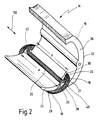
- Fig. 2 is a half of that shown in Fig. 1, in Axial direction divided stator 14 shown in perspective, the dimensions are not absolutely to scale, so that any differences between Fig. 1 and Fig. 2 are not intended but only a consequence of the different presentation types are.
- a pole 22 around which the one leg 18 of the field winding is guided, and the other pole piece 24, about the one leg 21 of the interpolation coil and the second leg 19 of the field winding out is inside out.
- the rotor 12 facing surfaces the pole horns 22, 24 are in a known manner the circular shape of Rotor 12 adapted to the air gap losses as low as possible to keep.
- the pole piece 24 is now the turn pole winding and the field winding each with a leg 21 and 19 are guided, shortened in the axial direction 50, as can be seen in particular from the illustration in FIG. 3, a plan view of one half of the stator of FIG. 2 of above shows.
- the length a is, the pole piece 24, around which the one leg 21 of the interpolation coil and the one leg 19 of the Field winding are guided, a smaller axial length b on.
- the Length b is now such that the interpolation coil 20, 21 with their axial ends 40, 41 each around the end of the pole piece 24 can be guided around without the axial ends 40, 41 beyond the end faces 36 of the laminated stator core 16 also protrude.
- the Wendepolwicklung 20, 21 is thus with their axial ends so approximately flush within the stator lamination 16 recorded or stands slightly outward, there the field winding runs anyway in a radius and not exactly at the end faces.
- the teaching of the invention can be advantageous in series-wound motors use different design, such as the engine according to the above-mentioned EP 0 471 038 B1 or in the engine according to German Patent Application 196 51 298.0, however not pre-published.
- the first mentioned engine acts it is a commutator motor in series with Wendepolen, and with switching devices for switching between Engine and brake operation, wherein in braking mode, the engine by means of the switching device short-circuited and the field winding is reversed, and means for limiting the braking current through the field winding, with which in AC operation a gentle and fast short-circuit braking by independent Self-excitation can be carried out.
- the series motor at least one peeled in series with an armature winding Field winding and at least one intermeshing coil for Braking of the engine in braking mode, as well as a switching device for switching the engine between braking mode and Motor operation.
- the at least one brake winding is in one arranged separate rung, which is activated only in braking mode is.
- the separate current path is via the switching device switched either in braking mode parallel to the armature winding or in braking mode via the switching device coupled in shunt to the supply voltage.
- FIG. 4 A variant of the embodiment according to FIGS. 2 and 3 is shown in FIG. 4 shown.
- FIG. 4 shows a plan view of one half of the stator according to FIG Fig. 2 from above, wherein the pole piece 24a something compared to the pole piece 24 is modified according to FIG. 3.
- the polhorn is 24a shortened at its two ends, as by the length b is indicated.
- the stator lamination 16a at the two axial ends completed by sheets whose cross-section is completely the Corresponds to sheet metal cross section in the middle region, in which no Recesses 42a and 43a are provided, through which the ends the Wendepolwicklung 20a, 21a transverse.
- the pole piece 24a thus has a central region 44a of the Length b on, at both axial ends through the recess 42a and 43a in the form of a transverse groove of one end region 46a and 48a is separated, whose cross section is the cross section of the pole piece 24a in the central region 44a corresponds.
- the pole piece 24a is merely at its two ends interrupted by transverse grooves.
- the reversing pole winding 20a, 21a is as in the embodiment 2 with their legs 20a and 21a in the in Axial direction extending grooves and runs with their axial Ends through the recesses 42a and 43a, which are transverse grooves are executed.
Landscapes
- Engineering & Computer Science (AREA)
- Power Engineering (AREA)
- Iron Core Of Rotating Electric Machines (AREA)
- Dc Machiner (AREA)
- Windings For Motors And Generators (AREA)
- Synchronous Machinery (AREA)
Description
- Fig. 1
- einen Teilquerschnitt durch einen erfindungsgemäßen Motor;
- Fig. 2
- eine perspektivische Ansicht einer Hälfte eines in Längsrichtung geteilten Statorblechpaketes mit je einer eingelegten Wendepolwicklung und Feldwicklung;
- Fig. 3
- eine Aufsicht auf den Stator gemäß Fig. 2 im Bereich der eingelegten Wendepolwicklung, jedoch ohne Feldwicklung; und
- Fig. 4
- eine Aufsicht auf den Stator gemäß Fig. 2 im Bereich der eingelegten Wendepolwicklung, jedoch in einer leicht gegenüber Fig. 2 abgewandelten Ausführung.
Claims (5)
- Reihenschlußmotor mit Kommutator und Wendepolwicklung, insbesondere für ein gebremstes Elektrowerkzeug mit Universalmotor, mit einem Stator (14), der ein Statorblechpaket (16; 16a) aufweist, das ein geschlossenes Joch (32) bildet, mit mindestens zwei Feldwicklungen (18, 19) und mindestens einer Wendepolwicklung (20, 21; 20a, 21a), die in Nuten (26, 28, 30) des Statorblechpaketes (16; 16a) eingelegt ist, dadurch gekennzeichnet, daß das Statorblechpaket (16; 16a) im Bereich der axialen Enden (40, 41) der mindestens einen Wendepolwicklung (20, 21; 20a, 21a) quer zur Axialrichtung (50) des Stators (14) verlaufende Aussparungen (42; 42a, 43a) zur Aufnahme der Wicklungsenden der mindestens einen Wendepolwicklung (20, 21; 20a, 21a) aufweist.
- Reihenschlußmotor nach Anspruch 1, dadurch gekennzeichnet, daß die Aussparungen (42; 42a, 43a) derart ausgebildet sind, daß die axialen Enden (40, 41) der Wendepolwicklung (20, 21; 20a, 21a) nicht oder nur unwesentlich über die Stirnflächen (36; 36a) des Statorblechpaketes (16, 16a) hervorstehen.
- Reihenschlußmotor nach Anspruch 1 oder 2, dadurch gekennzeichnet, daß die Wendepolwicklung (20, 21) um ein Polhorn (24) geführt ist, daß an seinen beiden axialen Enden verkürzt ist.
- Reihenschlußmotor nach einem der vorhergehenden Ansprüche, dadurch gekennzeichnet, daß das Statorblechpaket an seinen beiden Stirnflächen (36a) durch Bleche abgeschlossen ist, deren Querschnitt dem Querschnitt der übrigen Bleche ohne Aussparungen (42a, 42b) entspricht.
- Reihenschlußmotor nach einem der vorhergehenden Ansprüche, dadurch gekennzeichnet, daß die Wendepolwicklung (20, 21; 20a, 21a) mit einem Wicklungsschenkel (20; 20a) in eine Nut (26) zwischen beiden Polhörnern (22, 24) eines Pols (34) eingelegt ist und mit ihrem anderen Wicklungsschenkel (21; 21a) in eine zwischen einem Polhorn und dem Joch (32) gebildete Nut (30) eingelegt ist, wobei die Feldwicklung (18, 19) dieses Pols (34) mit einem Wicklungsschenkel (19) über dem Wicklungsschenkel (21; 21a) der Wendepolwicklung (20, 21; 20a, 21a) verläuft.
Applications Claiming Priority (2)
| Application Number | Priority Date | Filing Date | Title |
|---|---|---|---|
| DE19734958A DE19734958A1 (de) | 1997-08-13 | 1997-08-13 | Reihenschlußmotor |
| DE19734958 | 1997-08-13 |
Publications (3)
| Publication Number | Publication Date |
|---|---|
| EP0897212A2 EP0897212A2 (de) | 1999-02-17 |
| EP0897212A3 EP0897212A3 (de) | 2000-05-10 |
| EP0897212B1 true EP0897212B1 (de) | 2005-01-12 |
Family
ID=7838773
Family Applications (1)
| Application Number | Title | Priority Date | Filing Date |
|---|---|---|---|
| EP98113613A Expired - Lifetime EP0897212B1 (de) | 1997-08-13 | 1998-07-21 | Reihenschlussmotor |
Country Status (5)
| Country | Link |
|---|---|
| US (1) | US6013964A (de) |
| EP (1) | EP0897212B1 (de) |
| JP (1) | JP3541925B2 (de) |
| DE (2) | DE19734958A1 (de) |
| ES (1) | ES2235275T3 (de) |
Families Citing this family (6)
| Publication number | Priority date | Publication date | Assignee | Title |
|---|---|---|---|---|
| WO2002089291A2 (de) * | 2001-04-30 | 2002-11-07 | Schwericke-Radobersky, Ute | Elektrische synchronmaschine mit toroidaler wicklung |
| US6759822B2 (en) * | 2001-12-20 | 2004-07-06 | Southern Illinois University | Methods and apparatus to improve the performance of universal electric motors |
| JP4466098B2 (ja) * | 2004-02-03 | 2010-05-26 | 日立工機株式会社 | 電動モータ、それを備える電動工具及び電動モータの製造方法 |
| JP4901844B2 (ja) * | 2008-11-28 | 2012-03-21 | 三菱電機株式会社 | 整流子電動機及び送風機及び電気掃除機 |
| US20140265680A1 (en) * | 2013-03-15 | 2014-09-18 | Remy Technologies, Llc | Starter |
| US11894754B2 (en) | 2021-03-30 | 2024-02-06 | Milwaukee Electric Tool Corporation | Power tool including universal motor having interpoles |
Family Cites Families (16)
| Publication number | Priority date | Publication date | Assignee | Title |
|---|---|---|---|---|
| CH313036A (de) * | 1951-01-29 | 1956-03-15 | Neuenschwander Otto | Einphasen-Wechselstrom-Spaltpolmotor |
| JPS46217A (de) * | 1970-01-21 | 1971-08-20 | ||
| US3725707A (en) * | 1971-05-05 | 1973-04-03 | Black & Decker Mfg Co | Field sub-assembly for universal electric motors |
| US4058746A (en) * | 1973-01-29 | 1977-11-15 | Westinghouse Electric Corporation | Dynamoelectric machinery utilizing superconductive windings |
| US4041338A (en) * | 1975-11-20 | 1977-08-09 | General Motors Corporation | Direct current dynamoelectric machine commutating pole assembly |
| DK386478A (da) * | 1977-09-19 | 1979-03-20 | Siemens Ag | Elektrisk tomotorsdrivmekanisme |
| JPS5850508B2 (ja) * | 1978-07-31 | 1983-11-10 | ファナック株式会社 | 直流電動機 |
| US4305027A (en) * | 1979-03-14 | 1981-12-08 | Wilson John T R | Multiple windings electrical machines |
| DE2966032D1 (en) * | 1979-11-23 | 1983-09-08 | Fanuc Ltd | Direct current motor |
| US4616150A (en) * | 1985-01-28 | 1986-10-07 | General Motors Corporation | Interpole assembly for a DC machine |
| DE4025713A1 (de) * | 1989-09-06 | 1991-02-21 | Hans Hermann Rottmerhusen | Stromwendermotor |
| DE3929556A1 (de) * | 1989-09-06 | 1990-02-22 | Hans Hermann Rottmerhusen | Stromwendermotor |
| DE4307357A1 (de) * | 1993-03-09 | 1994-09-15 | Bosch Gmbh Robert | Reihenschlußmotor, insbesondere Universalmotor, mit einer Bremseinrichtung |
| US5677586A (en) * | 1994-08-25 | 1997-10-14 | Emerson Electric Co. | Commutation of a universal motor operating in brake mode |
| DE19700074A1 (de) * | 1996-03-22 | 1997-09-25 | Hans Hermann Rottmerhusen | Drehrichtungsumkehrbarer Universalmotor |
| DE19651298C2 (de) * | 1996-12-10 | 1999-04-01 | Fein C & E | Reihenschlußmotor mit Kommutator und Bremswicklung |
-
1997
- 1997-08-13 DE DE19734958A patent/DE19734958A1/de not_active Ceased
-
1998
- 1998-07-21 ES ES98113613T patent/ES2235275T3/es not_active Expired - Lifetime
- 1998-07-21 DE DE59812481T patent/DE59812481D1/de not_active Expired - Lifetime
- 1998-07-21 EP EP98113613A patent/EP0897212B1/de not_active Expired - Lifetime
- 1998-08-03 US US09/128,402 patent/US6013964A/en not_active Expired - Lifetime
- 1998-08-12 JP JP23945398A patent/JP3541925B2/ja not_active Expired - Fee Related
Also Published As
| Publication number | Publication date |
|---|---|
| US6013964A (en) | 2000-01-11 |
| EP0897212A2 (de) | 1999-02-17 |
| DE59812481D1 (de) | 2005-02-17 |
| ES2235275T3 (es) | 2005-07-01 |
| JPH11127566A (ja) | 1999-05-11 |
| EP0897212A3 (de) | 2000-05-10 |
| JP3541925B2 (ja) | 2004-07-14 |
| DE19734958A1 (de) | 1999-02-18 |
Similar Documents
| Publication | Publication Date | Title |
|---|---|---|
| DE102004058046B4 (de) | Hochpolige permanenterregte Synchronmaschine mit Zahnspulen | |
| DE19813155C1 (de) | Mehrsträngige Transversalflußmaschine | |
| EP2054991A1 (de) | Stator für einen elektrischen antriebsmotor | |
| EP1882293A1 (de) | Elektrische maschine mit einem wicklungssystem mit spulengruppen | |
| DE1613671B2 (de) | Einphasen-asynchronmotor | |
| DE102010038764A1 (de) | Wicklungszahn und Komponente für eine elektrische Maschine zur Reduzierung von Wirbelströmen | |
| WO2000005804A1 (de) | Statorbaueinheit für eine elektrische maschine | |
| DE3345672C2 (de) | ||
| DE112006002546B4 (de) | Elektromotor mit asymmetrischen Polen | |
| DE102016211833A1 (de) | Wicklungsträger | |
| EP1997212A1 (de) | Elektrische maschine | |
| EP0897212A2 (de) | Reihenschlussmotor | |
| WO2012150114A2 (de) | Elektromotor | |
| DE102005004380B4 (de) | Linearmotor mit Kraftwelligkeitsausgleich | |
| DE69829652T2 (de) | Stator eines Einphasenelektromotors mit vier parallele Achsen aufweisenden Polen | |
| EP0889575B1 (de) | Elektromotor | |
| DE4411145B4 (de) | Fahrradnabe mit darin angeordnetem Gleichstromgenerator | |
| DE102004054862A1 (de) | Flussmodifizierer für permanenterregten Bürstenmotor unter Verwendung von gewickelten Feldspulen in Kombination mit Permanentmagneten | |
| EP1339158B1 (de) | Reihenschlussmotor | |
| DE1638492A1 (de) | Dynamoelektrische Maschine mit Reluktanzwirkung | |
| DE19824042A1 (de) | Dreiphasengleichstrommotor mit elektronischer Kommutierung und hoher Motorleistung | |
| DE19833021A1 (de) | Statorbaueinheit für eine elektrische Maschine | |
| DE102004058045B4 (de) | Elektrische Maschine mit Zahnspulenwicklung | |
| DE657495C (de) | Stromwendungseinrichtung | |
| DE663697C (de) | Elektrische Kommutatormaschine mit Trommelanker |
Legal Events
| Date | Code | Title | Description |
|---|---|---|---|
| PUAI | Public reference made under article 153(3) epc to a published international application that has entered the european phase |
Free format text: ORIGINAL CODE: 0009012 |
|
| AK | Designated contracting states |
Kind code of ref document: A2 Designated state(s): CH DE ES FR GB IT LI NL SE |
|
| AX | Request for extension of the european patent |
Free format text: AL;LT;LV;MK;RO;SI |
|
| PUAL | Search report despatched |
Free format text: ORIGINAL CODE: 0009013 |
|
| AK | Designated contracting states |
Kind code of ref document: A3 Designated state(s): AT BE CH CY DE DK ES FI FR GB GR IE IT LI LU MC NL PT SE |
|
| AX | Request for extension of the european patent |
Free format text: AL;LT;LV;MK;RO;SI |
|
| RAP1 | Party data changed (applicant data changed or rights of an application transferred) |
Owner name: C. & E. FEIN GMBH & CO. KG |
|
| 17P | Request for examination filed |
Effective date: 20001102 |
|
| AKX | Designation fees paid |
Free format text: CH DE ES FR GB IT LI NL SE |
|
| RAP1 | Party data changed (applicant data changed or rights of an application transferred) |
Owner name: C. & E. FEIN GMBH |
|
| GRAP | Despatch of communication of intention to grant a patent |
Free format text: ORIGINAL CODE: EPIDOSNIGR1 |
|
| GRAS | Grant fee paid |
Free format text: ORIGINAL CODE: EPIDOSNIGR3 |
|
| RAP1 | Party data changed (applicant data changed or rights of an application transferred) |
Owner name: C. & E. FEIN GMBH |
|
| GRAA | (expected) grant |
Free format text: ORIGINAL CODE: 0009210 |
|
| AK | Designated contracting states |
Kind code of ref document: B1 Designated state(s): CH DE ES FR GB IT LI NL SE |
|
| REG | Reference to a national code |
Ref country code: GB Ref legal event code: FG4D Free format text: NOT ENGLISH |
|
| REG | Reference to a national code |
Ref country code: CH Ref legal event code: NV Representative=s name: TROESCH SCHEIDEGGER WERNER AG Ref country code: CH Ref legal event code: EP |
|
| REG | Reference to a national code |
Ref country code: SE Ref legal event code: TRGR |
|
| GBT | Gb: translation of ep patent filed (gb section 77(6)(a)/1977) |
Effective date: 20050125 |
|
| REF | Corresponds to: |
Ref document number: 59812481 Country of ref document: DE Date of ref document: 20050217 Kind code of ref document: P |
|
| REG | Reference to a national code |
Ref country code: ES Ref legal event code: FG2A Ref document number: 2235275 Country of ref document: ES Kind code of ref document: T3 |
|
| PLBE | No opposition filed within time limit |
Free format text: ORIGINAL CODE: 0009261 |
|
| STAA | Information on the status of an ep patent application or granted ep patent |
Free format text: STATUS: NO OPPOSITION FILED WITHIN TIME LIMIT |
|
| ET | Fr: translation filed | ||
| 26N | No opposition filed |
Effective date: 20051013 |
|
| PGFP | Annual fee paid to national office [announced via postgrant information from national office to epo] |
Ref country code: CH Payment date: 20110712 Year of fee payment: 14 |
|
| PGFP | Annual fee paid to national office [announced via postgrant information from national office to epo] |
Ref country code: GB Payment date: 20120718 Year of fee payment: 15 Ref country code: SE Payment date: 20120711 Year of fee payment: 15 |
|
| PGFP | Annual fee paid to national office [announced via postgrant information from national office to epo] |
Ref country code: IT Payment date: 20120718 Year of fee payment: 15 Ref country code: FR Payment date: 20120719 Year of fee payment: 15 Ref country code: ES Payment date: 20120824 Year of fee payment: 15 |
|
| PGFP | Annual fee paid to national office [announced via postgrant information from national office to epo] |
Ref country code: NL Payment date: 20120710 Year of fee payment: 15 |
|
| REG | Reference to a national code |
Ref country code: NL Ref legal event code: V1 Effective date: 20140201 |
|
| REG | Reference to a national code |
Ref country code: CH Ref legal event code: PL |
|
| REG | Reference to a national code |
Ref country code: SE Ref legal event code: EUG |
|
| GBPC | Gb: european patent ceased through non-payment of renewal fee |
Effective date: 20130721 |
|
| REG | Reference to a national code |
Ref country code: FR Ref legal event code: ST Effective date: 20140331 |
|
| PG25 | Lapsed in a contracting state [announced via postgrant information from national office to epo] |
Ref country code: SE Free format text: LAPSE BECAUSE OF NON-PAYMENT OF DUE FEES Effective date: 20130722 Ref country code: NL Free format text: LAPSE BECAUSE OF NON-PAYMENT OF DUE FEES Effective date: 20140201 Ref country code: CH Free format text: LAPSE BECAUSE OF NON-PAYMENT OF DUE FEES Effective date: 20130731 Ref country code: LI Free format text: LAPSE BECAUSE OF NON-PAYMENT OF DUE FEES Effective date: 20130731 Ref country code: GB Free format text: LAPSE BECAUSE OF NON-PAYMENT OF DUE FEES Effective date: 20130721 |
|
| PG25 | Lapsed in a contracting state [announced via postgrant information from national office to epo] |
Ref country code: FR Free format text: LAPSE BECAUSE OF NON-PAYMENT OF DUE FEES Effective date: 20130731 Ref country code: IT Free format text: LAPSE BECAUSE OF NON-PAYMENT OF DUE FEES Effective date: 20130721 |
|
| REG | Reference to a national code |
Ref country code: ES Ref legal event code: FD2A Effective date: 20140905 |
|
| PG25 | Lapsed in a contracting state [announced via postgrant information from national office to epo] |
Ref country code: ES Free format text: LAPSE BECAUSE OF NON-PAYMENT OF DUE FEES Effective date: 20130722 |
|
| PGFP | Annual fee paid to national office [announced via postgrant information from national office to epo] |
Ref country code: DE Payment date: 20150714 Year of fee payment: 18 |
|
| REG | Reference to a national code |
Ref country code: DE Ref legal event code: R119 Ref document number: 59812481 Country of ref document: DE |
|
| PG25 | Lapsed in a contracting state [announced via postgrant information from national office to epo] |
Ref country code: DE Free format text: LAPSE BECAUSE OF NON-PAYMENT OF DUE FEES Effective date: 20170201 |