EP0897108B1 - Verfahren und Vorrichtung zum analytischen Nachweis von Spuren - Google Patents
Verfahren und Vorrichtung zum analytischen Nachweis von Spuren Download PDFInfo
- Publication number
- EP0897108B1 EP0897108B1 EP98111821A EP98111821A EP0897108B1 EP 0897108 B1 EP0897108 B1 EP 0897108B1 EP 98111821 A EP98111821 A EP 98111821A EP 98111821 A EP98111821 A EP 98111821A EP 0897108 B1 EP0897108 B1 EP 0897108B1
- Authority
- EP
- European Patent Office
- Prior art keywords
- capillary
- sample
- detection device
- desorption chamber
- light
- Prior art date
- Legal status (The legal status is an assumption and is not a legal conclusion. Google has not performed a legal analysis and makes no representation as to the accuracy of the status listed.)
- Expired - Lifetime
Links
Images

Classifications
-
- G—PHYSICS
- G01—MEASURING; TESTING
- G01N—INVESTIGATING OR ANALYSING MATERIALS BY DETERMINING THEIR CHEMICAL OR PHYSICAL PROPERTIES
- G01N1/00—Sampling; Preparing specimens for investigation
- G01N1/28—Preparing specimens for investigation including physical details of (bio-)chemical methods covered elsewhere, e.g. G01N33/50, C12Q
- G01N1/40—Concentrating samples
- G01N1/4022—Concentrating samples by thermal techniques; Phase changes
-
- G—PHYSICS
- G01—MEASURING; TESTING
- G01N—INVESTIGATING OR ANALYSING MATERIALS BY DETERMINING THEIR CHEMICAL OR PHYSICAL PROPERTIES
- G01N1/00—Sampling; Preparing specimens for investigation
- G01N1/28—Preparing specimens for investigation including physical details of (bio-)chemical methods covered elsewhere, e.g. G01N33/50, C12Q
- G01N1/40—Concentrating samples
- G01N1/405—Concentrating samples by adsorption or absorption
-
- G—PHYSICS
- G01—MEASURING; TESTING
- G01N—INVESTIGATING OR ANALYSING MATERIALS BY DETERMINING THEIR CHEMICAL OR PHYSICAL PROPERTIES
- G01N1/00—Sampling; Preparing specimens for investigation
- G01N1/02—Devices for withdrawing samples
- G01N2001/022—Devices for withdrawing samples sampling for security purposes, e.g. contraband, warfare agents
-
- G—PHYSICS
- G01—MEASURING; TESTING
- G01N—INVESTIGATING OR ANALYSING MATERIALS BY DETERMINING THEIR CHEMICAL OR PHYSICAL PROPERTIES
- G01N1/00—Sampling; Preparing specimens for investigation
- G01N1/02—Devices for withdrawing samples
- G01N2001/028—Sampling from a surface, swabbing, vaporising
-
- G—PHYSICS
- G01—MEASURING; TESTING
- G01N—INVESTIGATING OR ANALYSING MATERIALS BY DETERMINING THEIR CHEMICAL OR PHYSICAL PROPERTIES
- G01N1/00—Sampling; Preparing specimens for investigation
- G01N1/02—Devices for withdrawing samples
- G01N1/04—Devices for withdrawing samples in the solid state, e.g. by cutting
- G01N2001/045—Laser ablation; Microwave vaporisation
Definitions
- the invention relates to a method and a device for analytical detection of tracks.
- IMS Ion drift spectrometer
- mass spectrometer known as a sensitive analytical method for certain organics.
- Baim, M.A .; Eatherton, R. L .; Hill, H.H. Jr .; Anal. Chem. 1983, 55, 1761-1766 the use of an IMS device as a detector for a gas chromatograph (GC), where the capillary of the GC device has been connected to the IMS device.
- GC gas chromatograph
- From US 5,663,561 is a method for ionizing heavy molecules at atmospheric pressure known to be sucked in the decomposition products via a capillary.
- the object of the invention is a method and a device for spatially resolved To provide trace analysis.
- the device with the capillaries is at least 10 to 100 times more sensitive.
- the capillary also provides a very sensitive "nose" for monitoring the room air in relation on dangerous substances. For multipoint measurements it is through the use of a capillary possible to increase the polling rate.
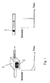
- Fig. 1 shows the top left of a transport line which widened by a transport volume is and next to a simple transport line. Below are the corresponding time-dependent ones Detector signals shown.
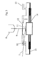
- a laser is used as the light source 4.
- the laser beam 9 is over the deflecting mirror 5 coupled into a microscope 6 and the sample 11 (not shown here) focused.
- the sample 1 is in the desorption chamber 7.
- the desorbed gas sample 2 passes through the capillary 1 into the detection device 8.
- the construction of the laser desorption chamber completely dispenses with organic lubricants or sealing materials such as silicones or rubber. Nevertheless, the sample can be positioned with the help of the laser desorption in any inert gas atmosphere under a microscope objective that can be organic compounds on an area of about 50 microns 2 desorb with a laser beam at room temperature.
- the released organic molecules can be led out with the capillaries 1 from the laser desorption chamber 7 and transported to an analysis device such as the IMS device.
- the capillary passage 10 consists of a centric pierced ball of insulating material, which sits positively on the capillaries 1.
- the Seal of the ball in the desorption chamber 7 is by a ball joint and a metal ring or Teflon ring sealed without restricting mobility.
- the capillary 1 is off Glass or quartz. The ability of the capillary 1 depends on the desorbed sample crucial from their distance to the desorption point. Therefore, the capillary 1 should be so close as possible be brought to the desorption without shading the laser beam 9.
- the capillary diameter should be greater than the diameter of the laser spot on the Sample. As favorable, a size ratio of 7 to 1 has proven. With too large proportions (greater than 15) the detection sensitivity decreases. Should polar substances be detected can be their adsorption in the capillary both by heating and by special deactivations e.g. be reduced with silanes.
- the heating of the capillaries will characterized in that the glass capillary is surrounded by a metal tube or that a Metal capillary inside is coated with quartz. The metal layer is over in both cases heated their resistance.
- the power supply lines are not shown here.
- the laser desorption chamber 7 is inserted into a microscope stage which is in the x, y and z axes is adjustable.
- the movement of the microscope stage in the x and y direction is on a sample carriage 14 made of brass, in the center of a downwardly removable sample holder (not shown here) sits.
- a sample can be compared to the sample holder the top of the desorption chamber (made of Al) and the lens of the microscope up to exactly one ⁇ m.
- the aluminum hood over 2 retaining pins, a retaining plate and 2 feet screwed to the table on which the microscope is mounted. This allows the Laser desorption chamber relative to the lens can only be moved in the z-direction to the focus adjust.
- the movable sample carriage 14 To seal the interior of the desorption chamber 7 against the laboratory air, is the movable sample carriage 14 with two annular plates to the rinschlisch slide guide 15 pressed from V2A.
- the lower annular plate of the sample carriage 14 is removable and fixed so that the play of the lapped plates is 10 to 20 ⁇ m.
- Lubricants can seriously affect the measurement results, all the game fits so be interpreted that they have sufficient lubricity even without lubricants.
- the laser beam coupled into the microscope passes through a glass disc into the laser desorption chamber, where it meets the sample lying on the sample holder.
- any organics present are desorbed by the energy of the laser beam, usually undestroyed, from the surface of the sample.
- the window 12 is screwed without sealing rubber, silicone or the like only brass fasteners with an external thread in the upper part. Although this does not give a gas-tight chamber, it can generate an overpressure of about 4 mbar in the laser desorption chamber via the gas inlet 13 and a gas flow of 400 ml / min, which largely prevents the penetration of laboratory air.
- the internal pressure is sufficient to transport the laser-sorbed substance mixed with the gas in the interior with a volume flow of about 4 ml / min via a heated line in the IMS device.
- the largest possible volume flow through the capillary is advantageous. This shortens the time in which the gas sample 2 interacts with the capillaries.
- the dead time required for the substance to be transported through the capillary decreases and it is possible to start irradiation sooner and thus desorption of the next site.
- IMS spectra with a spatial resolution of approximately 50 ⁇ m 2 are more meaningful than without a laser desorption chamber.
- the desorbed Substance can be pressed into the IMS device, due to the leaky drift cell of the IMS device leads to less contamination in the IMS spectrum, than the suction at the gas outlet of the IMS device.
- the desorbed Substance can be squeezed into each meter, if this brings an advantage.
- Minimum distance between lens and sample holder is 6.8 mm, which is for a lens with extra large working distance and 1000x magnification is sufficient.
- An advantage is the coupling of an ion drift spectrometer (IMS) or ionic drift spectrometer followed by mass spectrograph (IMS / MS) as a detector to a unit using the of a laser substances of a sample surface desorbed spatially resolved and in the analyzer transferred.
- IMS ion drift spectrometer
- MS mass spectrograph
- a laser beam acts on the surface to be analyzed and desorbs all organic compounds over an area of approximately 50 ⁇ m 2 .
- the molecules thus released are taken up by a transport medium, transported to the IMS device as a sensitive detector for certain organics and detected there. It is possible to determine the composition on different parts of a surface and thus to make statements about the origin of the differences. This can z. B. the failures of electronic components (on wafers) are explained. As a result, the process can be optimized.
- the neutral molecules that were vaporized were taken up by a transport unit, in this case a heated capillary, and transferred to the IMS device, where the detection of the incoming molecules took place.
- IMS spectra were continuously collected every 7 seconds to record the time course of the signal intensity of the molecules arriving at the IMS device.
- the method is suitable for most carrier materials, such as e.g. Wafer or metals non-destructive.
- the matrix in which the substance to be analyzed sits can thus largely hidden be that only one conspicuous spot is irradiated with the laser, while the surrounding matrix stays cold.
- the method depends on how well the individual substances with the used Extract solvent.
- a laser beam acts on the surface to be analyzed, desorbing all organic compounds over an area of about 10-100 ⁇ m 2 .
- the molecules thus released are taken up by a capillary placed in the immediate vicinity and heated and transported into the analyzer.
- the laser desorption is faster than the extraction, resulting in a higher sample throughput ever Time unit and thus leads to a cost savings.
- the matrix in which the substance to be analyzed sits can thus largely hidden be that only one conspicuous spot is irradiated with the laser, while the surrounding matrix stays cold.
- GC gas chromatographs
- IMS ionic drift spectrometer
Landscapes
- Physics & Mathematics (AREA)
- Health & Medical Sciences (AREA)
- Life Sciences & Earth Sciences (AREA)
- Chemical & Material Sciences (AREA)
- Analytical Chemistry (AREA)
- Biochemistry (AREA)
- General Health & Medical Sciences (AREA)
- General Physics & Mathematics (AREA)
- Immunology (AREA)
- Pathology (AREA)
- Other Investigation Or Analysis Of Materials By Electrical Means (AREA)
- Sampling And Sample Adjustment (AREA)
- Investigating, Analyzing Materials By Fluorescence Or Luminescence (AREA)
- Analysing Materials By The Use Of Radiation (AREA)
Applications Claiming Priority (2)
| Application Number | Priority Date | Filing Date | Title |
|---|---|---|---|
| DE19734460A DE19734460A1 (de) | 1997-08-11 | 1997-08-11 | Verfahren und Vorrichtung zum analytischen Nachweis von Spuren |
| DE19734460 | 1997-08-11 |
Publications (2)
| Publication Number | Publication Date |
|---|---|
| EP0897108A1 EP0897108A1 (de) | 1999-02-17 |
| EP0897108B1 true EP0897108B1 (de) | 2005-08-17 |
Family
ID=7838449
Family Applications (1)
| Application Number | Title | Priority Date | Filing Date |
|---|---|---|---|
| EP98111821A Expired - Lifetime EP0897108B1 (de) | 1997-08-11 | 1998-06-26 | Verfahren und Vorrichtung zum analytischen Nachweis von Spuren |
Country Status (5)
| Country | Link |
|---|---|
| US (1) | US6084237A (OSRAM) |
| EP (1) | EP0897108B1 (OSRAM) |
| JP (1) | JPH11118780A (OSRAM) |
| AT (1) | ATE302406T1 (OSRAM) |
| DE (2) | DE19734460A1 (OSRAM) |
Families Citing this family (7)
| Publication number | Priority date | Publication date | Assignee | Title |
|---|---|---|---|---|
| US7473401B1 (en) * | 1997-12-04 | 2009-01-06 | Mds Analytical Technologies (Us) Inc. | Fluidic extraction of microdissected samples |
| DE19913451C2 (de) * | 1999-03-25 | 2001-11-22 | Gsf Forschungszentrum Umwelt | Gaseinlaß zur Erzeugung eines gerichteten und gekühlten Gasstrahls |
| US6495825B1 (en) * | 1999-12-22 | 2002-12-17 | International Business Machines Corporation | Apparatus for photo exposure of materials with subsequent capturing of volatiles for analysis |
| EP1279020B1 (en) * | 2000-04-26 | 2016-03-16 | Life Technologies Corporation | Laser capture microdissection (lcm) extraction device and device carrier and method for post-lcm fluid processing |
| DE102015107342B4 (de) * | 2015-05-11 | 2017-01-19 | Airbus Defence and Space GmbH | Oberflächenuntersuchung von Bauteilen |
| DE102015107341B3 (de) * | 2015-05-11 | 2016-09-22 | Airbus Defence and Space GmbH | Vorrichtung und Verfahren zum Untersuchen von Schichtmaterial auf Verunreinigung |
| GB2571565B (en) * | 2018-03-01 | 2021-05-26 | Thermo Fisher Scient Bremen Gmbh | Inert non-adsorbing crimpable capillaries and devices for adjusting gas flow in isotope ratio analysis |
Family Cites Families (8)
| Publication number | Priority date | Publication date | Assignee | Title |
|---|---|---|---|---|
| US4970905A (en) * | 1989-05-25 | 1990-11-20 | University Of Utah | Apparatus and method for sampling |
| US4977320A (en) * | 1990-01-22 | 1990-12-11 | The Rockefeller University | Electrospray ionization mass spectrometer with new features |
| US5210412A (en) * | 1991-01-31 | 1993-05-11 | Wayne State University | Method for analyzing an organic sample |
| DE4108462C2 (de) * | 1991-03-13 | 1994-10-13 | Bruker Franzen Analytik Gmbh | Verfahren und Vorrichtung zum Erzeugen von Ionen aus thermisch instabilen, nichtflüchtigen großen Molekülen |
| CA2101237C (en) * | 1992-09-11 | 1999-04-13 | Stephen Ward Downey | Apparatus comprising means for mass spectrometry |
| DE19608963C2 (de) * | 1995-03-28 | 2001-03-22 | Bruker Daltonik Gmbh | Verfahren zur Ionisierung schwerer Moleküle bei Atmosphärendruck |
| GB2300257B (en) * | 1995-04-28 | 1999-08-25 | Deutsche Forsch Luft Raumfahrt | Method and device for determination of the albedo of particles |
| US5742050A (en) * | 1996-09-30 | 1998-04-21 | Aviv Amirav | Method and apparatus for sample introduction into a mass spectrometer for improving a sample analysis |
-
1997
- 1997-08-11 DE DE19734460A patent/DE19734460A1/de not_active Ceased
-
1998
- 1998-06-26 EP EP98111821A patent/EP0897108B1/de not_active Expired - Lifetime
- 1998-06-26 DE DE59813004T patent/DE59813004D1/de not_active Expired - Lifetime
- 1998-06-26 AT AT98111821T patent/ATE302406T1/de not_active IP Right Cessation
- 1998-08-07 JP JP22461298A patent/JPH11118780A/ja active Pending
- 1998-08-10 US US09/131,465 patent/US6084237A/en not_active Expired - Fee Related
Also Published As
| Publication number | Publication date |
|---|---|
| EP0897108A1 (de) | 1999-02-17 |
| DE19734460A1 (de) | 1999-02-18 |
| US6084237A (en) | 2000-07-04 |
| ATE302406T1 (de) | 2005-09-15 |
| JPH11118780A (ja) | 1999-04-30 |
| DE59813004D1 (de) | 2005-09-22 |
Similar Documents
| Publication | Publication Date | Title |
|---|---|---|
| DE69718811T2 (de) | Verfahren zur schnellen in-situ analyse ausgewählter bestandteile von homogenen festen zusammensetzungen, insbesondere pharmazeutischen zusammensetzungen | |
| DE3789182T2 (de) | Sonde für Elektrophorese-Massenspektrometrie. | |
| DE69029517T2 (de) | Vorrichtung und verfahren zur probenentnahme | |
| US20040045497A1 (en) | Analysis method for detecting three-dimensional trace element distribution patterns and corresponding device for carrying out this method | |
| CH616275A5 (OSRAM) | ||
| WO2010115394A1 (de) | Verfahren und vorrichtung zur durchführung einer quantitativen ortsaufgelösten lokal- und verteilungsanalyse chemischer elemente und in-situ charakterisierung de ablatierten oberflächenregionen | |
| EP1697736B1 (de) | Vorrichtung zur probenvorbereitung | |
| EP0897108B1 (de) | Verfahren und Vorrichtung zum analytischen Nachweis von Spuren | |
| DE2363775B2 (de) | Gerät zur Untersuchung mikroskopischer Objekte durch Pyrolyse | |
| EP0448816A2 (de) | Vorrichtung zur Bestimmung flüchtiger Stoffe in einer Flüssigkeit | |
| EP1045242B1 (de) | Verfahren und Vorrichtung zur grössenaufgelösten chemischen und physikalischen Bestimmung von Aerosolpartikeln | |
| EP0577635B1 (de) | Einrichtung zur verdampfung kleiner mengen eines fluids für analytische zwecke | |
| DE102007033906A1 (de) | Verfahren zur Analyse von Gasen, insbesondere zur Analyse der menschlichen Ausatemluft | |
| EP0770870B1 (de) | Ventil und dessen Verwendung | |
| DE19529717A1 (de) | Verfahren und Vorrichtung zur Präparation einer anorganischen oder organischen Probe für die Isotopenverhältnisanalyse | |
| Palmieri | An introduction to supercritical fluid chromatography part 1: principles and instrumentation | |
| DE60226046T2 (de) | Probenentnahmegerät für automatische elementaranalysevorrichtungen | |
| EP0360901A1 (de) | Verfahren und Vorrichtung zur Probennahme und Analyse von Kohlenwasserstoffen | |
| EP1831680B1 (de) | Verfahren zur Elementaranalyse einer organischen Probe, die durch Verbrennung aufgeschlossen wird, und Vorrichtung zur Durchführung des Verfahrens | |
| EP4413609B1 (de) | Vorrichtung zur aufnahme eines feststoff-probenmaterials und system und verfahren mit dieser | |
| DE4133701C2 (de) | Verfahren und Vorrichtung zur spurenanalytischen Konzentrationsbestimmung von sich in einem Trägergas befindenden Molekülen | |
| Elbert et al. | Off-line coupling of liquid chromatograph and mass spectrometer | |
| CH624770A5 (OSRAM) | ||
| Goates et al. | Direct supersonic expansions of supercritical fluids for analysis of polycyclic aromatic hydrocarbons | |
| DE4109858C2 (de) | Verfahren zum Nachweisen von Stoffen, die aus Substanzen emittiert werden |
Legal Events
| Date | Code | Title | Description |
|---|---|---|---|
| PUAI | Public reference made under article 153(3) epc to a published international application that has entered the european phase |
Free format text: ORIGINAL CODE: 0009012 |
|
| AK | Designated contracting states |
Kind code of ref document: A1 Designated state(s): AT BE CH DE DK FI FR GB GR IE IT LI NL SE |
|
| AX | Request for extension of the european patent |
Free format text: AL;LT;LV;MK;RO;SI |
|
| 17P | Request for examination filed |
Effective date: 19990308 |
|
| AKX | Designation fees paid |
Free format text: AT BE CH DE DK FI FR GB GR IE LI |
|
| RBV | Designated contracting states (corrected) |
Designated state(s): AT BE CH DE DK FI FR GB GR IE IT LI NL SE |
|
| 17Q | First examination report despatched |
Effective date: 20021128 |
|
| GRAP | Despatch of communication of intention to grant a patent |
Free format text: ORIGINAL CODE: EPIDOSNIGR1 |
|
| GRAS | Grant fee paid |
Free format text: ORIGINAL CODE: EPIDOSNIGR3 |
|
| GRAA | (expected) grant |
Free format text: ORIGINAL CODE: 0009210 |
|
| RIN1 | Information on inventor provided before grant (corrected) |
Inventor name: KETTRUP, ANTONIUS, PROF. DR. Inventor name: HOLZAPFEL, WINFRIED, DR. Inventor name: TROESTER, KLAUS |
|
| RTI1 | Title (correction) |
Free format text: METHOD AND APPARATUS FOR ANALYTIC DETECTION OF TRACES |
|
| AK | Designated contracting states |
Kind code of ref document: B1 Designated state(s): AT BE CH DE DK FI FR GB GR IE IT LI NL SE |
|
| PG25 | Lapsed in a contracting state [announced via postgrant information from national office to epo] |
Ref country code: NL Free format text: LAPSE BECAUSE OF FAILURE TO SUBMIT A TRANSLATION OF THE DESCRIPTION OR TO PAY THE FEE WITHIN THE PRESCRIBED TIME-LIMIT Effective date: 20050817 Ref country code: IT Free format text: LAPSE BECAUSE OF FAILURE TO SUBMIT A TRANSLATION OF THE DESCRIPTION OR TO PAY THE FEE WITHIN THE PRESCRIBED TIME-LIMIT;WARNING: LAPSES OF ITALIAN PATENTS WITH EFFECTIVE DATE BEFORE 2007 MAY HAVE OCCURRED AT ANY TIME BEFORE 2007. THE CORRECT EFFECTIVE DATE MAY BE DIFFERENT FROM THE ONE RECORDED. Effective date: 20050817 Ref country code: FI Free format text: LAPSE BECAUSE OF FAILURE TO SUBMIT A TRANSLATION OF THE DESCRIPTION OR TO PAY THE FEE WITHIN THE PRESCRIBED TIME-LIMIT Effective date: 20050817 |
|
| REG | Reference to a national code |
Ref country code: GB Ref legal event code: FG4D Free format text: NOT ENGLISH |
|
| REG | Reference to a national code |
Ref country code: CH Ref legal event code: EP |
|
| REG | Reference to a national code |
Ref country code: IE Ref legal event code: FG4D Free format text: LANGUAGE OF EP DOCUMENT: GERMAN |
|
| REF | Corresponds to: |
Ref document number: 59813004 Country of ref document: DE Date of ref document: 20050922 Kind code of ref document: P |
|
| REG | Reference to a national code |
Ref country code: CH Ref legal event code: NV Representative=s name: ROTTMANN, ZIMMERMANN + PARTNER AG |
|
| PG25 | Lapsed in a contracting state [announced via postgrant information from national office to epo] |
Ref country code: SE Free format text: LAPSE BECAUSE OF FAILURE TO SUBMIT A TRANSLATION OF THE DESCRIPTION OR TO PAY THE FEE WITHIN THE PRESCRIBED TIME-LIMIT Effective date: 20051117 Ref country code: GR Free format text: LAPSE BECAUSE OF FAILURE TO SUBMIT A TRANSLATION OF THE DESCRIPTION OR TO PAY THE FEE WITHIN THE PRESCRIBED TIME-LIMIT Effective date: 20051117 Ref country code: DK Free format text: LAPSE BECAUSE OF FAILURE TO SUBMIT A TRANSLATION OF THE DESCRIPTION OR TO PAY THE FEE WITHIN THE PRESCRIBED TIME-LIMIT Effective date: 20051117 |
|
| GBT | Gb: translation of ep patent filed (gb section 77(6)(a)/1977) |
Effective date: 20051111 |
|
| NLV1 | Nl: lapsed or annulled due to failure to fulfill the requirements of art. 29p and 29m of the patents act | ||
| ET | Fr: translation filed | ||
| PLBE | No opposition filed within time limit |
Free format text: ORIGINAL CODE: 0009261 |
|
| STAA | Information on the status of an ep patent application or granted ep patent |
Free format text: STATUS: NO OPPOSITION FILED WITHIN TIME LIMIT |
|
| 26N | No opposition filed |
Effective date: 20060518 |
|
| PGFP | Annual fee paid to national office [announced via postgrant information from national office to epo] |
Ref country code: BE Payment date: 20070615 Year of fee payment: 10 |
|
| PGFP | Annual fee paid to national office [announced via postgrant information from national office to epo] |
Ref country code: IE Payment date: 20070618 Year of fee payment: 10 |
|
| PGFP | Annual fee paid to national office [announced via postgrant information from national office to epo] |
Ref country code: AT Payment date: 20070626 Year of fee payment: 10 |
|
| PGFP | Annual fee paid to national office [announced via postgrant information from national office to epo] |
Ref country code: GB Payment date: 20070608 Year of fee payment: 10 Ref country code: CH Payment date: 20070629 Year of fee payment: 10 |
|
| PGFP | Annual fee paid to national office [announced via postgrant information from national office to epo] |
Ref country code: FR Payment date: 20070628 Year of fee payment: 10 |
|
| BERE | Be: lapsed |
Owner name: *GSF-FORSCHUNGSZENTRUM FUR UMWELT UND GESUNDHEIT G Effective date: 20080630 |
|
| REG | Reference to a national code |
Ref country code: CH Ref legal event code: PL |
|
| GBPC | Gb: european patent ceased through non-payment of renewal fee |
Effective date: 20080626 |
|
| PG25 | Lapsed in a contracting state [announced via postgrant information from national office to epo] |
Ref country code: BE Free format text: LAPSE BECAUSE OF NON-PAYMENT OF DUE FEES Effective date: 20080630 |
|
| REG | Reference to a national code |
Ref country code: IE Ref legal event code: MM4A |
|
| REG | Reference to a national code |
Ref country code: FR Ref legal event code: ST Effective date: 20090228 |
|
| PG25 | Lapsed in a contracting state [announced via postgrant information from national office to epo] |
Ref country code: IE Free format text: LAPSE BECAUSE OF NON-PAYMENT OF DUE FEES Effective date: 20080626 Ref country code: AT Free format text: LAPSE BECAUSE OF NON-PAYMENT OF DUE FEES Effective date: 20080626 |
|
| PG25 | Lapsed in a contracting state [announced via postgrant information from national office to epo] |
Ref country code: LI Free format text: LAPSE BECAUSE OF NON-PAYMENT OF DUE FEES Effective date: 20080630 Ref country code: GB Free format text: LAPSE BECAUSE OF NON-PAYMENT OF DUE FEES Effective date: 20080626 Ref country code: CH Free format text: LAPSE BECAUSE OF NON-PAYMENT OF DUE FEES Effective date: 20080630 |
|
| PG25 | Lapsed in a contracting state [announced via postgrant information from national office to epo] |
Ref country code: FR Free format text: LAPSE BECAUSE OF NON-PAYMENT OF DUE FEES Effective date: 20080630 |
|
| PGFP | Annual fee paid to national office [announced via postgrant information from national office to epo] |
Ref country code: DE Payment date: 20120629 Year of fee payment: 15 |
|
| REG | Reference to a national code |
Ref country code: DE Ref legal event code: R119 Ref document number: 59813004 Country of ref document: DE Effective date: 20140101 |
|
| PG25 | Lapsed in a contracting state [announced via postgrant information from national office to epo] |
Ref country code: DE Free format text: LAPSE BECAUSE OF NON-PAYMENT OF DUE FEES Effective date: 20140101 |