EP0897099B1 - Ultraschalldickenmessgerät für Mehrschichtstrukturen - Google Patents
Ultraschalldickenmessgerät für Mehrschichtstrukturen Download PDFInfo
- Publication number
- EP0897099B1 EP0897099B1 EP98115026A EP98115026A EP0897099B1 EP 0897099 B1 EP0897099 B1 EP 0897099B1 EP 98115026 A EP98115026 A EP 98115026A EP 98115026 A EP98115026 A EP 98115026A EP 0897099 B1 EP0897099 B1 EP 0897099B1
- Authority
- EP
- European Patent Office
- Prior art keywords
- layer
- peak
- interface
- vapor barrier
- pulse
- Prior art date
- Legal status (The legal status is an assumption and is not a legal conclusion. Google has not performed a legal analysis and makes no representation as to the accuracy of the status listed.)
- Expired - Lifetime
Links
- 238000009683 ultrasonic thickness measurement Methods 0.000 title 1
- 239000010410 layer Substances 0.000 claims description 162
- 239000002828 fuel tank Substances 0.000 claims description 58
- 239000000463 material Substances 0.000 claims description 37
- 230000004888 barrier function Effects 0.000 claims description 34
- 239000012790 adhesive layer Substances 0.000 claims description 33
- 238000000034 method Methods 0.000 claims description 31
- 229920003023 plastic Polymers 0.000 claims description 25
- 239000004033 plastic Substances 0.000 claims description 25
- 230000000875 corresponding effect Effects 0.000 claims description 17
- 230000005540 biological transmission Effects 0.000 claims description 14
- 238000005070 sampling Methods 0.000 claims description 4
- 230000008859 change Effects 0.000 claims description 3
- 238000010276 construction Methods 0.000 claims description 3
- 230000002596 correlated effect Effects 0.000 claims description 3
- 238000006073 displacement reaction Methods 0.000 claims 1
- 229920001903 high density polyethylene Polymers 0.000 description 15
- 239000004700 high-density polyethylene Substances 0.000 description 15
- 238000004519 manufacturing process Methods 0.000 description 11
- 238000007654 immersion Methods 0.000 description 5
- 239000011347 resin Substances 0.000 description 5
- 229920005989 resin Polymers 0.000 description 5
- 239000004698 Polyethylene Substances 0.000 description 4
- 238000004364 calculation method Methods 0.000 description 4
- 239000004715 ethylene vinyl alcohol Substances 0.000 description 4
- 229930195733 hydrocarbon Natural products 0.000 description 4
- 150000002430 hydrocarbons Chemical class 0.000 description 4
- -1 polyethylene Polymers 0.000 description 4
- 229920000573 polyethylene Polymers 0.000 description 4
- 238000012360 testing method Methods 0.000 description 4
- 239000004215 Carbon black (E152) Substances 0.000 description 3
- 229920000219 Ethylene vinyl alcohol Polymers 0.000 description 3
- 230000001066 destructive effect Effects 0.000 description 3
- RZXDTJIXPSCHCI-UHFFFAOYSA-N hexa-1,5-diene-2,5-diol Chemical compound OC(=C)CCC(O)=C RZXDTJIXPSCHCI-UHFFFAOYSA-N 0.000 description 3
- 239000002356 single layer Substances 0.000 description 3
- 230000006378 damage Effects 0.000 description 2
- 230000001419 dependent effect Effects 0.000 description 2
- 238000011161 development Methods 0.000 description 2
- 230000018109 developmental process Effects 0.000 description 2
- 238000002592 echocardiography Methods 0.000 description 2
- 239000000446 fuel Substances 0.000 description 2
- 239000007788 liquid Substances 0.000 description 2
- 238000005259 measurement Methods 0.000 description 2
- 239000000203 mixture Substances 0.000 description 2
- 239000002991 molded plastic Substances 0.000 description 2
- 239000003973 paint Substances 0.000 description 2
- 239000000853 adhesive Substances 0.000 description 1
- 230000001070 adhesive effect Effects 0.000 description 1
- 238000004458 analytical method Methods 0.000 description 1
- 230000002238 attenuated effect Effects 0.000 description 1
- 239000006229 carbon black Substances 0.000 description 1
- 238000004590 computer program Methods 0.000 description 1
- 229920001577 copolymer Polymers 0.000 description 1
- 230000007797 corrosion Effects 0.000 description 1
- 238000005260 corrosion Methods 0.000 description 1
- 230000008878 coupling Effects 0.000 description 1
- 238000010168 coupling process Methods 0.000 description 1
- 238000005859 coupling reaction Methods 0.000 description 1
- 238000013461 design Methods 0.000 description 1
- 238000009658 destructive testing Methods 0.000 description 1
- 238000005516 engineering process Methods 0.000 description 1
- 230000007613 environmental effect Effects 0.000 description 1
- 238000009472 formulation Methods 0.000 description 1
- 231100001261 hazardous Toxicity 0.000 description 1
- 238000012986 modification Methods 0.000 description 1
- 230000004048 modification Effects 0.000 description 1
- 229920000642 polymer Polymers 0.000 description 1
- 238000012545 processing Methods 0.000 description 1
- 238000003908 quality control method Methods 0.000 description 1
- 238000011160 research Methods 0.000 description 1
- 239000000758 substrate Substances 0.000 description 1
- 239000002699 waste material Substances 0.000 description 1
- XLYOFNOQVPJJNP-UHFFFAOYSA-N water Substances O XLYOFNOQVPJJNP-UHFFFAOYSA-N 0.000 description 1
Images

Classifications
-
- G—PHYSICS
- G01—MEASURING; TESTING
- G01B—MEASURING LENGTH, THICKNESS OR SIMILAR LINEAR DIMENSIONS; MEASURING ANGLES; MEASURING AREAS; MEASURING IRREGULARITIES OF SURFACES OR CONTOURS
- G01B17/00—Measuring arrangements characterised by the use of infrasonic, sonic or ultrasonic vibrations
- G01B17/02—Measuring arrangements characterised by the use of infrasonic, sonic or ultrasonic vibrations for measuring thickness
- G01B17/025—Measuring arrangements characterised by the use of infrasonic, sonic or ultrasonic vibrations for measuring thickness for measuring thickness of coating
-
- G—PHYSICS
- G01—MEASURING; TESTING
- G01N—INVESTIGATING OR ANALYSING MATERIALS BY DETERMINING THEIR CHEMICAL OR PHYSICAL PROPERTIES
- G01N2291/00—Indexing codes associated with group G01N29/00
- G01N2291/04—Wave modes and trajectories
- G01N2291/044—Internal reflections (echoes), e.g. on walls or defects
Definitions
- This invention relates generally to ultrasonic measuring and more particularly to an ultrasonic method and apparatus for measuring the thickness of individual layers of different materials of a multilayer structure.
- a typical multilayer plastic fuel tank construction comprises an outer layer of high density polyethylene, an inner layer of high density polyethylene, and a vapor barrier layer disposed between them.
- the vapor barrier layer is typically a polymer such as ethylene vinyl alcohol which requires an adhesive layer adjacent both the outer and inner layers to join the high density polyethylene with the ethylene vinyl alcohol.
- a multilayer plastic fuel tank is more difficult to manufacture than a single layer plastic fuel tank. In mass production, to insure the quality of multilayer fuel tanks and the vapor barrier, it is important to determine the thickness of the individual layers of the multilayer structure and in particular the adhesive and barrier layers both from one tank to the next and at various locations within an individual tank. The most critical and difficult areas to measure tend to be at the corners, edges and other areas of the tank where the contour of the multilayer wall changes rapidly.
- testing and sampling of manufactured plastic fuel tanks required cutting a cross section from various portions of the fuel tanks and preparing each cross section to be visually inspected under a microscope to measure the thickness of the various layers. This is undesirable because of the time required to prepare and inspect the sample cross sections of the fuel tank and also because of the destruction of the fuel tank as well as the scrap and waste created when conducting such a test.
- Patent Abstracts of Japan, vol. 017, no. 609 (P-1640), and JP 05 187856 A disclose a method for measuring thickness of a resin laminated body, more particularly to quickly and accurately measure the thickness of each layer of a product composed of a laminated body constituted of thin resin layers having similar compositions without destroying the product.
- ultrasonic waves having a first frequency of 4-6 MHz and second frequency of 10-20 MHz are transmitted toward the laminated body composed of the resin layers. Then, after receiving the reflected waves, the time from the transmission to the reception of the waves for each resin layer is converted into the thickness of each resin layer.
- US-A-5 038 615 discloses a method of measuring layer thicknesses of multiple thin layers separated by layer interfaces comprising the steps of transmitting ultrasonic pulses through the layers, receiving echo pulses reflected from the layer interfaces, deriving from the echo pulses a signal wave form revealing characteristic echo pulse shapes, determining zones in the signal wave form corresponding to predicting positions of the layer interfaces, locating candidate co-pulse shapes in one of the zones, grading the candidate echo pulse shapes, selecting one of the candidate echo pulse shapes having a best score and storing a position thereof in the signal wave form corresponding to the location of one of the layer interfaces, repeating the locating, grading and selecting steps for at least another zone to select another candidate echo pulse shape and store a position thereof in the signal wave form corresponding to the location of another of the layer interfaces, and determining layer thickness from the stored positions of the selected candidate co-pulse shapes in adjacent zones.
- a very high transducer frequency is utilized, on the order of 125
- a non-destructive method and apparatus for determining the thickness of individual layers of different materials in a multilayer structure and particularly a multilayer plastic fuel tank utilizes a constant frequency and relatively high frequency ultrasonic pulse transmitted into the multilayer structure and records the times when echos are received to determine the thickness of the individual layers in the multilayer structure.
- An echo pulse is generated at the interface between adjacent layers of materials having a sufficiently different density or index of refraction and thus, the time between transmitted and echo pulses is a function of the amount of time needed for the ultrasonic pulse to pass through a layer of material.
- the duration between transmitted and reflected pulses is called the transmission time which is the time for the ultrasonic frequency transmitted pulse to originally pass through the material and also the time for the reflected pulse to bounce back to the transducer and is thus equal to twice the time needed for the ultrasonic pulse to pass through the layer. Therefore, the thickness of a layer within a multilayer structure can be readily computed as one-half of the transmission time multiplied by the speed of sound through the material comprising that layer.
- Either immersion or preferably contact type transducers may be used with the present invention to transmit the ultrasonic pulse which is generated and conveyed to the transducer by a pulse source.
- the transducer also senses the reflected pulses and relays them to a pulse receiver which may display the pulses as a function of transmission time for manual calculation of the layer thickness.
- an analog-to-digital converter is coupled with the pulse receiver to digitize the data from the reflected pulses received so that they may be analyzed by a microprocessor which performs the thickness calculations automatically.
- the microprocessor is a personal computer and the pulse source, pulse receiver and analog-to-digital converter are hardware components of the personal computer enabling fast, easy, reliable and efficient analyzing of the results.
- the present invention provides a non-destructive method and apparatus for determining the thickness of individual layers in a multilayer structure such as a plastic fuel tank, to ensure the quality of the fuel tanks throughout a production run of tanks. Further, the data gathered during the ultrasonic testing can be either manually analyzed or automatically analyzed by a personal computer thereby greatly reducing the time needed to conduct the test.
- Objects, features and advantages of this invention include providing a method and apparatus for determining the thickness of individual layers of a multilayer structure that does not require destruction of the fuel tanks tested, can determine the thickness of individual layers of a sharply curved multilayer structure, is less time consuming than destructive testing methods, can be substantially automated and used with a personal computer, utilizes relatively high ultrasonic frequencies and a high sampling rate for increased resolution and reliability of the data obtained, can utilize commercially available hardware and software as well as commercially available transducers, utilizes a single ultrasonic frequency, can simultaneously determine the thickness of multiple layers, is not dependent on the relative thickness of adjacent layers, provides reliable data, is of relatively simple design and economical manufacture, is simple to use and provides fast and accurate data to help increase the quality of production of multilayer plastic fuel tanks.
- FIG. 1 shows a multilayer molded plastic fuel tank 10 as is commonly used, for example, in the automotive industry.
- the walls 11 of the fuel tank 10 preferably have inner 12 and outer 14 layers formed primarily of polyethylene and an intermediate vapor barrier layer 16 formed of a copolymer such as ethylene vinyl alcohol to reduce he permeation of fuel vapor through the fuel tank 10.
- the tank walls 11 may be formed by coextruding the various layers of different materials.
- the plastic fuel tanks 10 are particularly desirable because cf their light weight, resistance to corrosion and ease of manufacturing.
- the fuel tank 10 has multiple layers including: an outer layer 14 of high density polyethylene (HDPE) which may also have some carbon black or poly black mixed therein to provide coloration; a re-grind layer 22 of HDPE which is composed of re-ground scrap materials from the manufacturing of the fuel tanks 10 and/or salvaged and re-ground HDPE; an outer adhesive layer 24; the vapor barrier layer 16; an inner adhesive layer 26; and an inner layer 12 of virgin high density polyethylene.
- the vapor barrier layer 16 is preferably ethylene vinyl alcohol (EVOH) and the adhesive layers may be of a wide variety of materials with one current example sold under the trade name ADMER by Evalca, Inc..
- the inner and outer adhesive layers 24, 26 are necessary to attach the adjacent layers of HDPE to the vapor barrier layer 16 and thereby increase the structural integrity of the fuel tank 10 which is paramount for passing various crush resistance specifications in the automotive industry.
- the vapor barrier layer 16 is necessary to reduce the amount of hydrocarbon vapors which would diffuse or escape through the fuel tank walls 11 which are composed primarily of HDPE.
- the outer layer 14 and re-grind layer 22 are of substantially the same composition such that they cannot be differentiated with ultrasonic measurements.
- a typical multilayer plastic fuel tank wall 11 has a thickness of between about 2.5 mm and 8 mm, with an optimal total wall thickness of about 5 mm.
- Nominal values for the individual layers of the multilayer plastic fuel tank 10 are as follows: the outer layer 14 plus the re-grind layer 22 comprise between about 40 to 50 percent of the total wall thickness; the outer adhesive layer 24 comprises between about 1 to 4 percent of the total wall thickness; the vapor barrier layer 16 comprises between about 2 to 5 percent of the total wall thickness; the inner adhesive layer 26 comprises between about 1 to 4 percent of the total wall thickness; and the inner layer 12 comprises between about 40 and 50 percent of the total wall thickness.
- These ranges of the thickness of the individual layers are illustrative only, and can be readily varied during the coextrusion of the fuel tank walls 11 during the manufacture of the fuel tanks 10.
- the thickness of the individual layers must be controlled to assure optimum performance and quality of the fuel tank 10 in use.
- the thickness of the inner 12 and outer 14 layers of polyethylene is important because these layers provide structural protection of the vapor barrier layer 16 and also the structural integrity of the fuel tank 10 itself.
- the thickness of the adhesive layers 24, 26 is important to insure adequate attachment between the adjacent layers of HDPE and the vapor barrier layer 16.
- the thickness of the vapor barrier layer 16 is important to prohibit the permeation of the hydrocarbon vapors through the fuel tank 10 and into the atmosphere.
- an apparatus 30 which utilizes an ultrasonic method to determine the thickness of the individual layers of the multilayer plastic fuel tank 10.
- the apparatus 30 has a pulse source 32, a pulse receiver 34 and an ultrasonic transducer 36 coupled to the pulse source 32 and to the pulse receiver 34.
- the pulse source 32 produces an electrical signal which intermittently vibrates the transducer 36 at a known constant frequency to send an ultrasonic pulse into the multilayer plastic fuel tank 10 whereupon echos, or reflected pulses are generated at the interfaces of different layers within the fuel tank 10.
- the reflected pulses are returned to the transducer 36 and vibrate it whereupon these vibrations are communicated to the pulse receiver 34 as electrical pulses which are recorded and which enable the determination of the thickness of the individual layers of the fuel tank 10.
- an analog-to-digital converter 38 is coupled with the pulse receiver 34 to convert the pulses received into digital form whereby they may be automatically processed by a microprocessor such as a personal computer 40.
- a microprocessor such as a personal computer 40.
- the pulse source 32, pulse receiver 34 and analog-to-digital converter 38 are all commercially available hardware components for a personal computer 40 which may be readily connected to the computer 40.
- the personal computer 40 may be adapted with software capable of interpreting the recorded data from the ultrasonic transmissions to automatically interpret the received data into the thicknesses of the various layers.
- ISA cards Current hardware components which have been sued include a combination pulse source 32 and pulse receiver 34 sold under the name Matec SR9000 series and an STR8100 series analog-to-digital converter 38 both of which are ISA cards and can be installed as part of the personal computer 40 configuration.
- the ISA cards are commercially available from Matec Instruments, Inc. of 56 Hudson Street, Northborough, MA 01532, USA.
- the transducer 36 is preferably of the contact type which directly contacts the outer surface of the fuel tank 10.
- a liquid medium such as water 37 is necessary with the contact type transducer to remove any air from the interface between the transducer transmission face and the fuel tank surface.
- the transducer 36' may be of the immersion type which transmits the ultrasonic pulse through a liquid coupling medium such as oil 39 and forces it through a lens onto the tank wall 11 without physically bearing on the tank. With an immersion transducer the ultrasonic pulse is usually focused onto the tank wall by varying the distance between them.
- the contact type transducer is preferred because it provides much better resolution when measuring curved surfaces, such as a curve adjacent the corners and edges of the fuel tank, and it eliminates the need to focus the transducer which would be required with an immersion type transducer.
- a suitable contact transducer 36 is commercially available from Technisonic Research, Inc., 777 Commerce Drive, Fairfield, CT 06432, USA.
- Transducers 36 operating at different constant frequencies may be utilized to provide a signal with a resolution optimized for the particular multilayer structure being measured.
- Empirical data has shown that for a typical plastic fuel tank 10 having individual layers of the materials and thicknesses as previously described and a total thickness of about 5 mm, the optimal frequency is about 15 MHz. With this frequency, a strong resolution of the signal is obtained which provides a good definition of each of the individual layers as well as the total wall 11 thickness.
- the higher the frequency the greater the resolution of the signal however, higher frequencies are more quickly attenuated in HDPE than are low frequencies. This greatly limits the use of higher frequencies with an optimal frequency range determined through experimentation to be between about 10 MHz to 20 MHz.
- the pulse receiver 34 preferably has a high sampling rate which is preferably on the order of about 100 MHz. This will obtain a multitude of data points which will provide an accurate plot of the reflected pulses over time.
- the user places the transducer 36 on the desired portion of the fuel tank 10 to be measured whereupon the pulse source 32 generates an electrical signal which vibrates the transducer 36 at the desired frequency.
- the user freezes the signal by triggering a switch 42 (such as a computer mouse) attached to the personal computer 40, and a short ultrasonic pulse is generated in the transducer 36 and transferred into the wall 11 of the plastic fuel tank 10.
- a switch 42 such as a computer mouse
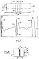
- a plot can be produced of the reflected pulses over time which can be manually analyzed to determine the thickness of the individual layers and the total thickness of the fuel tank wall 11.
- a computer software program analyzes the recorded data and automatically interprets the data into the corresponding thickness of the individual layers.
- a first peak 50 represents the outer surface 52 of the fuel tank 10.
- a second peak 54 represents the interface 56 between the re-grind layer 22 and the outer adhesive layer 24 (as discussed previously, the interface between the outer layer 14 of polyethylene and the re-grind layer 22 is not determinable by ultrasonic measurement).
- a third peak 58 represents the interface 60 between the outer adhesive layer 24 and the vapor barrier layer 16.
- a fourth peak 62 represents the interface 64 between the vapor barrier layer 16 and the inner adhesive layer 26.
- a fifth peak 66 represents the interface 68 between the inner adhesive layer 26 and the inner layer 12 of polyethylene.
- a sixth peak 70 represents the inner surface 72 of the fuel tank wall 11.
- the time between the various peaks represents the transmission time of the ultrasonic signal through the corresponding layer of material.
- the transmission time is the time for: (1) the generated ultrasonic pulse to travel through the layer; and (2) the time for the reflected pulse to travel back through that layer of material.
- the transmission time is equal to twice the time needed for an ultrasonic pulse of the given frequency to travel through the corresponding layer of material. Therefore, the thickness of an individual layer in the multilayer plastic fuel tank 10 can be calculated by multiplying one-half of the transmission time and the average speed of sound in that material. This computation can be easily done either manually or automatically by a microprocessor such as that in the personal computer 40. In a similar manner the total thickness of the entire wall 11 can be calculated.
- the speed of sound in each material is empirically determined by utilizing the apparatus 30 itself and calibrating it by using a separate sample of known thickness of each material for each layer of the wall.
- standard published values of the speed of sound in each material may be utilized and entered into the computer program for calculating the thickness of each layer of material.
- the beginning or exterior surface 52 in contact with the transducer 30 is always characterized by a three peak wave form 80, as shown in Fig. 4, with the third peak 50 representing the exterior surface 52 and the last or innermost surface of the wall is always characterized by a two peak wave form 82 with the first peak 70 representing the innermost surface 72 which is the interface between HDPE material 12 and the atmospheric air within the empty fuel tank.
- the peak of the highest amplitude 58 represents the interface 60 between the outer adhesive layer 24 and the vapor barrier layer 16.
- the next peaks of significant magnitude 54 and 62 correspond to the interfaces 56 and 64, respectively.
- the peak 62 has a negative magnitude due to the change in material at the interface 64 from the material of layer 16 with a higher speed of sound to the material of layer 26 with a lower speed of sound.
- the interface 68 which represents the interface between the inner adhesive layer 26 and the inner HDPE layer 12, is located by selecting the next peak of significant magnitude 66 between the peaks 62 and 70.
- This distinctive wave form enables automated computer analysis utilizing appropriate software to determine each peak 50, 54, 58, 66 and 70 and the valley or peak of negative magnitude 62 of interest and calculations determining the actual thickness of each layer of material 22, 24, 16, 26 and 12 of the multilayer wall 11.
- This recognition of the wave form and calculation of the thickness of each layer may be done by using a program developed by Lab View software and a suitable personal computer.
- This Lab View software is commercially available from National Instruments Company of 6504 Bridge Point Parkway, Austin, Texas 78730-5039.
- the apparatus 30 uses a simple method utilizing an ultrasonic signal to determine the thickness of the individual layers of the multilayer structure such as a multilayer plastic fuel tank 10.
- the signal utilized is at a constant and relatively high frequency providing data with a high resolution and accuracy.
- the method and apparatus 30 utilize commercially available components and can be readily adapted for use with a personal computer 40 to automatically analyze the data and compute the results. Further, this method is non-destructive and considerably less time consuming and labor intensive than previous methods and enables an increased quality control of the manufacture of the fuel tanks 10.
Landscapes
- Physics & Mathematics (AREA)
- General Physics & Mathematics (AREA)
- Length Measuring Devices Characterised By Use Of Acoustic Means (AREA)
- Investigating Or Analyzing Materials By The Use Of Ultrasonic Waves (AREA)
Claims (29)
- Verfahren zum Messen der Dicke von einzelnen Schichten (14, 24, 16, 26, 12) von unterschiedlichen Materialien in einer Mehrschichtstruktur (11) durch Senden von Ultraschallimpulsen, Empfangen von reflektierten Impulsen und Analysieren der reflektierten Impulse mit den folgenden Schritten:(a) Senden eines Ultraschallimpulses mit nur einer konstanten Frequenz in einem Bereich von 10 MHz bis 30 MHz in die Mehrschichtstruktur (11);(b) Empfangen von reflektierten Impulsen von sämtlichen Grenzflächen (52, 56, 60, 64, 68, 72) zwischen allen Materialschichten (14, 24, 16, 26, 12) unterschiedlicher Dichte und Dicke innerhalb der Mehrschichtstruktur (11) und von der Außenfläche und Innenfläche der Mehrschichtstruktur und Verwenden der Welle der Amplitude dieser reflektierten Impulse zur Korrelation der einzelnen Berge oder Täler (50, 54, 58, 62, 66, 70) der Welle mit entsprechenden Grenzflächen (52, 56, 60, 64, 68, 72) der benachbarten Schichten und mit der Außenfläche und Innenfläche der Mehrschichtstruktur (11) in Abhängigkeit von der Zeit;(c) Bestimmen der Durchtrittszeit des Ultraschallimpulses für jede Schicht (14, 24, 16, 26, 12) innerhalb der Mehrschichtstruktur (11), wobei die Durchtrittszeit des Ultraschallimpulses für eine bestimmte Schicht beginnt, wenn ein reflektierter Impuls von einer ersten Fläche dieser Schicht empfangen wird, und endet, wenn ein reflektierter Impuls von einer ersten Fläche der nächsten Schicht empfangen wird; und(d) Bestimmen der Dicke einer jeden Schicht (14, 24, 16, 26, 12) in Abhängigkeit von der Durchtrittszeit und der Schallgeschwindigkeit im Material einer jeden Schicht (14, 24, 16, 26, 12).
- Verfahren nach Anspruch 1, bei dem die Dicke einer Schicht (14, 24, 16, 26, 12) auf der Basis von einer Hälfte der Durchtrittszeit multipliziert mit der Durchschnittsschallgeschwindigkeit im Material der Schicht bestimmt wird.
- Verfahren nach Anspruch 1, bei dem die Schichten (14, 24, 16, 26, 12), die in der Mehrschichtstruktur gemessen werden sollen, aus einem Kunststoffmaterial geformt sind und eine andere Dichte als ihre benachbarten Schichten besitzen.
- Verfahren nach Anspruch 1, bei dem die konstante Frequenz des Ultraschallimpulses zwischen etwa 10 und 20 MHz liegt.
- Verfahren nach Anspruch 1, bei dem die reflektierten Impulse mit einem Wert von 50 MHz bis 150 MHz gesampelt werden.
- Verfahren nach Anspruch 1, bei dem die Mehrschichtstruktur ein Kunststoffkraftstofftank ist, der mindestens eine Außenschicht (14), eine Innenschicht (12) und eine Dampfsperrschicht (16), die zwischen der Außenschicht (14) und der Innenschicht (12) angeordnet ist, aufweist.
- Verfahren nach Anspruch 6, das des weiteren ein Paar von Klebschichten (24, 26) mit einer äußeren Klebschicht (24), die zwischen der Dampfsperrschicht (16) und der Außenschicht (14) angeordnet ist, und einer inneren Klebschicht (26), die zwischen der Dampfsperrschicht (16) und der Innenschicht (12) angeordnet ist, umfasst.
- Verfahren nach Anspruch 6, das des weiteren den Schritt der Aufzeichnung der reflektierten Impulse über der Zeit umfasst, wobei reflektierte Impulse mit der entsprechenden Grenzfläche (52, 56, 60, 64, 68, 72) zwischen benachbarten Materialien auf Basis der empfangen Zeit und von Unterscheidungsmerkmalen, die zwischen Kraftstofftanks entsprechender Konstruktion konstant bleiben, korreliert werden können.
- Verfahren nach Anspruch 8, bei dem in der Aufzeichnung der reflektierten Impulse der Beginn der Außenschicht (14) durch drei eng benachbarte Peaks (80) relativ großer Größe gekennzeichnet ist.
- Verfahren nach Anspruch 8, bei dem in der Aufzeichnung der reflektierten Impulse das Ende der Innenschicht (12) durch ein Paar von eng benachbarten Peaks (82) relativ großer Größe gekennzeichnet ist.
- Verfahren nach Anspruch 8, bei dem in der Aufzeichnung der reflektierten Impulse der Beginn der Dampfsperrschicht (16) durch einen einzigen Peak (58) relativ großer Größe gekennzeichnet ist, der zwischen den reflektierten Impulsen angeordnet ist, die der Innenschicht (14) und der Außenschicht (12) entsprechen.
- Verfahren nach Anspruch 7, das ferner den Schritt der Aufzeichnung der reflektierten Impulse über der Zeit umfasst, wodurch reflektierte Impulse mit der entsprechenden Grenzfläche (52, 56, 60, 64, 68, 72) zwischen benachbarten Materialien auf Basis der empfangenen Merkmale und von Unterscheidungsmerkmalen, die zwischen Kraftstofftanks einer entsprechenden Konstruktion konstant bleiben, korreliert werden können.
- Verfahren nach Anspruch 12, bei dem die Grenzfläche (60) zwischen der äußeren Klebschicht (24) und der Dampfsperrschicht (16) durch einen einzigen Peak (58) gekennzeichnet ist, der die größte Größe besitzt und zwischen den Peaks (82) der Außenschicht (12) und der Innenschicht (14) angeordnet ist.
- Verfahren nach Anspruch 13, bei dem die Grenzfläche (56) zwischen der äußeren Klebschicht (24) und der Außenschicht (14) und die Grenzfläche (64) zwischen der Dampfsperrschicht (16) und der inneren Klebschicht (26) lokalisiert werden, indem der nächste Peak über einer Schwellengröße benachbart zu jeder Seite des Peaks (58), der die Grenzfläche (60) zwischen der äußeren Klebschicht (24) und der Dampfsperrschicht (16) kennzeichnet, ausgewählt wird, wobei der der Grenzfläche zwischen der Dampfsperrschicht (16) und der inneren Klebschicht (26) entsprechende Peak ein negativer Peak oder ein Tal infolge der Änderung der Schallgeschwindigkeit zwischen den Materialien dieser Schichten ist.
- Verfahren nach Anspruch 14, bei dem die Grenzfläche (68) zwischen der inneren Klebschicht (26) und der Innenschicht (12) lokalisiert wird, indem der nächste Peak über einer Schwellengröße benachbart zu dem Peak, der der Grenzfläche (64) zwischen der inneren Klebschicht (26) und der Dampfsperrschicht (16) entspricht, ausgewählt wird.
- Verfahren nach Anspruch 6, bei dem die Dampfsperrschicht (16) nicht mehr als etwa 5 % der Gesamtdicke des Kunststoffkraftstofftanks ausmacht.
- Vorrichtung zum Bestimmen der Dicke einer jeden einzelnen Schicht (14, 24, 16, 26, 12) von unterschiedlichen Materialien in einer Mehrschichtstruktur (11) mit
einem Impulserzeuger (32),
einem Impulsempfänger (34) und
einem Ultraschallgeber (36), der mit dem Impulserzeuger (32) und dem Impulsempfänger (34) gekoppelt ist, wobei der Impulserzeuger (32) ein elektrisches Signal erzeugt, das den Ultraschallgeber (36) in Vibrationen versetzt, um einen Ultraschallimpuls mit nur einer im wesentlichen konstanten Frequenz in einem Bereich von 10 MHz bis 30 MHz in die Mehrschichtstruktur (11) abzugeben, woraufhin reflektierte Impulse von jeder Grenzfläche (56, 60, 64, 68) zwischen benachbarten Schichten (24, 16, 26) und von der Innenfläche (72) und der Außenfläche (52) der Innenschicht (12) und der Außenschicht (14) der Mehrschichtstruktur (11) zum Ultraschallgeber (36) zurückgeführt, dem Impulsempfänger (34) zugeführt und in Abhängigkeit von der Zeit aufgezeichnet werden, um die Bestimmung der Dicke einer jeden einzelnen Schicht (14, 24, 16, 26, 12) der Mehrschichtstruktur (11) in Abhängigkeit von der Zeit zwischen ausgewählten Bergen und Tälern (50, 54, 58, 62, 66, 70) der Welle der reflektierten Impulse und der Schallgeschwindigkeit für das Material einer jeden unterschiedlichen Schicht (14, 24, 16, 26, 12) zu ermöglichen. - Vorrichtung nach Anspruch 17, die des weiteren einen Analog-Digital-Wandler (38), der mit dem Impulsempfänger (34) gekoppelt ist, um die vom Impulsempfänger empfangenen Impulse in eine digitale Form zu überführen, und einen Mikroprozessor (40) umfasst, der mit dem Wandler gekoppelt und so ausgebildet ist, dass er die relative Empfangszeit von reflektierten Impulsen ermittelt und auf diese Weise die Dicke der einzelnen Schichten (14, 24, 16, 26, 12) in Abhängigkeit von der Schallgeschwindigkeit im Material der einzelnen Schichten bestimmt.
- Vorrichtung nach Anspruch 18, bei der der Mikroprozessor ein Computer (40) mit einer Software ist, mit der die Dicke von einzelnen Schichten (14, 24, 16, 26, 12) auf der Basis des digitalen Ausgangssignals des Wandlers (38) bestimmt werden kann.
- Vorrichtung nach Anspruch 18, bei der die Impulsquelle, der Impulsempfänger und der Wandler (38) Hardware-Komponenten des Computers (40) sind.
- Vorrichtung nach Anspruch 18, bei der der Wandler (38) eine Samplingrate zwischen 50 MHz und 150 MHz besitzt.
- Vorrichtung nach Anspruch 17, bei der der Ultraschallgeber (36) ein solcher vom Kontakttyp ist und ein Luftverdrängungsmedium zwischen der Mehrschichtstruktur (11) und dem Ultraschallgeber (36) angeordnet ist, um jegliche Luft hierzwischen auszuschließen.
- Vorrichtung nach Anspruch 17, die des weiteren einen Analog-Digital-Wandler (38), der mit dem Impulsempfänger (34) gekoppelt ist, um die vom Impulsempfänger (34) empfangenen Impulse in digitale Form zu überführen, und einen Computer (45) umfasst, der mit dem Wandler (38) verbunden ist und Software aufweist, die so ausgebildet ist, dass hiermit die Dicke einer jeden einzelnen Schicht (14, 24, 16, 26, 12) der Mehrschichtstruktur (11) mit mindestens einer Außenschicht (14), einer äußeren Klebschicht (24), einer Dampfsperrschicht (16), einer inneren Klebschicht (26) und einer Innenschicht (12) bestimmt werden kann.
- Vorrichtung nach Anspruch 23, dadurch gekennzeichnet, dass der Computer (40) und die Software in der Lage sind, den Peak (50) der Welle der reflektierten Impulse, der dem Beginn der Außenschicht (14) entspricht und durch drei eng benachbarte Peaks (80) einer relativ großen Größe der Welle gekennzeichnet ist, zu bestimmen.
- Vorrichtung nach Anspruch 23, dadurch gekennzeichnet, dass der Computer (40) und die Software in der Lage sind, den Peak (70) der Welle zu bestimmen, der dem Ende der Innenschicht (12) entspricht und durch ein Paar von eng benachbarten Peaks (82) einer relativ großen Größe der Welle gekennzeichnet ist.
- Vorrichtung nach Anspruch 23, dadurch gekennzeichnet, dass der Computer (40) und die Software in der Lage sind, den Peak (58) der Welle zu bestimmen, der dem Beginn der Dampfsperrschicht (16) entspricht und durch einen einzigen Peak (58) einer relativ großen Größe zwischen den reflektierten Impulsen, die der Innenschicht (14) und der Außenschicht (12) entsprechen, gekennzeichnet ist.
- Vorrichtung nach Anspruch 23, dadurch gekennzeichnet, dass der Computer (40) und die Software in der Lage sind, den Impuls (58) entsprechend der Grenzfläche (60) zwischen der äußeren Klebschicht (24) und der Dampfsperrschicht (16) zu bestimmen, der durch einen einzigen Peak (58) mit der größten Größe gekennzeichnet ist, welcher zwischen den Peaks (50, 70) der Außenschicht (14) und der Innenschicht (12) angeordnet ist.
- Vorrichtung nach Anspruch 27, dadurch gekennzeichnet, dass der Computer (40) und die Software in der Lage sind, die Grenzfläche (56) zwischen der äußeren Klebschicht (24) und der Außenschicht (14) und die Grenzfläche (64) zwischen der Dampfsperrschicht (16) und der inneren Klebschicht (26) zu bestimmen, indem sie den nächsten Peak (54, 62) auswählen, der größer ist als eine Schwellengröße benachbart zu jeder Seite des Peaks (58), der die Grenzfläche (60) zwischen der äußeren Klebschicht (24) und der Dampfsperrschicht (16) kennzeichnet, wobei der Peak (62) entsprechend der Grenzfläche (64) zwischen der Dampfsperrschicht (16) und der inneren Klebschicht (26) ein Tal (62) oder ein negativer Peak infolge der Änderung der Schallgeschwindigkeit zwischen den Materialien dieser Schichten (16, 26) ist.
- Vorrichtung nach Anspruch 28, dadurch gekennzeichnet, dass der Computer (40) und die Software in der Lage sind, die Grenzfläche (68) zwischen der inneren Klebschicht (26) und der Innenschicht (12) zu bestimmen, indem sie den nächsten Peak (66) über einer Schwellengröße benachbart zu dem Peak (62) entsprechend der Grenzfläche (64) zwischen der inneren Klebschicht (26) und der Dampfsperrschicht (16) auswählen.
Applications Claiming Priority (2)
| Application Number | Priority Date | Filing Date | Title |
|---|---|---|---|
| US08/910,124 US5866819A (en) | 1997-08-12 | 1997-08-12 | Ultrasonic thickness measurement of multilayer structures |
| US910124 | 1997-08-12 |
Publications (3)
| Publication Number | Publication Date |
|---|---|
| EP0897099A2 EP0897099A2 (de) | 1999-02-17 |
| EP0897099A3 EP0897099A3 (de) | 2000-10-04 |
| EP0897099B1 true EP0897099B1 (de) | 2005-10-26 |
Family
ID=25428339
Family Applications (1)
| Application Number | Title | Priority Date | Filing Date |
|---|---|---|---|
| EP98115026A Expired - Lifetime EP0897099B1 (de) | 1997-08-12 | 1998-08-10 | Ultraschalldickenmessgerät für Mehrschichtstrukturen |
Country Status (4)
| Country | Link |
|---|---|
| US (1) | US5866819A (de) |
| EP (1) | EP0897099B1 (de) |
| DE (1) | DE69832012T2 (de) |
| NO (1) | NO983549L (de) |
Families Citing this family (15)
| Publication number | Priority date | Publication date | Assignee | Title |
|---|---|---|---|---|
| US5723791A (en) * | 1993-09-28 | 1998-03-03 | Defelsko Corporation | High resolution ultrasonic coating thickness gauge |
| CA2175609C (en) * | 1995-05-12 | 2004-06-22 | Hata, Nobuhiko | Fuel tank |
| EP1108593A3 (de) * | 1999-12-18 | 2003-10-15 | Delphi Technologies, Inc. | Kraftstofftank mit einer Kraftstoffpermeationssperre |
| US6589620B1 (en) * | 1999-12-18 | 2003-07-08 | Delphi Technologies, Inc. | Fuel permeation resistant fuel tank |
| US6586064B1 (en) * | 1999-12-18 | 2003-07-01 | Delphi Technologies, Inc. | Fuel permeation barrier fuel tank |
| US6494097B1 (en) * | 2000-09-05 | 2002-12-17 | Elias Edmond Shihadeh | Method and apparatus for measuring thickness of a layer in a multi-layered object |
| US6883376B2 (en) * | 2001-01-23 | 2005-04-26 | Wright State University | Method for determining the wall thickness and the speed of sound in a tube from reflected and transmitted ultrasound pulses |
| US20040100282A1 (en) * | 2002-09-11 | 2004-05-27 | Henrik Christensen | Method and apparatus for determination of layer thickness in a multi-layer structure |
| NO330292B1 (no) * | 2007-09-12 | 2011-03-21 | Det Norske Veritas As | Akustiske tykkelsesmalinger ved bruk av gass som et koblingsmedium |
| DE102008044738B4 (de) | 2008-08-28 | 2011-04-21 | Eads Deutschland Gmbh | Sensoranordnung und Detektionsverfahren zur Messung einer Eisschicht |
| JP4977750B2 (ja) * | 2009-12-24 | 2012-07-18 | 本田技研工業株式会社 | 樹脂製燃料タンク |
| JP5636259B2 (ja) * | 2009-12-24 | 2014-12-03 | 本田技研工業株式会社 | 汎用エンジンの樹脂製燃料タンク |
| AT513852B1 (de) | 2013-04-04 | 2014-08-15 | Constantia Teich Gmbh | Verfahren zur Ermittlung der Schichtdicke einer Verbindungsschicht zwischen zwei Verpackungsschichten |
| CN106979761B (zh) * | 2016-01-18 | 2020-07-07 | 中国电力科学研究院 | 一种锂离子电池内部各层级厚度及表面形貌的检测方法 |
| DE102016216446A1 (de) | 2016-08-31 | 2018-03-01 | Kautex Textron Gmbh & Co. Kg | Kunststoffformteil aus einem extrudierten Mehrschichtverbund sowie Kraftstoffbehälter aus einem extrudierten Mehrschichtverbund |
Family Cites Families (12)
| Publication number | Priority date | Publication date | Assignee | Title |
|---|---|---|---|---|
| US3934458A (en) * | 1974-02-04 | 1976-01-27 | Technicon Instruments Corporation | Method and apparatus for pulse echo imaging |
| US4167880A (en) * | 1978-05-22 | 1979-09-18 | The Boeing Company | Water coupled ultrasonic through transmission apparatus |
| US4738139A (en) * | 1987-01-09 | 1988-04-19 | Blessing Gerald V | Ultrasonic real-time monitoring device for part surface topography and tool condition in situ |
| US5001932A (en) * | 1989-06-22 | 1991-03-26 | General Dynamics Corporation | Ultrasonic squirter |
| US5038615A (en) * | 1990-05-11 | 1991-08-13 | General Motors Corporation | Ultrasonic multilayer paint thickness measurement |
| US5167157A (en) * | 1991-03-26 | 1992-12-01 | Ball Corporation | Nondestructive inspection system for laminated products |
| JP2971174B2 (ja) * | 1991-05-17 | 1999-11-02 | 日産自動車株式会社 | 多層樹脂成形品の非破壊検査方法 |
| US5271274A (en) * | 1991-08-14 | 1993-12-21 | The Board Of Trustees Of The Leland Stanford Junior University | Thin film process monitoring techniques using acoustic waves |
| MY111633A (en) * | 1991-12-17 | 2000-10-31 | Schlumberger Technology Bv | Method and apparatus for hydraulic isolation determination |
| JPH05187856A (ja) * | 1992-01-09 | 1993-07-27 | Tonen Chem Corp | 樹脂積層体の層厚測定方法 |
| JP3085784B2 (ja) * | 1992-06-08 | 2000-09-11 | 昭和電工株式会社 | 多層積層構造材 |
| US5608165A (en) * | 1996-05-06 | 1997-03-04 | Ford Motor Company | Ultrasonic thickness gauge for multilayer plastic fuel tanks |
-
1997
- 1997-08-12 US US08/910,124 patent/US5866819A/en not_active Expired - Lifetime
-
1998
- 1998-08-03 NO NO983549A patent/NO983549L/no unknown
- 1998-08-10 DE DE69832012T patent/DE69832012T2/de not_active Expired - Fee Related
- 1998-08-10 EP EP98115026A patent/EP0897099B1/de not_active Expired - Lifetime
Also Published As
| Publication number | Publication date |
|---|---|
| NO983549L (no) | 1999-02-15 |
| NO983549D0 (no) | 1998-08-03 |
| EP0897099A2 (de) | 1999-02-17 |
| DE69832012D1 (de) | 2005-12-01 |
| US5866819A (en) | 1999-02-02 |
| DE69832012T2 (de) | 2006-07-20 |
| EP0897099A3 (de) | 2000-10-04 |
Similar Documents
| Publication | Publication Date | Title |
|---|---|---|
| EP0897099B1 (de) | Ultraschalldickenmessgerät für Mehrschichtstrukturen | |
| US5303590A (en) | Method of and an apparatus for frequency selective ultrasonic inspection of multi-layered structures | |
| EP2472254B1 (de) | Verfahren zur zerstörungsfreien ultraschallprüfung, inbesondere für verbundwerkstoffstrukturen für aeronautische anwendungen | |
| EP3543687B1 (de) | Nachweis von schwachen bindungen in verbundkomponenten | |
| US6959602B2 (en) | Ultrasonic detection of porous medium characteristics | |
| EP1474680B1 (de) | System und verfahren zur detektion von fehlern in fertigungsobjekten | |
| US5608165A (en) | Ultrasonic thickness gauge for multilayer plastic fuel tanks | |
| CA2258913C (en) | Ultrasonic technique for inspection of weld and heat-affected zone for localized high temperature hydrogen attack | |
| Kusano et al. | Simultaneous sound velocity and thickness measurement by the ultrasonic pitch-catch method for corrosion-layer-forming polymeric materials | |
| Wang et al. | Determination of embedded layer properties using adaptive time-frequency domain analysis | |
| EP0226638A1 (de) | Messverfahren des neigungswinkels eines risses auf der oberfläche in einem erzeugnis mittels ultraschall | |
| CN111189914B (zh) | 一种用于复合材料超声检测的渐变厚度系数的确定方法 | |
| US4760304A (en) | Dark field coaxial ultrasonic transducer | |
| CN119470203A (zh) | 一种孔隙率均匀性的融合标定方法及系统 | |
| Schafer | Ultrasound for defect detection and grading in wood and lumber | |
| JPH05187856A (ja) | 樹脂積層体の層厚測定方法 | |
| US4787126A (en) | Method of fabricating dark field coaxial ultrasonic transducer | |
| CN117849182A (zh) | 一种电阻点焊接头实时成像与质量评估方法 | |
| US4380929A (en) | Method and apparatus for ultrasonic detection of near-surface discontinuities | |
| JPH04340464A (ja) | 多層樹脂成形品の非破壊検査方法 | |
| JPH06300550A (ja) | 層状材料の超音波による層厚さ測定法 | |
| JPH09236585A (ja) | 表面劣化、硬化、疲労等の度合の診断用測定センサ及び診断装置並びに診断方法 | |
| JP2000310522A (ja) | 二層構造金属体の厚さ測定方法 | |
| JP7273375B2 (ja) | 接着接合部の劣化計測装置及び劣化計測方法 | |
| Sharma | Low-velocity impact damage detection using coda waves on CFRP laminates |
Legal Events
| Date | Code | Title | Description |
|---|---|---|---|
| PUAI | Public reference made under article 153(3) epc to a published international application that has entered the european phase |
Free format text: ORIGINAL CODE: 0009012 |
|
| AK | Designated contracting states |
Kind code of ref document: A2 Designated state(s): BE DE FR GB |
|
| AX | Request for extension of the european patent |
Free format text: AL;LT;LV;MK;RO;SI |
|
| PUAL | Search report despatched |
Free format text: ORIGINAL CODE: 0009013 |
|
| AK | Designated contracting states |
Kind code of ref document: A3 Designated state(s): AT BE CH CY DE DK ES FI FR GB GR IE IT LI LU MC NL PT SE |
|
| AX | Request for extension of the european patent |
Free format text: AL;LT;LV;MK;RO;SI |
|
| RIC1 | Information provided on ipc code assigned before grant |
Free format text: 7G 01B 17/02 A, 7G 01N 29/10 B |
|
| 17P | Request for examination filed |
Effective date: 20010309 |
|
| AKX | Designation fees paid |
Free format text: BE DE FR GB |
|
| 17Q | First examination report despatched |
Effective date: 20021118 |
|
| GRAP | Despatch of communication of intention to grant a patent |
Free format text: ORIGINAL CODE: EPIDOSNIGR1 |
|
| GRAS | Grant fee paid |
Free format text: ORIGINAL CODE: EPIDOSNIGR3 |
|
| GRAA | (expected) grant |
Free format text: ORIGINAL CODE: 0009210 |
|
| AK | Designated contracting states |
Kind code of ref document: B1 Designated state(s): BE DE FR GB |
|
| REG | Reference to a national code |
Ref country code: GB Ref legal event code: FG4D |
|
| REF | Corresponds to: |
Ref document number: 69832012 Country of ref document: DE Date of ref document: 20051201 Kind code of ref document: P |
|
| ET | Fr: translation filed | ||
| PGFP | Annual fee paid to national office [announced via postgrant information from national office to epo] |
Ref country code: GB Payment date: 20060825 Year of fee payment: 9 |
|
| PGFP | Annual fee paid to national office [announced via postgrant information from national office to epo] |
Ref country code: FR Payment date: 20060831 Year of fee payment: 9 |
|
| PLBE | No opposition filed within time limit |
Free format text: ORIGINAL CODE: 0009261 |
|
| STAA | Information on the status of an ep patent application or granted ep patent |
Free format text: STATUS: NO OPPOSITION FILED WITHIN TIME LIMIT |
|
| PGFP | Annual fee paid to national office [announced via postgrant information from national office to epo] |
Ref country code: BE Payment date: 20060918 Year of fee payment: 9 |
|
| PGFP | Annual fee paid to national office [announced via postgrant information from national office to epo] |
Ref country code: DE Payment date: 20061002 Year of fee payment: 9 |
|
| 26N | No opposition filed |
Effective date: 20060727 |
|
| BERE | Be: lapsed |
Owner name: *WALBRO CORP. Effective date: 20070831 |
|
| GBPC | Gb: european patent ceased through non-payment of renewal fee |
Effective date: 20070810 |
|
| REG | Reference to a national code |
Ref country code: FR Ref legal event code: ST Effective date: 20080430 |
|
| PG25 | Lapsed in a contracting state [announced via postgrant information from national office to epo] |
Ref country code: DE Free format text: LAPSE BECAUSE OF NON-PAYMENT OF DUE FEES Effective date: 20080301 |
|
| PG25 | Lapsed in a contracting state [announced via postgrant information from national office to epo] |
Ref country code: BE Free format text: LAPSE BECAUSE OF NON-PAYMENT OF DUE FEES Effective date: 20070831 |
|
| PG25 | Lapsed in a contracting state [announced via postgrant information from national office to epo] |
Ref country code: FR Free format text: LAPSE BECAUSE OF NON-PAYMENT OF DUE FEES Effective date: 20070831 |
|
| PG25 | Lapsed in a contracting state [announced via postgrant information from national office to epo] |
Ref country code: GB Free format text: LAPSE BECAUSE OF NON-PAYMENT OF DUE FEES Effective date: 20070810 |