EP0897099B1 - Ultrasonic thickness measurement of multilayer structures - Google Patents
Ultrasonic thickness measurement of multilayer structures Download PDFInfo
- Publication number
- EP0897099B1 EP0897099B1 EP98115026A EP98115026A EP0897099B1 EP 0897099 B1 EP0897099 B1 EP 0897099B1 EP 98115026 A EP98115026 A EP 98115026A EP 98115026 A EP98115026 A EP 98115026A EP 0897099 B1 EP0897099 B1 EP 0897099B1
- Authority
- EP
- European Patent Office
- Prior art keywords
- layer
- peak
- interface
- vapor barrier
- pulse
- Prior art date
- Legal status (The legal status is an assumption and is not a legal conclusion. Google has not performed a legal analysis and makes no representation as to the accuracy of the status listed.)
- Expired - Lifetime
Links
Images

Classifications
-
- G—PHYSICS
- G01—MEASURING; TESTING
- G01B—MEASURING LENGTH, THICKNESS OR SIMILAR LINEAR DIMENSIONS; MEASURING ANGLES; MEASURING AREAS; MEASURING IRREGULARITIES OF SURFACES OR CONTOURS
- G01B17/00—Measuring arrangements characterised by the use of infrasonic, sonic or ultrasonic vibrations
- G01B17/02—Measuring arrangements characterised by the use of infrasonic, sonic or ultrasonic vibrations for measuring thickness
- G01B17/025—Measuring arrangements characterised by the use of infrasonic, sonic or ultrasonic vibrations for measuring thickness for measuring thickness of coating
-
- G—PHYSICS
- G01—MEASURING; TESTING
- G01N—INVESTIGATING OR ANALYSING MATERIALS BY DETERMINING THEIR CHEMICAL OR PHYSICAL PROPERTIES
- G01N2291/00—Indexing codes associated with group G01N29/00
- G01N2291/04—Wave modes and trajectories
- G01N2291/044—Internal reflections (echoes), e.g. on walls or defects
Definitions
- This invention relates generally to ultrasonic measuring and more particularly to an ultrasonic method and apparatus for measuring the thickness of individual layers of different materials of a multilayer structure.
- a typical multilayer plastic fuel tank construction comprises an outer layer of high density polyethylene, an inner layer of high density polyethylene, and a vapor barrier layer disposed between them.
- the vapor barrier layer is typically a polymer such as ethylene vinyl alcohol which requires an adhesive layer adjacent both the outer and inner layers to join the high density polyethylene with the ethylene vinyl alcohol.
- a multilayer plastic fuel tank is more difficult to manufacture than a single layer plastic fuel tank. In mass production, to insure the quality of multilayer fuel tanks and the vapor barrier, it is important to determine the thickness of the individual layers of the multilayer structure and in particular the adhesive and barrier layers both from one tank to the next and at various locations within an individual tank. The most critical and difficult areas to measure tend to be at the corners, edges and other areas of the tank where the contour of the multilayer wall changes rapidly.
- testing and sampling of manufactured plastic fuel tanks required cutting a cross section from various portions of the fuel tanks and preparing each cross section to be visually inspected under a microscope to measure the thickness of the various layers. This is undesirable because of the time required to prepare and inspect the sample cross sections of the fuel tank and also because of the destruction of the fuel tank as well as the scrap and waste created when conducting such a test.
- Patent Abstracts of Japan, vol. 017, no. 609 (P-1640), and JP 05 187856 A disclose a method for measuring thickness of a resin laminated body, more particularly to quickly and accurately measure the thickness of each layer of a product composed of a laminated body constituted of thin resin layers having similar compositions without destroying the product.
- ultrasonic waves having a first frequency of 4-6 MHz and second frequency of 10-20 MHz are transmitted toward the laminated body composed of the resin layers. Then, after receiving the reflected waves, the time from the transmission to the reception of the waves for each resin layer is converted into the thickness of each resin layer.
- US-A-5 038 615 discloses a method of measuring layer thicknesses of multiple thin layers separated by layer interfaces comprising the steps of transmitting ultrasonic pulses through the layers, receiving echo pulses reflected from the layer interfaces, deriving from the echo pulses a signal wave form revealing characteristic echo pulse shapes, determining zones in the signal wave form corresponding to predicting positions of the layer interfaces, locating candidate co-pulse shapes in one of the zones, grading the candidate echo pulse shapes, selecting one of the candidate echo pulse shapes having a best score and storing a position thereof in the signal wave form corresponding to the location of one of the layer interfaces, repeating the locating, grading and selecting steps for at least another zone to select another candidate echo pulse shape and store a position thereof in the signal wave form corresponding to the location of another of the layer interfaces, and determining layer thickness from the stored positions of the selected candidate co-pulse shapes in adjacent zones.
- a very high transducer frequency is utilized, on the order of 125
- a non-destructive method and apparatus for determining the thickness of individual layers of different materials in a multilayer structure and particularly a multilayer plastic fuel tank utilizes a constant frequency and relatively high frequency ultrasonic pulse transmitted into the multilayer structure and records the times when echos are received to determine the thickness of the individual layers in the multilayer structure.
- An echo pulse is generated at the interface between adjacent layers of materials having a sufficiently different density or index of refraction and thus, the time between transmitted and echo pulses is a function of the amount of time needed for the ultrasonic pulse to pass through a layer of material.
- the duration between transmitted and reflected pulses is called the transmission time which is the time for the ultrasonic frequency transmitted pulse to originally pass through the material and also the time for the reflected pulse to bounce back to the transducer and is thus equal to twice the time needed for the ultrasonic pulse to pass through the layer. Therefore, the thickness of a layer within a multilayer structure can be readily computed as one-half of the transmission time multiplied by the speed of sound through the material comprising that layer.
- Either immersion or preferably contact type transducers may be used with the present invention to transmit the ultrasonic pulse which is generated and conveyed to the transducer by a pulse source.
- the transducer also senses the reflected pulses and relays them to a pulse receiver which may display the pulses as a function of transmission time for manual calculation of the layer thickness.
- an analog-to-digital converter is coupled with the pulse receiver to digitize the data from the reflected pulses received so that they may be analyzed by a microprocessor which performs the thickness calculations automatically.
- the microprocessor is a personal computer and the pulse source, pulse receiver and analog-to-digital converter are hardware components of the personal computer enabling fast, easy, reliable and efficient analyzing of the results.
- the present invention provides a non-destructive method and apparatus for determining the thickness of individual layers in a multilayer structure such as a plastic fuel tank, to ensure the quality of the fuel tanks throughout a production run of tanks. Further, the data gathered during the ultrasonic testing can be either manually analyzed or automatically analyzed by a personal computer thereby greatly reducing the time needed to conduct the test.
- Objects, features and advantages of this invention include providing a method and apparatus for determining the thickness of individual layers of a multilayer structure that does not require destruction of the fuel tanks tested, can determine the thickness of individual layers of a sharply curved multilayer structure, is less time consuming than destructive testing methods, can be substantially automated and used with a personal computer, utilizes relatively high ultrasonic frequencies and a high sampling rate for increased resolution and reliability of the data obtained, can utilize commercially available hardware and software as well as commercially available transducers, utilizes a single ultrasonic frequency, can simultaneously determine the thickness of multiple layers, is not dependent on the relative thickness of adjacent layers, provides reliable data, is of relatively simple design and economical manufacture, is simple to use and provides fast and accurate data to help increase the quality of production of multilayer plastic fuel tanks.
- FIG. 1 shows a multilayer molded plastic fuel tank 10 as is commonly used, for example, in the automotive industry.
- the walls 11 of the fuel tank 10 preferably have inner 12 and outer 14 layers formed primarily of polyethylene and an intermediate vapor barrier layer 16 formed of a copolymer such as ethylene vinyl alcohol to reduce he permeation of fuel vapor through the fuel tank 10.
- the tank walls 11 may be formed by coextruding the various layers of different materials.
- the plastic fuel tanks 10 are particularly desirable because cf their light weight, resistance to corrosion and ease of manufacturing.
- the fuel tank 10 has multiple layers including: an outer layer 14 of high density polyethylene (HDPE) which may also have some carbon black or poly black mixed therein to provide coloration; a re-grind layer 22 of HDPE which is composed of re-ground scrap materials from the manufacturing of the fuel tanks 10 and/or salvaged and re-ground HDPE; an outer adhesive layer 24; the vapor barrier layer 16; an inner adhesive layer 26; and an inner layer 12 of virgin high density polyethylene.
- the vapor barrier layer 16 is preferably ethylene vinyl alcohol (EVOH) and the adhesive layers may be of a wide variety of materials with one current example sold under the trade name ADMER by Evalca, Inc..
- the inner and outer adhesive layers 24, 26 are necessary to attach the adjacent layers of HDPE to the vapor barrier layer 16 and thereby increase the structural integrity of the fuel tank 10 which is paramount for passing various crush resistance specifications in the automotive industry.
- the vapor barrier layer 16 is necessary to reduce the amount of hydrocarbon vapors which would diffuse or escape through the fuel tank walls 11 which are composed primarily of HDPE.
- the outer layer 14 and re-grind layer 22 are of substantially the same composition such that they cannot be differentiated with ultrasonic measurements.
- a typical multilayer plastic fuel tank wall 11 has a thickness of between about 2.5 mm and 8 mm, with an optimal total wall thickness of about 5 mm.
- Nominal values for the individual layers of the multilayer plastic fuel tank 10 are as follows: the outer layer 14 plus the re-grind layer 22 comprise between about 40 to 50 percent of the total wall thickness; the outer adhesive layer 24 comprises between about 1 to 4 percent of the total wall thickness; the vapor barrier layer 16 comprises between about 2 to 5 percent of the total wall thickness; the inner adhesive layer 26 comprises between about 1 to 4 percent of the total wall thickness; and the inner layer 12 comprises between about 40 and 50 percent of the total wall thickness.
- These ranges of the thickness of the individual layers are illustrative only, and can be readily varied during the coextrusion of the fuel tank walls 11 during the manufacture of the fuel tanks 10.
- the thickness of the individual layers must be controlled to assure optimum performance and quality of the fuel tank 10 in use.
- the thickness of the inner 12 and outer 14 layers of polyethylene is important because these layers provide structural protection of the vapor barrier layer 16 and also the structural integrity of the fuel tank 10 itself.
- the thickness of the adhesive layers 24, 26 is important to insure adequate attachment between the adjacent layers of HDPE and the vapor barrier layer 16.
- the thickness of the vapor barrier layer 16 is important to prohibit the permeation of the hydrocarbon vapors through the fuel tank 10 and into the atmosphere.
- an apparatus 30 which utilizes an ultrasonic method to determine the thickness of the individual layers of the multilayer plastic fuel tank 10.
- the apparatus 30 has a pulse source 32, a pulse receiver 34 and an ultrasonic transducer 36 coupled to the pulse source 32 and to the pulse receiver 34.
- the pulse source 32 produces an electrical signal which intermittently vibrates the transducer 36 at a known constant frequency to send an ultrasonic pulse into the multilayer plastic fuel tank 10 whereupon echos, or reflected pulses are generated at the interfaces of different layers within the fuel tank 10.
- the reflected pulses are returned to the transducer 36 and vibrate it whereupon these vibrations are communicated to the pulse receiver 34 as electrical pulses which are recorded and which enable the determination of the thickness of the individual layers of the fuel tank 10.
- an analog-to-digital converter 38 is coupled with the pulse receiver 34 to convert the pulses received into digital form whereby they may be automatically processed by a microprocessor such as a personal computer 40.
- a microprocessor such as a personal computer 40.
- the pulse source 32, pulse receiver 34 and analog-to-digital converter 38 are all commercially available hardware components for a personal computer 40 which may be readily connected to the computer 40.
- the personal computer 40 may be adapted with software capable of interpreting the recorded data from the ultrasonic transmissions to automatically interpret the received data into the thicknesses of the various layers.
- ISA cards Current hardware components which have been sued include a combination pulse source 32 and pulse receiver 34 sold under the name Matec SR9000 series and an STR8100 series analog-to-digital converter 38 both of which are ISA cards and can be installed as part of the personal computer 40 configuration.
- the ISA cards are commercially available from Matec Instruments, Inc. of 56 Hudson Street, Northborough, MA 01532, USA.
- the transducer 36 is preferably of the contact type which directly contacts the outer surface of the fuel tank 10.
- a liquid medium such as water 37 is necessary with the contact type transducer to remove any air from the interface between the transducer transmission face and the fuel tank surface.
- the transducer 36' may be of the immersion type which transmits the ultrasonic pulse through a liquid coupling medium such as oil 39 and forces it through a lens onto the tank wall 11 without physically bearing on the tank. With an immersion transducer the ultrasonic pulse is usually focused onto the tank wall by varying the distance between them.
- the contact type transducer is preferred because it provides much better resolution when measuring curved surfaces, such as a curve adjacent the corners and edges of the fuel tank, and it eliminates the need to focus the transducer which would be required with an immersion type transducer.
- a suitable contact transducer 36 is commercially available from Technisonic Research, Inc., 777 Commerce Drive, Fairfield, CT 06432, USA.
- Transducers 36 operating at different constant frequencies may be utilized to provide a signal with a resolution optimized for the particular multilayer structure being measured.
- Empirical data has shown that for a typical plastic fuel tank 10 having individual layers of the materials and thicknesses as previously described and a total thickness of about 5 mm, the optimal frequency is about 15 MHz. With this frequency, a strong resolution of the signal is obtained which provides a good definition of each of the individual layers as well as the total wall 11 thickness.
- the higher the frequency the greater the resolution of the signal however, higher frequencies are more quickly attenuated in HDPE than are low frequencies. This greatly limits the use of higher frequencies with an optimal frequency range determined through experimentation to be between about 10 MHz to 20 MHz.
- the pulse receiver 34 preferably has a high sampling rate which is preferably on the order of about 100 MHz. This will obtain a multitude of data points which will provide an accurate plot of the reflected pulses over time.
- the user places the transducer 36 on the desired portion of the fuel tank 10 to be measured whereupon the pulse source 32 generates an electrical signal which vibrates the transducer 36 at the desired frequency.
- the user freezes the signal by triggering a switch 42 (such as a computer mouse) attached to the personal computer 40, and a short ultrasonic pulse is generated in the transducer 36 and transferred into the wall 11 of the plastic fuel tank 10.
- a switch 42 such as a computer mouse
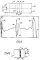
- a plot can be produced of the reflected pulses over time which can be manually analyzed to determine the thickness of the individual layers and the total thickness of the fuel tank wall 11.
- a computer software program analyzes the recorded data and automatically interprets the data into the corresponding thickness of the individual layers.
- a first peak 50 represents the outer surface 52 of the fuel tank 10.
- a second peak 54 represents the interface 56 between the re-grind layer 22 and the outer adhesive layer 24 (as discussed previously, the interface between the outer layer 14 of polyethylene and the re-grind layer 22 is not determinable by ultrasonic measurement).
- a third peak 58 represents the interface 60 between the outer adhesive layer 24 and the vapor barrier layer 16.
- a fourth peak 62 represents the interface 64 between the vapor barrier layer 16 and the inner adhesive layer 26.
- a fifth peak 66 represents the interface 68 between the inner adhesive layer 26 and the inner layer 12 of polyethylene.
- a sixth peak 70 represents the inner surface 72 of the fuel tank wall 11.
- the time between the various peaks represents the transmission time of the ultrasonic signal through the corresponding layer of material.
- the transmission time is the time for: (1) the generated ultrasonic pulse to travel through the layer; and (2) the time for the reflected pulse to travel back through that layer of material.
- the transmission time is equal to twice the time needed for an ultrasonic pulse of the given frequency to travel through the corresponding layer of material. Therefore, the thickness of an individual layer in the multilayer plastic fuel tank 10 can be calculated by multiplying one-half of the transmission time and the average speed of sound in that material. This computation can be easily done either manually or automatically by a microprocessor such as that in the personal computer 40. In a similar manner the total thickness of the entire wall 11 can be calculated.
- the speed of sound in each material is empirically determined by utilizing the apparatus 30 itself and calibrating it by using a separate sample of known thickness of each material for each layer of the wall.
- standard published values of the speed of sound in each material may be utilized and entered into the computer program for calculating the thickness of each layer of material.
- the beginning or exterior surface 52 in contact with the transducer 30 is always characterized by a three peak wave form 80, as shown in Fig. 4, with the third peak 50 representing the exterior surface 52 and the last or innermost surface of the wall is always characterized by a two peak wave form 82 with the first peak 70 representing the innermost surface 72 which is the interface between HDPE material 12 and the atmospheric air within the empty fuel tank.
- the peak of the highest amplitude 58 represents the interface 60 between the outer adhesive layer 24 and the vapor barrier layer 16.
- the next peaks of significant magnitude 54 and 62 correspond to the interfaces 56 and 64, respectively.
- the peak 62 has a negative magnitude due to the change in material at the interface 64 from the material of layer 16 with a higher speed of sound to the material of layer 26 with a lower speed of sound.
- the interface 68 which represents the interface between the inner adhesive layer 26 and the inner HDPE layer 12, is located by selecting the next peak of significant magnitude 66 between the peaks 62 and 70.
- This distinctive wave form enables automated computer analysis utilizing appropriate software to determine each peak 50, 54, 58, 66 and 70 and the valley or peak of negative magnitude 62 of interest and calculations determining the actual thickness of each layer of material 22, 24, 16, 26 and 12 of the multilayer wall 11.
- This recognition of the wave form and calculation of the thickness of each layer may be done by using a program developed by Lab View software and a suitable personal computer.
- This Lab View software is commercially available from National Instruments Company of 6504 Bridge Point Parkway, Austin, Texas 78730-5039.
- the apparatus 30 uses a simple method utilizing an ultrasonic signal to determine the thickness of the individual layers of the multilayer structure such as a multilayer plastic fuel tank 10.
- the signal utilized is at a constant and relatively high frequency providing data with a high resolution and accuracy.
- the method and apparatus 30 utilize commercially available components and can be readily adapted for use with a personal computer 40 to automatically analyze the data and compute the results. Further, this method is non-destructive and considerably less time consuming and labor intensive than previous methods and enables an increased quality control of the manufacture of the fuel tanks 10.
Description
Claims (29)
- A method of measuring the thickness of individual layers (14, 24, 16, 26, 12) of different materials in a multilayer structure (11) by transmitting ultrasonic pulses, receiving reflected pulses and analyzing the reflected pulses, comprising the steps of:(a) transmitting an ultrasonic pulse at only one constant frequency in the range of 10 MHz to 30 MHz into the multilayer structure (11);(b) receiving reflected pulses from all the interfaces (52, 56, 60, 64, 68, 72) between all layers (14, 24, 16, 26, 12) of material of different density and thicknesses within the multilayer structure (11) and from the outer surface and inner surface of the multilayer structure and utilizing the waveform of the amplitude of these reflected pulses to correlate the individual peaks or valleys (50, 54, 58, 62, 66, 70) of the waveform with corresponding interfaces (52, 56, 60, 64, 68, 72) of adjacent layers and with the outer surface and inner surface of the multilayer structure (11) as a function of time;(c) determining the transmission time of the ultrasonic pulse for each layer (14, 24, 16, 26, 12) within the multilayer structure (11) where the transmission time of the ultrasonic pulse for a given layer begins when a reflected pulse from a first face of that layer is received and ends when a reflected pulse from a first face of the next layer is received; and(d) determining the thickness of each layer (14, 24, 16, 26, 12) as a function of the transmission time and the speed of sound in the material of each layer (14, 24, 16, 26, 12).
- The method of claim 1 wherein the thickness of a layer (14, 24, 16, 26, 12) is determined based on one-half the transmission time multiplied by the average speed of sound in the material of the layer.
- The method of claim 1 wherein the layers (14, 24, 16, 26, 12) to be measured in the multilayer structure are formed of a plastic material and have a different density than their adjacent layers.
- The method of claim 1 wherein the constant frequency of the ultrasonic pulse is between about 10 and 20 MHz.
- The method of claim 1 wherein the reflected pulses are sampled at a rate of between 50 MHz to 150 MHz.
- The method of claim 1 wherein the multilayer structure is a plastic fuel tank having at least an outer layer (14), an inner layer (12) and a vapor barrier layer (16) disposed between the outer layer (14) and inner layer (12).
- The method of claim 6 which further comprises a pair of adhesive layers (24, 26) with an outer adhesive layer (24) disposed between the vapor barrier layer (16) and the outer layer (14) and an inner adhesive layer (26) disposed between the vapor barrier layer (16) and the inner layer (12).
- The method of claim 6 which also comprises the step of plotting the reflected pulses over time whereby reflected pulses can be correlated to the corresponding interface (52, 56, 60, 64, 68, 72) between adjacent materials based on the time received and on distinguishing characteristics which remain constant among fuel tanks of similar construction.
- The method of claim 8 wherein on the plot of reflected pulses the beginning of the outer layer (14) is characterized by three closely adjacent peaks (80) of relatively large magnitude.
- The method of claim 8 wherein on the plot of reflected pulses the end of the inner layer (12) is characterized by a pair of closely adjacent peaks (82) of relatively large magnitude.
- The method of claim 8 wherein on the plot of reflected pulses the beginning of the vapor barrier layer (16) is characterized by a single peak (58) of relatively large magnitude located between the reflected pulses which correspond to the inner layer (14) and the outer layer (12).
- The method of claim 7 which also comprises the step of plotting the reflected pulses over time whereby reflected pulses can be correlated to the corresponding interface (52, 56, 60, 64, 68, 72) between adjacent materials based on the received and on distinguishing characteristics which remain constant among fuel tanks of similar construction.
- The method of claim 12 wherein the interface (60) between the outer adhesive layer (24) and the vapor barrier layer (16) is characterized by a single peak (58) having the highest magnitude and located between the peaks (82) of the outer layer (12) and the inner layer (14).
- The method of claim 13 wherein the interface (56) between the outer adhesive layer (24) and the outer layer (14) and the interface (64) between the vapor barrier layer (16) and the inner adhesive layer (26) are located by selecting the next peak above a threshold magnitude adjacent each side of the peak (58) representing the interface (60) between the outer adhesive layer (24) and the vapor barrier layer (16) and the peak corresponding to the vapor barrier layer (16) and inner adhesive layer interface (26) is a negative peak, or valley, due to the change in the speed of sound between the materials of those layers.
- The method of claim 14 wherein the interface (68) between the inner adhesive layer (26) and the inner layer (12) is located by selecting the next peak above a threshold magnitude adjacent the peak corresponding to the interface (64) between the inner adhesive layer (26) and the vapor barrier layer (16).
- The method of claim 6 wherein the vapor barrier layer (16) comprises not more than about five percent of the total thickness of the plastic fuel tank.
- An apparatus for determining the thickness of each individual layer (14, 24, 16, 26, 12) of different material in a multilayer structure (11), and having
a pulse generator (32),
a pulse receiver (34), and
an ultrasonic transducer (36) coupled to the pulse generator (32) and to the pulse receiver (34) whereby the pulse generator (32) produces an electrical signal which vibrates the transducer (36) to send an ultrasonic pulse at only one substantially constant frequency in the range of 10 MHz to 30 MHz into the multilayer structure (11) whereupon reflected pulses from each interface (56, 60, 64, 68) between adjacent layers (24, 16, 26) and from the inner surface (72) and outer surface (52) of the inner layer (12) and outer layer (14) of the multilayer structure (11) are returned to the transducer (36), communicated to the pulse receiver (34) and are recorded as a function of time to enable the determination of the thickness of each individual layer (14, 24, 16, 26, 12) of the multilayer structure (11) as a function of the time between selected peaks and valleys (50, 54, 58, 62, 66, 70) of the waveform of the reflected pulses and the speed of sound for the material of each such different layer (14, 24, 16, 26, 12). - The apparatus of claim 17 which also comprises an analog-to-digital converter (38) coupled to the pulse receiver (34) to convert the pulses received by the pulse receiver into digital form and a microprocessor (40) coupled to the converter and configured to determine the relative time of receipt of reflected pulses and to thereby determine the thickness of individual layers (14, 24, 16, 26, 12) as a function of the speed of sound in the material of the individual layers.
- The apparatus of claim 18 wherein the microprocessor is a computer (40) having software capable of determining the thickness of individual layers (14, 24, 16, 26, 12) based on the digital output of the converter (38).
- The apparatus of claim 18 wherein the pulse source, pulse receiver and converter (38) are all hardware components of the computer (40).
- The apparatus of claim 18 wherein the converter (38) has a sampling rate of between 50 MHz and 150 MHz.
- The apparatus of claim 17 wherein the transducer (36) is a contact type transducer and an air displacement medium is disposed between the multilayer structure (11) and the transducer (36) to exclude any air between them.
- The apparatus of claim 17 which also comprises an analog-to-digital converter (38) coupled to the pulse receiver (34) to convert the pulses received by the pulse receiver (34) into digital form and a computer (45) coupled to the converter (38) and having software configured to determine the thickness of each individual layer (14, 24, 16, 26, 12) of the multilayer structure (11) having at least an outer layer (14), an outer adhesive layer (24), a vapor barrier layer (16), an inner adhesive layer (26), and an inner layer (12).
- The apparatus of claim 23 characterized by the computer (40) and software being capable of determining the peak of the waveform of reflected pulses (50) corresponding to the beginning of the outer layer (14) characterized by three closely adjacent peaks (80) of relatively large magnitude of the waveform.
- The apparatus of claim 23 characterized by the computer (40) and the software being capable of determining the peak (70) of the waveform corresponding to the end of the inner layer (12) characterized by a pair of closely adjacent peaks (82) of relatively large magnitude of the waveform.
- The apparatus of claim 23 characterized by the computer (40) and the software being capable of determining the peak (58) of the waveform corresponding to the beginning of the vapor barrier layer (16) characterized by a single peak (58) of relatively large magnitude located between the reflected pulses which correspond to the inner layer (14) and the outer layer (12).
- The apparatus of claim 23 characterized by the computer (40) and the software being capable of determining the pulse (58) corresponding to the interface (60) between the outer adhesive layer (24) and the vapor barrier layer (16) based on being characterized by a single peak (58) having the highest magnitude and located between the peaks (50, 70) of the outer layer (14) and the inner layer (12).
- The apparatus of claim 27 characterized by the computer (40) and the software being capable of determining the interface (56) between the outer adhesive layer (24) and the outer layer (14) and the interface (64) between the vapor barrier layer (16) and the inner adhesive layer (26) by selecting the next peak (54, 62) greater than a threshold magnitude adjacent each side of the peak (58) representing the interface (60) between the outer adhesive layer (24) and the vapor barrier layer (16) and the peak (62) corresponding to the interface (64) between the vapor barrier layer (16) and the inner adhesive layer (26) is a valley (62) or a negative peak due to the change in the speed of sound between the materials of those layers (16, 26).
- The apparatus of claim 28 characterized by the computer (40) and the software being capable of determining the interface (68) between the inner adhesive layer (26) and the inner layer (12) by selecting the next peak (66) above a threshold magnitude adjacent the peak (62) corresponding to the interface (64) between the inner adhesive layer (26) and the vapor barrier layer (16).
Applications Claiming Priority (2)
| Application Number | Priority Date | Filing Date | Title |
|---|---|---|---|
| US910124 | 1997-08-12 | ||
| US08/910,124 US5866819A (en) | 1997-08-12 | 1997-08-12 | Ultrasonic thickness measurement of multilayer structures |
Publications (3)
| Publication Number | Publication Date |
|---|---|
| EP0897099A2 EP0897099A2 (en) | 1999-02-17 |
| EP0897099A3 EP0897099A3 (en) | 2000-10-04 |
| EP0897099B1 true EP0897099B1 (en) | 2005-10-26 |
Family
ID=25428339
Family Applications (1)
| Application Number | Title | Priority Date | Filing Date |
|---|---|---|---|
| EP98115026A Expired - Lifetime EP0897099B1 (en) | 1997-08-12 | 1998-08-10 | Ultrasonic thickness measurement of multilayer structures |
Country Status (4)
| Country | Link |
|---|---|
| US (1) | US5866819A (en) |
| EP (1) | EP0897099B1 (en) |
| DE (1) | DE69832012T2 (en) |
| NO (1) | NO983549L (en) |
Families Citing this family (15)
| Publication number | Priority date | Publication date | Assignee | Title |
|---|---|---|---|---|
| US5723791A (en) * | 1993-09-28 | 1998-03-03 | Defelsko Corporation | High resolution ultrasonic coating thickness gauge |
| CA2175609C (en) * | 1995-05-12 | 2004-06-22 | Hata, Nobuhiko | Fuel tank |
| US6589620B1 (en) * | 1999-12-18 | 2003-07-08 | Delphi Technologies, Inc. | Fuel permeation resistant fuel tank |
| EP1108593A3 (en) * | 1999-12-18 | 2003-10-15 | Delphi Technologies, Inc. | Fuel permeation barrier fuel tank |
| US6586064B1 (en) * | 1999-12-18 | 2003-07-01 | Delphi Technologies, Inc. | Fuel permeation barrier fuel tank |
| US6494097B1 (en) * | 2000-09-05 | 2002-12-17 | Elias Edmond Shihadeh | Method and apparatus for measuring thickness of a layer in a multi-layered object |
| US6883376B2 (en) * | 2001-01-23 | 2005-04-26 | Wright State University | Method for determining the wall thickness and the speed of sound in a tube from reflected and transmitted ultrasound pulses |
| US20040100282A1 (en) * | 2002-09-11 | 2004-05-27 | Henrik Christensen | Method and apparatus for determination of layer thickness in a multi-layer structure |
| NO330292B1 (en) * | 2007-09-12 | 2011-03-21 | Det Norske Veritas As | Acoustic thickness paints using gas as a coupling medium |
| DE102008044738B4 (en) | 2008-08-28 | 2011-04-21 | Eads Deutschland Gmbh | Sensor arrangement and detection method for measuring an ice sheet |
| JP4977750B2 (en) * | 2009-12-24 | 2012-07-18 | 本田技研工業株式会社 | Resin fuel tank |
| JP5636259B2 (en) * | 2009-12-24 | 2014-12-03 | 本田技研工業株式会社 | General-purpose engine plastic fuel tank |
| AT513852B1 (en) | 2013-04-04 | 2014-08-15 | Constantia Teich Gmbh | Method for determining the layer thickness of a bonding layer between two packaging layers |
| CN106979761B (en) * | 2016-01-18 | 2020-07-07 | 中国电力科学研究院 | Method for detecting thickness and surface morphology of each layer inside lithium ion battery |
| DE102016216446A1 (en) | 2016-08-31 | 2018-03-01 | Kautex Textron Gmbh & Co. Kg | Plastic molding of an extruded multi-layer composite and fuel tank made of an extruded multi-layer composite |
Family Cites Families (12)
| Publication number | Priority date | Publication date | Assignee | Title |
|---|---|---|---|---|
| US3934458A (en) * | 1974-02-04 | 1976-01-27 | Technicon Instruments Corporation | Method and apparatus for pulse echo imaging |
| US4167880A (en) * | 1978-05-22 | 1979-09-18 | The Boeing Company | Water coupled ultrasonic through transmission apparatus |
| US4738139A (en) * | 1987-01-09 | 1988-04-19 | Blessing Gerald V | Ultrasonic real-time monitoring device for part surface topography and tool condition in situ |
| US5001932A (en) * | 1989-06-22 | 1991-03-26 | General Dynamics Corporation | Ultrasonic squirter |
| US5038615A (en) * | 1990-05-11 | 1991-08-13 | General Motors Corporation | Ultrasonic multilayer paint thickness measurement |
| US5167157A (en) * | 1991-03-26 | 1992-12-01 | Ball Corporation | Nondestructive inspection system for laminated products |
| JP2971174B2 (en) * | 1991-05-17 | 1999-11-02 | 日産自動車株式会社 | Non-destructive inspection method for multilayer resin molded products |
| US5271274A (en) * | 1991-08-14 | 1993-12-21 | The Board Of Trustees Of The Leland Stanford Junior University | Thin film process monitoring techniques using acoustic waves |
| MY111633A (en) * | 1991-12-17 | 2000-10-31 | Schlumberger Technology Bv | Method and apparatus for hydraulic isolation determination |
| JPH05187856A (en) * | 1992-01-09 | 1993-07-27 | Tonen Chem Corp | Method for measuring thickness of resin laminated body |
| JP3085784B2 (en) * | 1992-06-08 | 2000-09-11 | 昭和電工株式会社 | Multi-layer laminated structural material |
| US5608165A (en) * | 1996-05-06 | 1997-03-04 | Ford Motor Company | Ultrasonic thickness gauge for multilayer plastic fuel tanks |
-
1997
- 1997-08-12 US US08/910,124 patent/US5866819A/en not_active Expired - Lifetime
-
1998
- 1998-08-03 NO NO983549A patent/NO983549L/en unknown
- 1998-08-10 DE DE69832012T patent/DE69832012T2/en not_active Expired - Fee Related
- 1998-08-10 EP EP98115026A patent/EP0897099B1/en not_active Expired - Lifetime
Also Published As
| Publication number | Publication date |
|---|---|
| DE69832012D1 (en) | 2005-12-01 |
| EP0897099A2 (en) | 1999-02-17 |
| DE69832012T2 (en) | 2006-07-20 |
| US5866819A (en) | 1999-02-02 |
| EP0897099A3 (en) | 2000-10-04 |
| NO983549D0 (en) | 1998-08-03 |
| NO983549L (en) | 1999-02-15 |
Similar Documents
| Publication | Publication Date | Title |
|---|---|---|
| EP0897099B1 (en) | Ultrasonic thickness measurement of multilayer structures | |
| US5303590A (en) | Method of and an apparatus for frequency selective ultrasonic inspection of multi-layered structures | |
| EP2472254B1 (en) | Ultrasonic non-destructive inspection method, in particular for composite material structures for aeronautical applications | |
| US6959602B2 (en) | Ultrasonic detection of porous medium characteristics | |
| US4441369A (en) | Ultrasonic detection of extended flaws | |
| US5608165A (en) | Ultrasonic thickness gauge for multilayer plastic fuel tanks | |
| US20030145655A1 (en) | System and method for classification of defects in a manufactured object | |
| CA2258913C (en) | Ultrasonic technique for inspection of weld and heat-affected zone for localized high temperature hydrogen attack | |
| Wang et al. | Determination of embedded layer properties using adaptive time-frequency domain analysis | |
| EP0226638B1 (en) | Method of measuring angle of inclination of planar flaw in solid object with ultrasonic wave | |
| US5815465A (en) | Method and apparatus of classifying marine sediment | |
| US4760304A (en) | Dark field coaxial ultrasonic transducer | |
| JPH05187856A (en) | Method for measuring thickness of resin laminated body | |
| US4787126A (en) | Method of fabricating dark field coaxial ultrasonic transducer | |
| CN111189914B (en) | Method for determining gradient thickness coefficient for ultrasonic detection of composite material | |
| Schafer | Ultrasound for defect detection and grading in wood and lumber | |
| Ozguler et al. | Evaluation of defects in the seal region of food packages using the ultrasonic contrast descriptor, ΔBAI | |
| JPH05509168A (en) | Thickness and defect detection method using time mapping technology in memory | |
| JPH04340464A (en) | Non-destructive inspection of multilayer resin molded product | |
| JP7273375B2 (en) | Deterioration measurement device and deterioration measurement method for adhesive joints | |
| JPH09236585A (en) | Diagnostic measurement sensor for surface degradation, hardening, fatigue, etc., and diagnostic device and diagnostic method | |
| JPH07325070A (en) | Ultrasonic method for measuring depth of defect | |
| Djiauw | Relation of Composite Part Strength to Ultrasonic Inspection | |
| JPH06300550A (en) | Layer thickness measurement method for layer structure material using ultrasonic wave | |
| Sharma | Low-velocity impact damage detection using coda waves on CFRP laminates |
Legal Events
| Date | Code | Title | Description |
|---|---|---|---|
| PUAI | Public reference made under article 153(3) epc to a published international application that has entered the european phase |
Free format text: ORIGINAL CODE: 0009012 |
|
| AK | Designated contracting states |
Kind code of ref document: A2 Designated state(s): BE DE FR GB |
|
| AX | Request for extension of the european patent |
Free format text: AL;LT;LV;MK;RO;SI |
|
| PUAL | Search report despatched |
Free format text: ORIGINAL CODE: 0009013 |
|
| AK | Designated contracting states |
Kind code of ref document: A3 Designated state(s): AT BE CH CY DE DK ES FI FR GB GR IE IT LI LU MC NL PT SE |
|
| AX | Request for extension of the european patent |
Free format text: AL;LT;LV;MK;RO;SI |
|
| RIC1 | Information provided on ipc code assigned before grant |
Free format text: 7G 01B 17/02 A, 7G 01N 29/10 B |
|
| 17P | Request for examination filed |
Effective date: 20010309 |
|
| AKX | Designation fees paid |
Free format text: BE DE FR GB |
|
| 17Q | First examination report despatched |
Effective date: 20021118 |
|
| GRAP | Despatch of communication of intention to grant a patent |
Free format text: ORIGINAL CODE: EPIDOSNIGR1 |
|
| GRAS | Grant fee paid |
Free format text: ORIGINAL CODE: EPIDOSNIGR3 |
|
| GRAA | (expected) grant |
Free format text: ORIGINAL CODE: 0009210 |
|
| AK | Designated contracting states |
Kind code of ref document: B1 Designated state(s): BE DE FR GB |
|
| REG | Reference to a national code |
Ref country code: GB Ref legal event code: FG4D |
|
| REF | Corresponds to: |
Ref document number: 69832012 Country of ref document: DE Date of ref document: 20051201 Kind code of ref document: P |
|
| ET | Fr: translation filed | ||
| PGFP | Annual fee paid to national office [announced via postgrant information from national office to epo] |
Ref country code: GB Payment date: 20060825 Year of fee payment: 9 |
|
| PGFP | Annual fee paid to national office [announced via postgrant information from national office to epo] |
Ref country code: FR Payment date: 20060831 Year of fee payment: 9 |
|
| PLBE | No opposition filed within time limit |
Free format text: ORIGINAL CODE: 0009261 |
|
| STAA | Information on the status of an ep patent application or granted ep patent |
Free format text: STATUS: NO OPPOSITION FILED WITHIN TIME LIMIT |
|
| PGFP | Annual fee paid to national office [announced via postgrant information from national office to epo] |
Ref country code: BE Payment date: 20060918 Year of fee payment: 9 |
|
| PGFP | Annual fee paid to national office [announced via postgrant information from national office to epo] |
Ref country code: DE Payment date: 20061002 Year of fee payment: 9 |
|
| 26N | No opposition filed |
Effective date: 20060727 |
|
| BERE | Be: lapsed |
Owner name: *WALBRO CORP. Effective date: 20070831 |
|
| GBPC | Gb: european patent ceased through non-payment of renewal fee |
Effective date: 20070810 |
|
| REG | Reference to a national code |
Ref country code: FR Ref legal event code: ST Effective date: 20080430 |
|
| PG25 | Lapsed in a contracting state [announced via postgrant information from national office to epo] |
Ref country code: DE Free format text: LAPSE BECAUSE OF NON-PAYMENT OF DUE FEES Effective date: 20080301 |
|
| PG25 | Lapsed in a contracting state [announced via postgrant information from national office to epo] |
Ref country code: BE Free format text: LAPSE BECAUSE OF NON-PAYMENT OF DUE FEES Effective date: 20070831 |
|
| PG25 | Lapsed in a contracting state [announced via postgrant information from national office to epo] |
Ref country code: FR Free format text: LAPSE BECAUSE OF NON-PAYMENT OF DUE FEES Effective date: 20070831 |
|
| PG25 | Lapsed in a contracting state [announced via postgrant information from national office to epo] |
Ref country code: GB Free format text: LAPSE BECAUSE OF NON-PAYMENT OF DUE FEES Effective date: 20070810 |