EP0897072B1 - Kupplungs- und Bremseinrichtung für eine Antriebseinheit - Google Patents
Kupplungs- und Bremseinrichtung für eine Antriebseinheit Download PDFInfo
- Publication number
- EP0897072B1 EP0897072B1 EP98890232A EP98890232A EP0897072B1 EP 0897072 B1 EP0897072 B1 EP 0897072B1 EP 98890232 A EP98890232 A EP 98890232A EP 98890232 A EP98890232 A EP 98890232A EP 0897072 B1 EP0897072 B1 EP 0897072B1
- Authority
- EP
- European Patent Office
- Prior art keywords
- clutch
- ring
- brake device
- spring
- shafts
- Prior art date
- Legal status (The legal status is an assumption and is not a legal conclusion. Google has not performed a legal analysis and makes no representation as to the accuracy of the status listed.)
- Expired - Lifetime
Links
- 230000002093 peripheral effect Effects 0.000 claims 1
- 230000008878 coupling Effects 0.000 description 23
- 238000010168 coupling process Methods 0.000 description 23
- 238000005859 coupling reaction Methods 0.000 description 23
- 238000010276 construction Methods 0.000 description 4
- 238000012423 maintenance Methods 0.000 description 3
- 230000006835 compression Effects 0.000 description 2
- 238000007906 compression Methods 0.000 description 2
- 238000011089 mechanical engineering Methods 0.000 description 1
Images

Classifications
-
- F—MECHANICAL ENGINEERING; LIGHTING; HEATING; WEAPONS; BLASTING
- F16—ENGINEERING ELEMENTS AND UNITS; GENERAL MEASURES FOR PRODUCING AND MAINTAINING EFFECTIVE FUNCTIONING OF MACHINES OR INSTALLATIONS; THERMAL INSULATION IN GENERAL
- F16D—COUPLINGS FOR TRANSMITTING ROTATION; CLUTCHES; BRAKES
- F16D67/00—Combinations of couplings and brakes; Combinations of clutches and brakes
- F16D67/02—Clutch-brake combinations
-
- F—MECHANICAL ENGINEERING; LIGHTING; HEATING; WEAPONS; BLASTING
- F16—ENGINEERING ELEMENTS AND UNITS; GENERAL MEASURES FOR PRODUCING AND MAINTAINING EFFECTIVE FUNCTIONING OF MACHINES OR INSTALLATIONS; THERMAL INSULATION IN GENERAL
- F16D—COUPLINGS FOR TRANSMITTING ROTATION; CLUTCHES; BRAKES
- F16D49/00—Brakes with a braking member co-operating with the periphery of a drum, wheel-rim, or the like
- F16D49/08—Brakes with a braking member co-operating with the periphery of a drum, wheel-rim, or the like shaped as an encircling band extending over approximately 360 degrees
- F16D49/10—Brakes with a braking member co-operating with the periphery of a drum, wheel-rim, or the like shaped as an encircling band extending over approximately 360 degrees mechanically actuated
Definitions
- the invention relates to a clutch and brake device for a Drive unit with a drive shaft and a concentrically mounted to this Output shaft, with a coupling part fixed to one of the two shafts is connected and at least one further spring-loaded coupling part on the the other of the two shafts is rotatably and axially displaceable and the with two coupling parts via a ring mounted concentrically to the shafts at least two scenes distributed around the circumference and one each on the scenes disengaging clutch by a braking device acting on the ring are separable from each other.
- Such a clutch and brake device is from AT-PS 397 546 known, with this known training the releasers on the spring-loaded coupling part are attached and the with the scenes provided ring is supported on the fixed housing.
- This requires a high one Construction work for storage and disengagement.
- the need the support of the rotating parts on the housing reduces the functional reliability and the maintenance effort increases.
- the object of the invention is achieved in that the ring on the spring-loaded coupling part axially immovable and rotatable in the circumferential direction is mounted, and that attacking the control surfaces of the scenes of the ring Releasers are supported on the output shaft.
- This arrangement gives the advantage that while maintaining the functionalities of the known facility of Construction costs are reduced and functional reliability is increased. Through the The ring is also supported on the output shaft Maintenance effort reduced:
- the releasers can advantageously be supported on the output shaft this one disc can be axially fixed, making it simple and functional secure solution for supporting the ring is achieved.
- the spring-loaded coupling part at least two parallel to the axis of the output shaft have running openings for storage of the releasers, whereby a simple and safe determination of the position of the releasers and thus one constant support of the ring is reached.
- Achievement of a particularly simple and inexpensive execution can be achieved on Ring-mounted control surfaces of the scenes are designed as screw plane surfaces be, the axis of the screw being coaxial with the shafts.
- the scenes can the scenes forming screw plane surfaces on a disk, which by means of several pins on the ring of the coupling device is attached, wherein the ring is supported by a ball bearing on the spring-loaded coupling part.
- the pins can be used as larger limit stops Diameter than the pin-bearing holes of the spring-loaded Intervene coupling part, which makes the pins an additional function receive what additionally simplifies the training according to the invention.
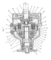
- Fig. 1 shows a drive unit in longitudinal section along the line I-I of Fig. 2nd
- Fig. 2 is a cross section along the line II-II of Fig. 1st
- the drive unit 1 shown consists of a drive shaft 2 and a Output shaft 3, which in a housing 4 by means of bearings 5, 6 to each other are mounted concentrically, a coupling device 7 and one Braking device 8.
- the drive shaft 2 is a not shown Power source driven and has at its end projecting into the housing 4 Bore 9 for receiving a pin 11 supported by a needle bearing 10 the output shaft 3.
- a flange 12 arranged for connection to a driven unit, not shown.
- the coupling device 7 is in the illustrated embodiment from a non-rotatably and axially displaceably mounted on the output shaft 3 Coupling part 13, an axially acting compression spring 14, one Multi-plate clutch 15 and one firmly connected to the drive shaft 2 Coupling part 16.
- the multi-plate clutch 15 has a number of between the pressing surfaces 17, 18 arranged slats 19, 20, the outer slats 19 in the Driver 21 of the coupling part 16 of the drive shaft 2 and the inner plates 20 engage in the driver 22 of the output shaft 3.
- the driver 22 is rotatably with the output shaft 3 connected and held axially by the nut 23.
- the Pressure surfaces 17 and 18 are through the end faces of the coupling part 13 or the disc 24 held on the carrier 22.
- the axially displaceable coupling part 13 carries one by means of a Ball bearing 25 axially immovable and rotatably mounted in the circumferential direction Ring 26.
- This ring 26 is on the coupling device 7 facing Side attached a disc 27 with scenes 28, the control surfaces through Sections of a screw plane surface are formed.
- the axis of the scenes 28 defining screw runs coaxially to the axis of the shafts 2 and 3 respectively
- the disk 27 is attached to the ring 26 by means of three pins 29.
- the spring-loaded coupling part 13 has three evenly Scope distributed openings 30 in which the releasers 31 are mounted.
- releasers 31 are designed as balls and the openings 30 as cylindrical bores in which the balls 31 are mounted.
- the releasers 31 are on the one hand on the surfaces of the scenes 28 and on the other hand on the disc 32 supported.
- the disc 32 is like the spring-loaded coupling part 13 and the Driver 22 by means of a toothed shaft connection 33 with the output shaft in a rotationally fixed manner connected.
- the washer 32 is axially secured with the retaining ring 34.
- the pins 29 used to fasten the disk 27 protrude into bores 35 of the spring-loaded coupling part 13, the diameter of which is larger than that of the pens.
- three are preferably on the circumference evenly distributed pins 29 provided. They act with the holes 35 together as a limit stop for the pivoting movement of the ring 26 compared to the spring-loaded coupling part 13.
- the braking device 8 consists of a brake band 36, the ends of which in Housing 4 are tensioned and can be operated by means of a cable 37.
- the output shaft 3 comes to a standstill when between the transferable Torque of the multi-plate clutch 15 and the sum of the output torque the output shaft 3 and that generated by the braking device 8 Braking torque an equilibrium state is reached.
- this device according to the invention is both for Steering devices on single-axle vehicles as well as for other drives in vehicle and mechanical engineering possible.
Landscapes
- Engineering & Computer Science (AREA)
- General Engineering & Computer Science (AREA)
- Mechanical Engineering (AREA)
- Braking Arrangements (AREA)
- Mechanical Operated Clutches (AREA)
- One-Way And Automatic Clutches, And Combinations Of Different Clutches (AREA)
Description
Claims (7)
- Kupplungs- und Bremseinrichtung für eine Antriebseinheit mit einer Antriebswelle und einer zu dieser konzentrisch gelagerten Abtriebswelle, wobei ein Kupplungsteil mit der einen der beiden Wellen fest verbunden ist und zumindest ein weiterer federbelasteter Kupplungsteil auf der anderen der beiden Wellen drehfest und axial verschiebbar angeordnet ist und die beiden Kupplungsteile über einen konzentrisch zu den Wellen gelagerten Ring mit mindestens zwei am Umfang verteilten Kulissen und je einem an den Kulissen angreifenden Ausrücker durch eine auf den Ring einwirkende Bremseinrichtung voneinander trennbar sind, dadurch gekennzeichnet, daß der Ring (26) auf dem federbelasteten Kupplungsteil (13) axial unverschiebbar und in Umfangsrichtung drehbar gelagert ist, und daß die an den Steuerflächen der Kulissen (28) des Ringes (26) angreifenden Ausrücker (31) an der Abtriebswelle (3) abgestützt sind.
- Kupplungs- und Bremseinrichtung nach Anspruch 1, dadurch gekennzeichnet, daß zur Abstützung der Ausrücker (31) an der Abtriebswelle (3) an dieser eine Scheibe (32) axial unverschiebbar festgelegt ist.
- Kupplungs- und Bremseinrichtung nach Anspruch 1 oder 2, dadurch gekennzeichnet, daß der federbelastete Kupplungsteil (13) mindestens zwei parallel zur Achse der Abtriebswelle (3) verlaufende Durchbrüche (30) zur Lagerung der Ausrücker (31) aufweist.
- Kupplungs- und Bremseinrichtung nach einem der Ansprüche 1 bis 3, dadurch gekennzeichnet, daß als Ausrücker (31) Kugeln, vorzugsweise Wälzlagerkugeln dienen.
- Kupplungs- und Bremseinrichtung nach einem oder mehreren der Ansprüche 1 bis 4, dadurch gekennzeichnet, daß die am Ring (26) angebrachten Steuerflächen der Kulissen (28) als Schraubenebenenflächen ausgeführt sind und daß die Achse der Schraube koaxial zu den der Wellen (2,3) liegt.
- Kupplungs- und Bremseinrichtung nach dem Anspruch 5 , dadurch gekennzeichnet, daß die die Kulissen (28) bildenden Schraubenebenenflächen auf einer Scheibe (27) angebracht sind, die mittels mehrerer Stifte (29) am Ring (26) der Kupplungseinrichtung (7) zugewendet befestigt ist, wobei der Ring (26) durch ein Kugellager (25) am federbelasteten Kupplungsteil (13) gelagert ist.
- Kupplungs- und Bremseinrichtung nach Anspruch 6, dadurch gekennzeichnet, daß die Stifte (29) in als Begrenzungsanschläge dienende, größeren Durchmesser als die Stifte (29) aufweisende Bohrungen (35) des federbelasteten Kupplungsteiles (13) eingreifen.
Applications Claiming Priority (3)
| Application Number | Priority Date | Filing Date | Title |
|---|---|---|---|
| AT136197 | 1997-08-13 | ||
| AT0136197A AT404978B (de) | 1997-08-13 | 1997-08-13 | Kupplungs- und bremseinrichtung für eine antriebseinheit |
| AT1361/97 | 1997-08-13 |
Publications (3)
| Publication Number | Publication Date |
|---|---|
| EP0897072A2 EP0897072A2 (de) | 1999-02-17 |
| EP0897072A3 EP0897072A3 (de) | 2001-11-28 |
| EP0897072B1 true EP0897072B1 (de) | 2003-05-21 |
Family
ID=3512229
Family Applications (1)
| Application Number | Title | Priority Date | Filing Date |
|---|---|---|---|
| EP98890232A Expired - Lifetime EP0897072B1 (de) | 1997-08-13 | 1998-08-06 | Kupplungs- und Bremseinrichtung für eine Antriebseinheit |
Country Status (5)
| Country | Link |
|---|---|
| EP (1) | EP0897072B1 (de) |
| AT (1) | AT404978B (de) |
| CZ (1) | CZ294218B6 (de) |
| DE (1) | DE59808418D1 (de) |
| SK (1) | SK284435B6 (de) |
Families Citing this family (1)
| Publication number | Priority date | Publication date | Assignee | Title |
|---|---|---|---|---|
| DE102013110430A1 (de) * | 2013-09-20 | 2015-03-26 | Wittenstein Ag | Bremsvorrichtung |
Family Cites Families (5)
| Publication number | Priority date | Publication date | Assignee | Title |
|---|---|---|---|---|
| FR1022363A (fr) * | 1949-07-22 | 1953-03-04 | Odero Terni Orlando Per La Cos | Direction à friction pour véhicules automobiles à roues ou à chenilles avec débrayage au moyen d'un frein servomoteur |
| FR1060318A (fr) * | 1951-10-25 | 1954-04-01 | Eisenwerk Weserhu Tte A G | Accouplement à friction à disques |
| US4597477A (en) * | 1984-04-16 | 1986-07-01 | Sundstrand Corporation | Bidirectional brake |
| US4693349A (en) * | 1986-07-25 | 1987-09-15 | Sundstrand Corporation | Torque limiting apparatus |
| AT397546B (de) | 1992-08-21 | 1994-04-25 | Bauer & Co Gmbh Reform Werke | Kupplungs- und bremseinrichtung |
-
1997
- 1997-08-13 AT AT0136197A patent/AT404978B/de not_active IP Right Cessation
-
1998
- 1998-08-06 DE DE59808418T patent/DE59808418D1/de not_active Expired - Lifetime
- 1998-08-06 EP EP98890232A patent/EP0897072B1/de not_active Expired - Lifetime
- 1998-08-13 CZ CZ19982570A patent/CZ294218B6/cs not_active IP Right Cessation
- 1998-08-13 SK SK1103-98A patent/SK284435B6/sk not_active IP Right Cessation
Also Published As
| Publication number | Publication date |
|---|---|
| CZ257098A3 (cs) | 1999-02-17 |
| EP0897072A2 (de) | 1999-02-17 |
| ATA136197A (de) | 1998-08-15 |
| AT404978B (de) | 1999-04-26 |
| SK110398A3 (en) | 1999-03-12 |
| EP0897072A3 (de) | 2001-11-28 |
| DE59808418D1 (de) | 2003-06-26 |
| CZ294218B6 (cs) | 2004-10-13 |
| SK284435B6 (sk) | 2005-04-01 |
Similar Documents
| Publication | Publication Date | Title |
|---|---|---|
| DE102020123833B4 (de) | Feststellbremsvorrichtung für ein Fahrzeug | |
| DE3631946C2 (de) | ||
| DE19922333A1 (de) | Scheibenbremse mit Feststellbremsfunktion | |
| EP0881072B1 (de) | Wischzylinderantrieb einer Stichtiefdruckmaschine | |
| DE2361019C2 (de) | Lösbare starre Kupplung | |
| DE3342880A1 (de) | Kupplung fuer elektrowerkzeuge | |
| EP0897072B1 (de) | Kupplungs- und Bremseinrichtung für eine Antriebseinheit | |
| DE3502341A1 (de) | Steuerung fuer eine kupplung | |
| DE3142799C2 (de) | Mechanisch betätigte Gleitsattel-Scheibenbremse | |
| DE102009039467A1 (de) | Doppelreibungskupplung für ein Fahrzeug | |
| DE3327984C2 (de) | ||
| AT397546B (de) | Kupplungs- und bremseinrichtung | |
| DE1505944B2 (de) | Überlast-Scheibenreibungskupplung | |
| WO2008043732A1 (de) | Kupplung mit planetengetriebe | |
| DE3109622A1 (de) | Servolenkvorrichtung fuer kraftfahrzeuge | |
| DE10314219A1 (de) | Überlastkupplung | |
| DE19512979A1 (de) | Antriebsaggregat mit einem Motor, einem Planetengetriebe und einem Abtriebselement | |
| DE19512976A1 (de) | Antriebsaggregat, insbesondere Drehwerksantrieb, mit einem Planetengetriebe und einem Abtriebselement | |
| DE3724232A1 (de) | Bohrstaender | |
| AT202412B (de) | Stufenlos regelbares Keilriemengetriebe | |
| DE4321670C1 (de) | Elektromotorische Servolenkung | |
| EP2004472B1 (de) | Verstellbare lenkspindelanordnung | |
| EP1673549B1 (de) | Scheibenbremse mit elektromotorisch angetriebener nachstellvorrichtung | |
| DE2843572A1 (de) | Vorrichtung zur uebertragung einer bewegung zwischen einer welle und einem drehelement | |
| DE3935034A1 (de) | Ueberlastkupplung, insbesondere zur verwendung bei kettenantrieben, wie vor allem hobelantrieben u. dgl. |
Legal Events
| Date | Code | Title | Description |
|---|---|---|---|
| PUAI | Public reference made under article 153(3) epc to a published international application that has entered the european phase |
Free format text: ORIGINAL CODE: 0009012 |
|
| AK | Designated contracting states |
Kind code of ref document: A2 Designated state(s): AT BE CH CY DE DK ES FI FR GB GR IE IT LI LU MC NL PT SE Kind code of ref document: A2 Designated state(s): CH DE IT LI |
|
| AX | Request for extension of the european patent |
Free format text: AL;LT;LV;MK;RO;SI |
|
| PUAL | Search report despatched |
Free format text: ORIGINAL CODE: 0009013 |
|
| AK | Designated contracting states |
Kind code of ref document: A3 Designated state(s): AT BE CH CY DE DK ES FI FR GB GR IE IT LI LU MC NL PT SE |
|
| AX | Request for extension of the european patent |
Free format text: AL;LT;LV;MK;RO;SI |
|
| RIC1 | Information provided on ipc code assigned before grant |
Free format text: 7F 16D 67/02 A, 7B 62D 11/08 B |
|
| 17P | Request for examination filed |
Effective date: 20020528 |
|
| AKX | Designation fees paid |
Free format text: AT BE CH CY DE DK ES FI FR GB GR IE IT LI LU MC NL PT SE |
|
| AXX | Extension fees paid |
Free format text: AL PAYMENT 20020528;LT PAYMENT 20020528;LV PAYMENT 20020528;MK PAYMENT 20020528;RO PAYMENT 20020528;SI PAYMENT 20020528 |
|
| GRAH | Despatch of communication of intention to grant a patent |
Free format text: ORIGINAL CODE: EPIDOS IGRA |
|
| RBV | Designated contracting states (corrected) |
Designated state(s): CH DE IT LI |
|
| GRAH | Despatch of communication of intention to grant a patent |
Free format text: ORIGINAL CODE: EPIDOS IGRA |
|
| GRAA | (expected) grant |
Free format text: ORIGINAL CODE: 0009210 |
|
| AK | Designated contracting states |
Designated state(s): CH DE IT LI |
|
| AX | Request for extension of the european patent |
Extension state: AL LT LV MK RO SI |
|
| REG | Reference to a national code |
Ref country code: CH Ref legal event code: EP |
|
| REG | Reference to a national code |
Ref country code: IE Ref legal event code: FG4D Free format text: GERMAN |
|
| REF | Corresponds to: |
Ref document number: 59808418 Country of ref document: DE Date of ref document: 20030626 Kind code of ref document: P |
|
| REG | Reference to a national code |
Ref country code: CH Ref legal event code: NV Representative=s name: MOINAS & SAVOYE SA |
|
| LTIE | Lt: invalidation of european patent or patent extension |
Effective date: 20030521 |
|
| REG | Reference to a national code |
Ref country code: IE Ref legal event code: FD4D Ref document number: 0897072E Country of ref document: IE |
|
| PLBE | No opposition filed within time limit |
Free format text: ORIGINAL CODE: 0009261 |
|
| STAA | Information on the status of an ep patent application or granted ep patent |
Free format text: STATUS: NO OPPOSITION FILED WITHIN TIME LIMIT |
|
| 26N | No opposition filed |
Effective date: 20040224 |
|
| PGFP | Annual fee paid to national office [announced via postgrant information from national office to epo] |
Ref country code: CH Payment date: 20100817 Year of fee payment: 13 |
|
| PGFP | Annual fee paid to national office [announced via postgrant information from national office to epo] |
Ref country code: IT Payment date: 20100827 Year of fee payment: 13 |
|
| PGFP | Annual fee paid to national office [announced via postgrant information from national office to epo] |
Ref country code: DE Payment date: 20100902 Year of fee payment: 13 |
|
| REG | Reference to a national code |
Ref country code: CH Ref legal event code: PL |
|
| PG25 | Lapsed in a contracting state [announced via postgrant information from national office to epo] |
Ref country code: LI Free format text: LAPSE BECAUSE OF NON-PAYMENT OF DUE FEES Effective date: 20110831 Ref country code: CH Free format text: LAPSE BECAUSE OF NON-PAYMENT OF DUE FEES Effective date: 20110831 |
|
| PG25 | Lapsed in a contracting state [announced via postgrant information from national office to epo] |
Ref country code: IT Free format text: LAPSE BECAUSE OF NON-PAYMENT OF DUE FEES Effective date: 20110806 |
|
| REG | Reference to a national code |
Ref country code: DE Ref legal event code: R119 Ref document number: 59808418 Country of ref document: DE Effective date: 20120301 |
|
| PG25 | Lapsed in a contracting state [announced via postgrant information from national office to epo] |
Ref country code: DE Free format text: LAPSE BECAUSE OF NON-PAYMENT OF DUE FEES Effective date: 20120301 |